LG 26LG3 Series User manual

LCD TV
OWNER’S MANUAL
LCD TV MODELS
26LG3***
32LG3***
37LG3***
42LG3***
47LG3***
Please read this manual carefully before operating your set.
Retain it for future reference.
Record model number and serial number of the set.
Refer to the label on the back cover and quote this
information.
To your dealer when requiring service.
ENGLISH
PP//NNOO MMFFLL4411441100111100 ((00880044--RREEVV0000))
PPrriinntteedd iinn KKoorreeaa


1
ACCESSORIES
Ensure that the following accessories are included with your TV If an accessory is missing, please contact the
dealer where you purchased the product
Owner's
Manual
Owner’s manual
Owner’s Manual Batteries
MUTE
PIP
AVMODE
FAV
TV
INPUT
STB
POWER
Q. MENU
MENU
OK
123
456
78
0
9
LIST
Q.VIEW
DVD
TIMESIZE
UPDA
TE
REVEAL
INDEX
HOLDTEXT
RETURN
P
Remote Control Power Cord
Polishing Cloth
Polishing cloth for use
on the screen
This feature is not
available
for all models
*Lightly wipe any stains or
fingerprints on the surface
of the TV with the polishing
cloth
Do not use excessive force
This may cause scratching or
discolouration
Bolts for stand assembly
(Refer to p.6)
( nly 26/32/37/42LG3***)
x 4 x 4
(Only 26/32/42LG3***)
Screw for stand fixing
(Refer to P 9)
ACCESSORIES
protection cover
or

PICTURE CONTROL
Watching PIP(Picture-in-Picture) .............................47
Picture Size (Aspect Ratio)Control.........................48
Preset Picture Settings
- Picture Mode-Preset............................................50
- Auto Colour Tone Control(Cool/Medium/Warm)
51
Manual Picture Adjustment
- Picture Mode-User ption................................52
- Colour Tone - User ption...............................53
-
Picture Improvement Technology
...................54
Advanced - Gamma......................................................55
Advanced - Film Mode ................................................56
Advanced - Black(Darkness) Level...........................57
Advanced - Eye Care...................................................58
Picture Reset..................................................................59
Power Indicator .............................................................60
Factory Reset .................................................................61
WATCHING TV /PROGRAMME CONTROL
Remote Control Key Functions..................................30
Turning on the TV....................................................... 32
Programme Selection ................................................. 32
Volume Adjustment......................................................32
Quick Menu................................................................... 33
n Screen Menus Selection and Adjustment ......34
PICTURE CONTROL
WATCHING TV / PROGRAMME CONTROL
AACCCCEESSSSRRIIEESS.....................................................1
2
CONTENTS
CONTENTS
PREPARATION
Front Panel Controls................................................... 4
Back Panel Information .............................................. 5
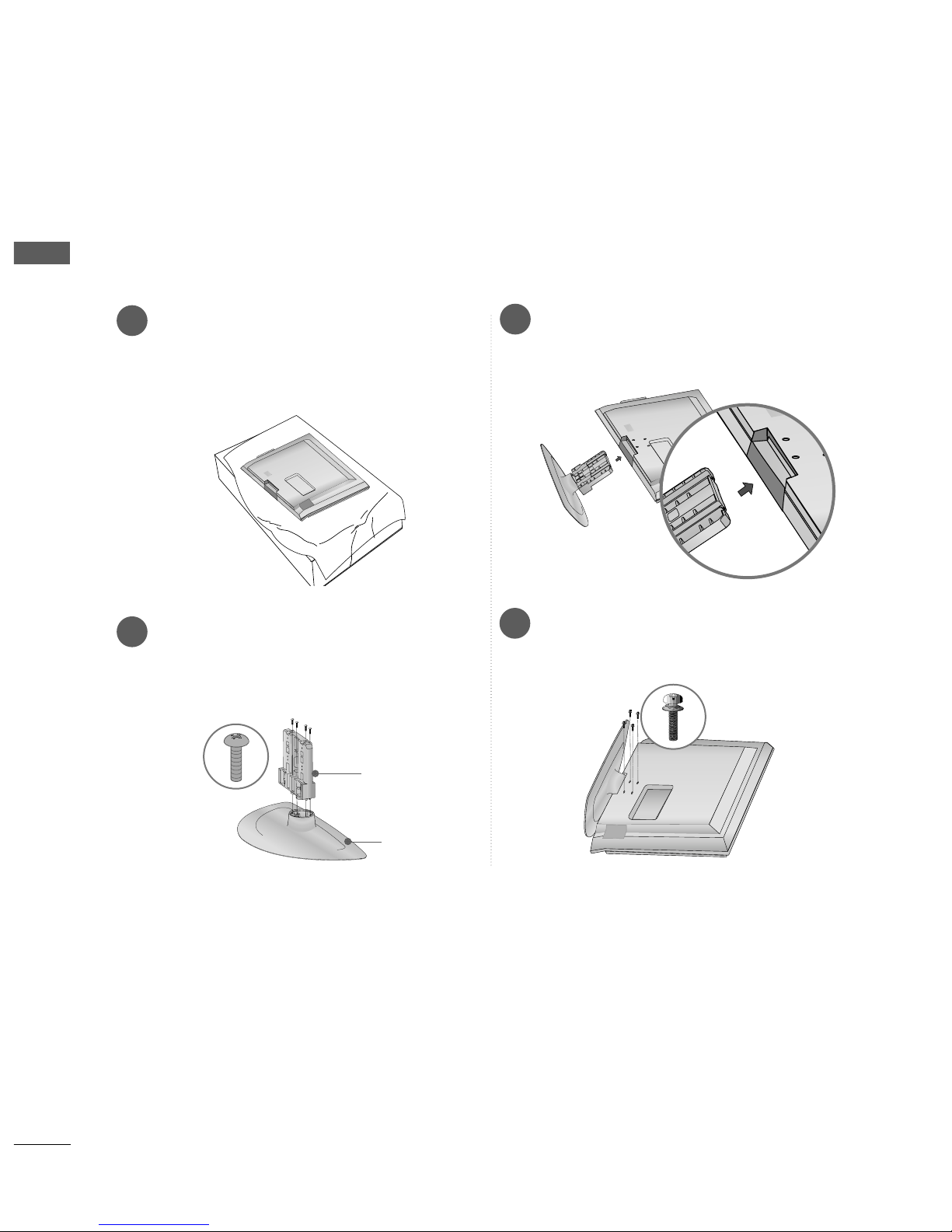
Stand Installation ........................................................ 6
Please set it up carefully so the product
does not fall over.
. . . . . . . . . . . . . . . . . . . . . . . . . .7
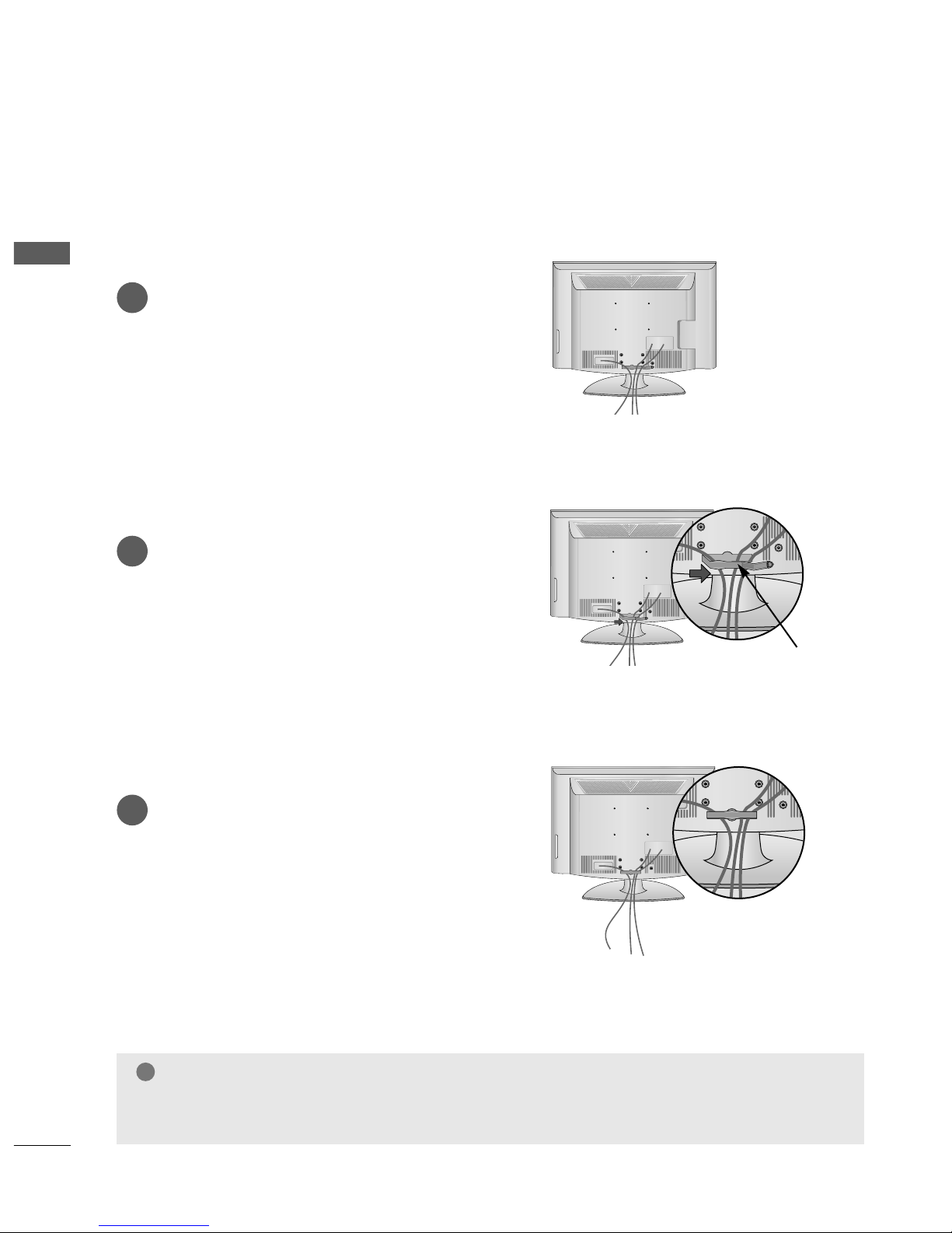
Back Cover for Wire Arrangement........................... 8
Swivel Stand ................................................................. 9
Desktop Pedestal Installation ................................. 10
Wall Mount: Horizontal installation....................... 11
Not using the desk-type stand................................11
Antenna Connection ................................................ 12
PREPARATION
EXTERNAL EQUIPMENT SETUP
HD Receiver Setup .......................................................13
DVD Setup..................................................................... 16
VCR Setup..................................................................... 19
ther A/V Source Setup .......................................... 22
PC Setup.........................................................................23
- Screen Setup for PC Mode................................26
Auto Programme Tuning............................................ 35
Manual Programme Tuning ....................................... 36
Fine Tuning .....................................................................37
Assigning a Station Name ..........................................38
Booster............................................................................39
Programme Edit ........................................................... 40
Favourite Programme .................................................. 41
Selecting the Programme List .................................. 42
.................................................................. 43
Key lock.......................................................................... 45
AV Mode.........................................................................46

SOUND & LANGUAGE CONTROL
Auto Volume Leveler ....................................................62
Preset Sound Settings - Sound Mode....................63
Sound Setting Adjustment - User Mode ...............64
Balance............................................................................65
TV Speakers n/ ff Setup .......................................66
I/II
- Stereo/Dual Reception ....................................... 67
- NICAM Reception ....................................................... 68
- Speaker Sound utput Selection.................... 68
n-Screen Menu Language Selection
...................... 69
3
CONTENTS
APPENDIX
Troubleshooting............................................................77
Maintenance .................................................................79
Product Specifications ................................................80
Programming the Remote Control ......................... 81
IR Codes ....................................................................... 83
External Control Through RS-232C ..................... 85
TIME SETTING
Clock Setup......................................................................70
Auto n/ ff Timer Setting .........................................71
Sleep Timer Setting........................................................72
Auto Shut-off Setting...................................................73
TELETEXT
Switch n/ ff ..............................................................74
SIMPLE Text....................................................................74
T P Text .........................................................................75
FASTEXT .........................................................................75
Special Teletext Functions..........................................76

4
FRONT PANEL CONTROLS
PREPARATION
PREPARATION
■
This is a simplified representation of the front panel. Image shown may differ from your TV.
■
If your product has a protection film attached, remove the film and then wipe the product with a polishing
cloth.
POWER
Remote Control Sensor
Power/Standby Indicator
• illuminates red in standby mode.
• illuminates blue when the TV is switched on.
Note: You can ad ust PPoowweerr IInnddiiccaattoorrin
the Option menu.
P
MENU
INPUT
OK
+
-
PRO RAMME
VOLUME
OK
MENU
INPUT

5
PREPARATION
1
HDMI INHDMI/DVI IN
1
1
2
2
RGB IN
COMPONENT IN
AUDIO
AV
VIDEO
VARIABLE
AUDIO OUT
S-Video Input
Connect S-Video out from
an S-VIDE device.
Audio/Video Input
Connect audio/video out-
put from an external
device to these jacks.
HDMI INHDMI INHDMI/DVI INHDMI/DVI IN
1
1
2
2
AUDIO
RGB
(PC)
RGB INRGB IN
COMPONENT INCOMPONENT IN
AUDIO
VIDEO
L(MONO)
R
AUDIOAUDIO
ANTENNA
IN
(RGB/DVI)
VIDEOVIDEO
RS-232C IN
(CONTROL)
-+
MONO(8 )MONO(8 )
AV IN 1
SPEAKER
OUT
3 4
2
7
5
Power Cord Socket
This TV operates on an AC power. The voltage is
indicated on the Specifications page. Never
attempt to operate the TV on DC power.
HDMI Input
Connect a HDMI signal to HDMI IN.
r DVI(VIDE )signal to HDMI/DVI port with DVI
to HDMI cable.
RGB/Audio Input
Connect the monitor output from a PC to the
appropriate input port.
RS-232C Input (CONTROL) Port
Connect the serial port of the control devices to
the RS-232C jack.
(This feature is not available for all models.)
Audio/Video Input (AV IN 1)
Connect audio/video output from an external
device to these jacks.
SPEAKER OUTPUT
Audio out for a external speaker system.
Component Input
Connect a component video/audio device to
these jacks.
Antenna Input
Connect RF antenna to this jack.
1
2
3
4
5
6
7
8
6
8
BACK PANEL INFORMATION
A
Image shown may differ from your TV.

6
PREPARATION
PREPARATION
13
4
Carefully place the TV screen side down on a
cushioned surface to protect the screen from
damage.
2Assemble the parts of the SSttaanndd BBooddyywith
the CCoovveerr BBaasseeof the TV.
Assemble the TV as shown.
Fix the 4 bolts securely using the holes in the
back of the TV.
Stand Body
Cover Base
STAND INSTALLATION
26/32/37/42LG3***
■
Image shown may differ from your TV
■
When assembling the desk type stand, check whether the bolt is fully tightened. (If not tightened fully, thep
roduct can tilt forward after the product installation.) If you tighten the bolt with excessive force, the boltcan
deviate from abrasion of the tightening part of the bolt.

7
PREPARATION
PLEASE SET IT UP CAREFULLY SO THE PRODUCT DOES NOT
FALL OVER
AYou should purchase necessary components to fix the TV to the wall on the market
APosition the TV close to the wall to avoid the possibility of it falling when pushed
AThe instructions shown below are a safer way to set up the TV, which is to fix it to the wall, avoiding the
possibility of it falling forwards if pulled This will prevent the TV from falling forward and causing injury
This will also prevent the TV from damage Ensure that children do not climb or hang from the TV
NOTE
!
G When moving the TV undo the cords first
G Use a platform or cabinet string and large enough to support the size and weight of the TV
G To use the TV safely make sure that the height of the bracket on the wall and on the TV is the same
3
1
2
Use the eye-bolts or TV brackets/bolts to fix the product to the wall as shown in the picture.
(If your TV has bolts in the eyebolts, loosen then bolts.)
* Insert the eye-bolts or TV brackets/bolts and tighten them securely in the upper holes.
Secure the wall brackets with bolts to the wall.
Ensure that both brackets are even.
3Use a strong cord to secure the TV.
Secure the cord in such a way that it becomes taught when the TV is in position.
2
1
2
1

8
PREPARATION
PREPARATION
BACK COVER FOR WIRE ARRANGEMENT
Connect the cables as necessary.
To connect additional equipment, see the
External Equipment Setup section of the
manual.
1
pen the CCAABBLLEE MMAANNAAGGEEMMEENNTT CCLLIIPPas
shown and manage the cables.
2
CABLE MANAGEMENT CLIP
Fit the CCAABBLLEE MMAANNAAGGEEMMEENNTT CCLLIIPPas
shown.
3
NOTE
!
GGDo not use the CABLE MANAGEMENT CLIP to lift the TV.
- If the TV is dropped, you may be injured or the TV may be damaged.

9
PREPARATION
SWIVEL STAND
This feature is not available for all models.
After installing the TV, you can adjust the TV manually
to the left or right direction by 20 degrees to suit your
viewing position.
Attaching the TV to a desk (Only 26/32/42LG3***)
The TV must be attached to desk so it cannot be pulled in a forward/backward direction, potentially causing
injury or damaging the product. Use only an attached screw.
1-Screw
(provided as parts of the product)
Desk
Stand
WARNING
!
GG To prevent TV from falling over, the TV should be securely attached to the floor/wall per installation
instructions Tipping, shaking, or rocking the machine may cause injury

10
■The TV can be installed in various ways such as on a wall, or on a desktop etc
■The TV is designed to be mounted horizontally
PREPARATION
PREPARATION
PREPARATION
DESKTOP PEDESTAL INSTALLATION
For adequate ventilation allow a clearance of 4” (10cm) all around the TV .
4 inches
4 inches
4 inches 4 inches
Power Supply
Circuit breaker
EARTHING
Ensure that you connect the earth wire to prevent possible electric shock. If grounding methods are not
possible, have a qualified electrician install a separate circuit breaker.
Do not try to earth the TV by connecting it to telephone wires, lightening rods or gas pipes.

11
PREPARATION
WALL MOUNT: HORIZONTAL INSTALLATION
For adequate ventilation allow a clearance of 4” (10cm) all around the TV. We recommend that you use a wall
mounting bracket of LG brand when mounting the TV to a wall.
4 inches
4 inches
4 inches
4 inches
4 inches
When installing the wall-mounted unit, use the protection cover for desk-type stand installation
NOT USING THE DESK-TYPE STAND
or

HDMI INHDMI/DVI IN
1
1
2
2
RGB IN
COMPONENT IN
AUDIO
ANTENNA
IN
AV
VIDEO
VARIABLE
AUDIO OUT
12
PREPARATION
PREPARATION
PREPARATION
ANTENNA CONNECTION
■For optimum picture quality, adjust antenna direction.
■An antenna cable and converter are not supplied.
■To prevent damage do not connect to the mains outlet until all connections are made between the devices
HDMI INHDMI/DVI IN
1
1
2
2
RGB IN
COMPONENT IN
AUDIO
ANTENNA
IN
AV
VIDEO
VARIABLE
AUDIO OUT
Multi-family Dwellings/Apartments
(Connect to wall antenna socket)
Single-family Dwellings /Houses
(Connect to wall jack for outdoor antenna)
Outdoor
Antenna
Wall
Antenna
Socket
RF Coaxial Wire (75 ohm)
Antenna
UHF
Signal
Amplifier
VHF
■In poor signal areas, to achieve better picture quality it may be necessary to install a signal amplifier to the
antenna as shown above.
■If signal needs to be split for two TVs,use an antenna signal splitter for connection.

13
EXTERNAL EQUIPMENT SETUP
■To avoid damaging any equipment, never plug in any power cords until you have finished connecting all equipment
■
Image shown may differ from your TV.
COMPONENT IN
AUDIO
VIDEO
MONO(8 )
HDMI INHDMI DVI IN
HDMI/DVI IN
1
COMPONENT IN
AUDIO
VIDEO
MONO(8 )
1
2
COMPONENT IN
AUDIO
VIDEO
HDMI INHDMI DVI IN
HDMI/DVI IN
1
HDMI INHDMI/DVI IN
1
1
2
2
RGB IN
COMPONENT IN
AUDIO
VIDEO
MONO(8 )
HDMI INHDMI/DVI IN
1
1
2
2
RGB IN
COMPONENT IN
AUDIO
VIDEO
MONO(8 )
1 2
HD RECEIVER SETUP
Connecting with a component cable
Connect the video outputs (Y, PB, PR)of the digital TV
top box to the CCMMPPNNEENNTT IINN VVIIDDEEjacks on the
TV.
Connect the audio output of the digital set-top box to
the CCMMPPNNEENNTT IINN AAUUDDIIjacks on the TV.
Turn on the digital set-top box.
(Refer to the owner’s manual for the digital set-top box.)
Select CCoommppoonneenntt11 input source using the IINNPPUUTT
button on the remote control.
If connected to CCMMPPNNEENNTT IINN22, select
CCoommppoonneenntt22 input source.
2
3
4
1
Signal
480i/576i
480p/576p
720p/1080i
1080p
Component
Yes
Yes
Yes
Yes
( nly 50Hz, 60Hz)
HDMI1/DVI, HDMI2
No
Yes
Yes
Yes
(24Hz, 30Hz, 50Hz, 60Hz)

14
EXTERNAL EQUIPMENT SETUP
COMCOMPONENT IN
VIDEO
L(MONO)
R
AUDIOAUDIO
VIDEOVIDEO
-+
MONO(8 )MONO(8 )
IN 1
AKER
UT
HDMI INHDMI DVI IN
HDMI/DVI INHDMI/DVI IN
1
COMPONENT IN
AUDIO
VIDEO
MONO(8 )
1
2
COMPONENT IN
HDMI INHDMI DVI IN
HDMI/DVI IN
1
HDMI INHDMI/DVI IN
1
1
2
2
RGB IN
COMPONENT IN
AUDIO
VIDEO
MONO(8 )
HDMI INHDMI/DVI IN
1
1
2
2
RGB IN
COMPONENT IN
AUDIO
VIDEO
MONO(8 )
1
Connecting a set-top box with a HDMI cable
Connect the HDMI output of the digital set-top box to
the HHDDMMII//DDVVII IINN 11 or HHDDMMII IINN 22 jack on the TV.
Select HHDDMMII11//DDVVII or HHDDMMII22input source using the
IINNPPUUTTbutton on the remote control.
Turn on the digital set-top box.
(Refer to the owner’s manual for the digital set-top box.)
2
3
1
GGTV can receive the video and audio signal simultaneously with using a HDMI cable.
GGIf the digital set-top box supports Auto HDMI function, the output resolution of the source device will
be automatically TV to 1280x720p.
GGIf the digital set-top box player does not support Auto HDMI, you need to TV the output resolution
appropriately.
To get the best picture quality, adjust the output resolution of the source device to 1280x720p.
NOTE
!

15
EXTERNAL EQUIPMENT SETUP
COMPONENT IN
AUDIO
VIDEO
MONO(8 )
HDMI INHDMI DVI IN
HDMI/DVI IN
1
1
2
COMPONENT INCOMPONENT IN
AUDIO
VIDEO
L(MONO)
R
AUDIOAUDIO
VIDEOVIDEO
-
+
MONO(8 )MONO(8 )
AV IN 1
SPEAKER
OUT
1
2
COMPONENT IN
HDMI INHDMI DVI IN
HDMI/DVI INHDMI/DVI IN
1
RGB
(PC)
RGB IN
RS-232C IN
(CONTROL)
HDMI INHDMI/DVI IN
1
1
2
2
RGB IN
COMPONENT IN
AUDIO
VIDEO
MONO(8 )
HDMI INHDMI/DVI IN
1
1
2
2
RGB IN
COMPONENT IN
AUDIO
VIDEO
MONO(8 )
AUDIO
(RGB/DVI)
12
Connect the DVI output of the digital set-top box to the HHDDMMII//DDVVII IINN 11 jack on the TV.
Connect the audio output of the digital set-top box to the AAUUDDII((RRGGBB//DDVVII)) jack on the TV.
Turn on the digital set-top box. (Refer to the owner’s manual for the digital set-top box.)
Select HHDDMMII11//DDVVII input source using the IINNPPUUTTbutton on the remote control.
2
3
4
1
Connecting with a HDMI to DVI cable
GGHDMI2 source does not support DVI source.
GG If the Set-Top Box has a DVI output and no HDMI output, a separated audio connection is necessary.
GGIf the Set-Top Box does not support Auto DVI, you need to set the output resolution appropriately.
NOTE
!

16
EXTERNAL EQUIPMENT SETUP
COMPONENT IN
AUDIO
VIDEO
MONO(8 )
HDMI INHDMI DVI IN
HDMI/DVI IN
1
1
2
COMPONENT IN
AUDIO
VIDEO
HDMI INHDMI DVI IN
AV IN 2
L/MONO
R
AUDIO
VIDEO
VARIABLE AUDIO OUT
1 2
DVD SETUP
Connecting with a component cable
Component Input ports
To achieve better picture quality, connect a DVD player to the component input ports as shown below
Component ports on the TV
YPBPR
Video output ports
on DVD player
Y
Y
Y
Y
PB
B-Y
Cb
Pb
PR
R-Y
Cr
Pr
Connect the video outputs (Y, PB, PR)of the DVD to the
CCMMPPNNEENNTT IINN VVIIDDEEjacks on the TV.
Connect the audio outputs of the DVD to the
CCMMPPNNEENNTT IINN AAUUDDIIjacks on the TV.
Turn on the DVD player, insert a DVD.
Select CCoommppoonneenntt11 input source using the IINNPPUUTTbutton
on the remote control.
If connected to CCMMPPNNEENNTT IINN22, select
CCoommppoonneenntt 22 input source.
Refer to the DVD player's manual for operating instructions.
2
3
4
5
1

17
EXTERNAL EQUIPMENT SETUP
Connecting with a S-Video cable
Connect the S-VIDE output of the DVD to the
SS--VVIIDDEEinput on the TV.
Connect the audio outputs of the DVD to the AAUUDDII
input jacks on the TV.
Turn on the DVD player, insert a DVD.
Select AAVV22input source using the IINNPPUUTTbutton on
the remote control.
Refer to the DVD player's manual for operating
instructions.
2
3
4
5
1
AV IN 2
L R
S-VIDEOVIDEO
OUTPUT
SWITCH
ANT IN
ANT OUT
12

18
EXTERNAL EQUIPMENT SETUP
COMPCOMPONENT IN
VIDEO
L(MONO)
R
AUDIOAUDIO
VIDEOVIDEO
-+
MONO(8 )MONO(8 )
1
ER
HDMI INHDMI DVI IN
HDMI/DVI INHDMI/DVI IN
1
1
2
COMPONENT IN
HDMI INHDMI DVI IN
AV IN 2
L/MONO
R
AUDIO
VIDEO
VARIABLE AUDIO OUT
1
Connecting with a HDMI cable
Connect the HDMI output of the DVD to the
HHDDMMII//DDVVII IINN 11 or HHDDMMII IINN 22jack on the TV.
Select HHDDMMII11//DDVVII or HHDDMMII22input source using the
IINNPPUUTTbutton on the remote control.
Refer to the DVD player's manual for operating instruc-
tions.
1
GGThe TV can receive video and audio signals simultaneously
when using a HDMI cable.
GG
If the DVD player supports Auto HDMI function, the output reso-
lution of the source device will be automatically TV to 1280x720p.
GGIf the DVD player does not support Auto HDMI, you must TV
the output resolution appropriately.
To get the best picture quality, adjust the output resolution of
the source device to 1280x720p.
NOTE
!
2
3
Other manuals for 26LG3 Series
2
This manual suits for next models
9
Table of contents
Other LG LCD TV manuals

LG
LG 47LF7700-ZC User manual

LG
LG 65UF860T Parts list manual

LG
LG 22LH2020 User manual

LG
LG EzSign 32LD452B User manual

LG
LG 26LH210C - 26In Lcd Tv Hdtv 1366X768 720P 12K:1 16:9 Blk 5Ms Hdmi Spkrs... User manual

LG
LG 19LG31 Series User manual

LG
LG 42LF5809 User manual

LG
LG 32LH1DC1 - - 32" LCD TV Installation guide

LG
LG 32LB3RS User manual

LG
LG 55LHX - - 54.6" LCD TV User manual