LG 32LG53 Series User manual

Please read this manual carefully before operating
your TV. Retain it for future reference.
Record model number and serial number of the TV.
Refer to the label on the back cover and quote this
information.
To your dealer when requiring service.
LCD TV
OWNER’S MANUAL
LCD TV MODELS
32LG53
37LG53
42LG53


GB-2
CONTENTS
PREPARATION
Accessories-------------------------------3
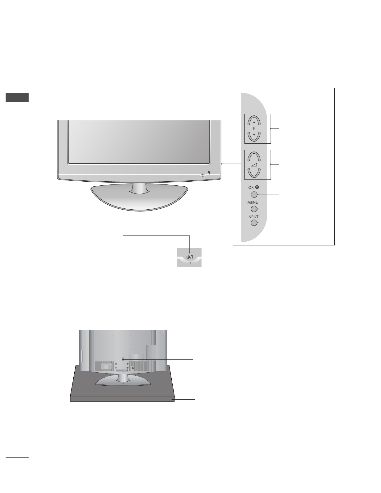
FrontPanelControls ------------------------4
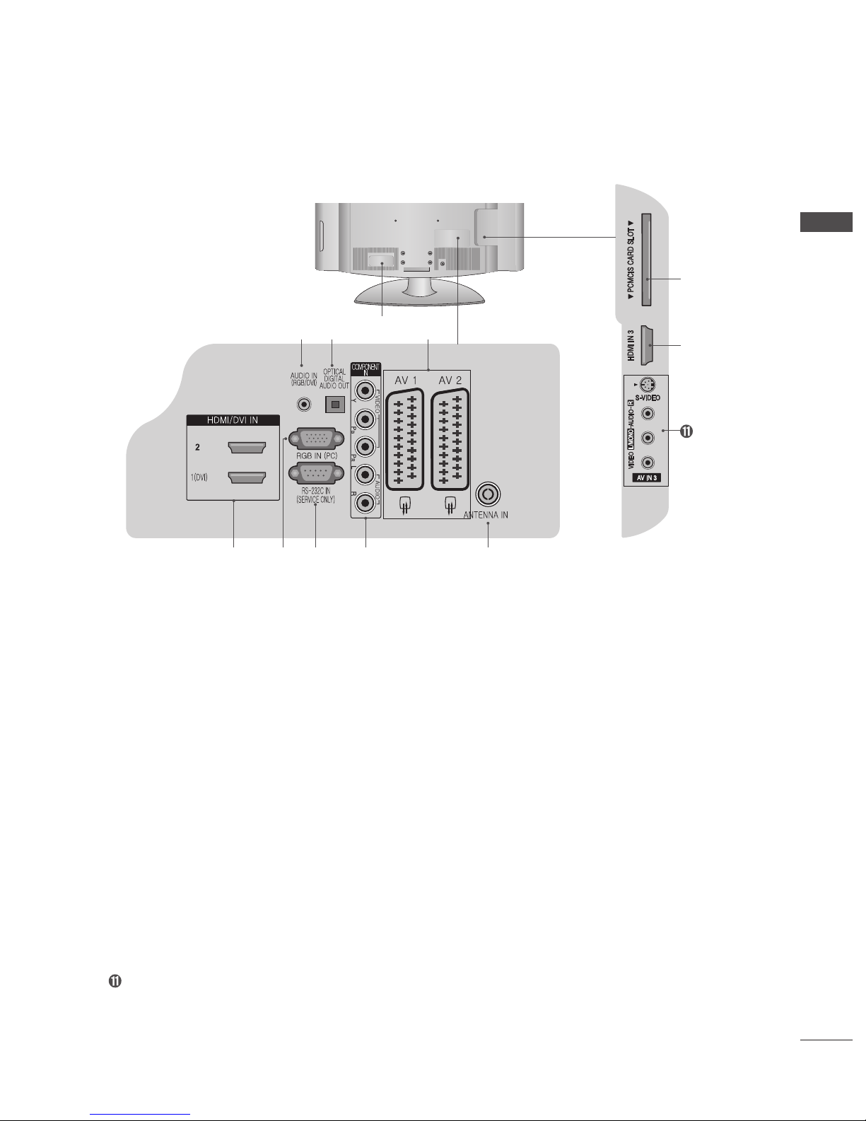
Back Panel Information- - - - - - - - - - - - - - - - - - - - - - - 5
StandInstallation---------------------------6
Please set it up carefully so the product
doesnotfallover.---------------------------7
Back Cover for Wire Arrangement - - - - - - - - - - - - - - - 8
Desktop Pedestal Installation - - - - - - - - - - - - - - - - - - 9
Wall Mount: Horizontal Installation - - - - - - - - - - - - - - - 9
Antenna or Cable Connection - - - - - - - - - - - - - - - - - 10
EXTERNAL EQUIPMENT SETUP
HDReceiverSetup ------------------------11
Digital Audio Out Setup - - - - - - - - - - - - - - - - - - - - - 12
DVDSetup ------------------------------13
VCRSetup ------------------------------15
Other A/V Source Setup - - - - - - - - - - - - - - - - - - - - - 17
InsertionofCIModule ----------------------17
PCSetup -------------------------------17
WATCHING TV/BASIC OPERATIONS
Remote Control key Functions - - - - - - - - - - - - - - - - 21
TurningontheTV -------------------------22
InstallationWizard-------------------------22
SwitchingChannel-------------------------23
VolumeControl ---------------------------23
Displaying Information - - - - - - - - - - - - - - - - - - - - - - 24
Displaying Channel List - - - - - - - - - - - - - - - - - - - - - 26
I/II-------------------------------------27
Setting the Subtitle (In Digital Mode Only) - - - - - - - - 28
Selecting the Main Input Source - - - - - - - - - - - - - - - 28
Selecting the Menu Language- - - - - - - - - - - - - - - - - 29
On-Screen Menus Selection and Adjustment - - - - - - 29
Setting the Aspect Ratio - - - - - - - - - - - - - - - - - - - - 31
Displaying Teletext Information - - - - - - - - - - - - - - - - 32
EPG (Electronic Programme Guide)
Viewing the Electronic Programme Guide- - - - - - - - - 33
FindingaProgramme-----------------------35
Viewing the Reserved Programme- - - - - - - - - - - - - - 36
CHANNEL SETUP
Setting Digital Channels - - - - - - - - - - - - - - - - - - - - - 37
Setting Analog Channels - - - - - - - - - - - - - - - - - - - - 43
PICTURE SETTINGS
Selecting a Picture Mode - - - - - - - - - - - - - - - - - - - - 46
Customizing the Picture Setting- - - - - - - - - - - - - - - - 46
NoiseReduction --------------------------47
Fleshtone -------------------------------47
SOUND SETTINGS
Setting the Sound Effect - - - - - - - - - - - - - - - - - - - - - 48
Adjusting the Sound Balance - - - - - - - - - - - - - - - - - 48
Adjusting the Volume Automatically - - - - - - - - - - - - - 49
Setting the TruSurround XT- - - - - - - - - - - - - - - - - - - 49
FEATURE SETTINGS
Setting the Time Information - - - - - - - - - - - - - - - - - - 50
Adjusting OSD Transparency - - - - - - - - - - - - - - - - - 50
Setting the PC (In PC Mode Only) - - - - - - - - - - - - - - 51
Setting the Screen (In Component or HDMI Mode Only)
52
DefaultSetting----------------------------52
DTV SETUP
ParentalControl---------------------------53
LanguageSetting--------------------------55
Schedule--------------------------------56
Miscellaneous Settings- - - - - - - - - - - - - - - - - - - - - - 57
SoftwareUpdate --------------------------58
System - - - - - - - - - - - - - - - - - - - - - - - - - - - - - - - - - 61
APPENDIX
MenuMap-------------------------------62
Troubleshooting---------------------------63
Maintenance-----------------------------64
Product Specications ----------------------64

GB-3
PREPERATION
PREPARATION
Accessories
Ensure that the following accessories are included with your TV. If an accessory is missing, please contact the dealer
where you purchased the TV.
/WNERgS
-ANUAL
Owner's manual
Owner’s Manual Batteries Remote Control
or
(only 32LG53**)
Power Cord Protection Cover Bolts for stand assembly
(Refer to p.6)
1-screw for stand xing
(Refer to p.4)
(Only 32/42LG53**)
Not using the desk-type stand
When installing the wall-mounted unit, use the protection cover
for desk-type stand installation.
Polishing Cloth
Polishing cloth for use on the screen.
Lightly wipe any stains or ngerprints on the
surface of the TV with the polishing cloth.
Do not use excessive force. This may
cause scratching or discolouration.
x 4 x 4 x 1

GB-4
PREPERATION
Front Panel Controls
■ Image shown may differ from your TV.
■ If your TV has a protection film attached, remove the film and then wipe the TV with a polishing cloth.
Attaching the TV to a desk (Only 32/42LG53**)
The TV must be attached to desk so it cannot be pulled in a forward/backward direction, potentially causing injury or
damaging the product. Use only an attached screw.
WARNING
To prevent TV from falling over, the TV should be securely attached to the floor/wall per installation instructions.
Tipping, shaking, or rocking the machine may cause injury.
►
1-screw
Desk
Intelligent sensor
Adjusts picture according to the surrounding conditions.
02
6/,
-%.5
).054
/+
02
6/,
-%.5
).054
/+
02
6/,
-%.5
).054
/+
02
6/,
-%.5
).054
/+
PROGRAMME
VOLUME
OK
MENU
INPUT
Power/Standby Indicator
• illuminates red in standby mode.
• illuminates blue when the TV is switched on.
Remote Control Sensor
POWER
02
6/,
-%.5
).054
/+
02
6/,
-%.5
).054
/+

GB-5
PREPERATION
Back Panel Information
■ Image shown may differ from your TV.
➊Power Cord Socket
This TV operates on an AC power. The voltage is indicated on the Specications page. Never attempt to operate the TV on DC
power.
➋AUDIO IN (RGB/DVI)
Connect the audio from a PC or DTV.
➌OPTICAL DIGITAL AUDIO OUT (In Digital Mode only)
Connect digital audio from various types of equipment.
Note: In standby mode, these ports do not work.
➍Euro Scart Socket (AV1/AV2)
Connect scart socket input or output from an external device to these jacks.
➎HDMI IN 1/2/3
Connect a HDMI signal to HDMI IN.
Or DVI (VIDEO) signal to HDMI/DVI port with DVI to HDMI cable. (HDMI1 only)
➏RGB IN (PC)
Connect the output from a PC.
➐RS-232C IN (SERVICE ONLY) PORT
Connect to the RS-232C port on a PC.
➑COMPONENT IN
Connect a component video/audio device to these jacks.
➒ANTENNA IN
Connect RF antenna to this jack.
➓PCMCIA (Personal Computer Memory Card International Association) CARD SLOT
AV (Audio/Video) IN 3
Connect audio/video output from an external device to these jacks.
S-VIDEO
Connect S-Video out from an S-VIDEO device.
02
6/,
-%.5
).054
/+
02
6/,
-%.5
).054
/+
➋➊
➌ ➍
➎ ➏ ➐ ➑ ➒
➓
➎

GB-6
PREPERATION
Stand Installation
When assembling the desk type stand, check whether the bolt is fully tightened. (If not tightened fully, the product can tilt
forward after the product installation.) If you tighten the bolt with excessive force, the bolt can deviate from abrasion of the
tightening part of the bolt.
➊Carefully place the TV screen side down on a
cushioned surface to protect the screen from damage. ➌Assemble the TV as shown.
➋Assemble the parts of the Stand Body with the Cover
Base of the TV. ➍Fix the 4 bolts securely using the holes in the back of
the TV.
Swivel Stand
After installing the TV, you can adjust the TV manually to the left
or right direction by 20 degrees to suit your viewing position.
Standby Body
Cover Base

GB-7
PREPERATION
Please set it up carefully so the product does not fall over.
■ You should purchase necessary components to fix the TV to the wall on the market.
■ Position the TV close to the wall to avoid the possibility of it falling when pushed.
■ The instructions shown below are a safer way to set up the TV, which is to fix it to the wall, avoiding the possibility of
it falling forwards if pulled. This will prevent the TV from falling forward and causing injury. This will also prevent the
TV from damage. Ensure that children do not climb or hang from the TV.
➊ Use the eye-bolts or TV brackets/bolts to fix the TV to the wall as shown in the picture.
(If your TV has bolts in the eyebolts, loosen these bolts.)
* Insert the eye-bolts or TV brackets/bolts and tighten them securely in the upper holes.
➋ Secure the wall brackets with the bolts on the wall. Match the height of the bracket that is mounted on the wall.
➌ Use a sturdy rope to tie the TV. It is safer to tie the rope so it becomes horizontal between the wall and the TV.
NOTE
When moving the TV undo the cords first.
Use a platform or cabinet strong and large enough to support the size and weight of the TV.
To use the TV safely make sure that the height of the bracket on the wall and on the TV is the same.
►
►
►
1
2
1
2
3

GB-8
PREPERATION
Back Cover for Wire Arrangement
➊ Connect the cables as necessary.
To connect additional equipment, see the External Equipment
Setup section of the manual.
➋ Open the CABLE MANAGEMENT CLIP as shown and manage
the cables.
➌ Fit the CABLE MANAGEMENT CLIP as shown.
NOTE
Do not use the CABLE MANAGEMENT CLIP to lift the TV.
If the TV is dropped, you may be injured or the TV may be damaged.
►
CABLE MANAGEMENT CLIP

GB-9
PREPERATION
Desktop Pedestal Installation
For adequate ventilation allow a clearance of 4” (10cm) all around the TV.
Wall Mount: Horizontal Installation
For adequate ventilation allow a clearance of 4” (10cm) all around the TV. We recommend that you use a wall mounting
bracket of LG brand when mounting the TV to a wall.
P R
VO L
O K
M E N U
IN P U T
/I
4 inches
4 inches4 inches 4 inches
4 inches
4 inches 4 inches
4 inches

GB-10
PREPERATION
Antenna or Cable Connection
To avoid damaging any equipment, never plug in any power cords until you have finished connecting all equipment.
Antenna (Analog TV or Digital TV)
Wall Antenna Socket or Outdoor Antenna without a Cable Box Connections.
For optimum picture quality, adjust antenna direction if needed.
Cable (Digital TV-C)
Using both cable and antenna
NOTE
If you connect both cable and antenna using diplexer to the TV, some channels with same frequency range may be
not tuned.
■ In poor signal areas, to achieve better picture quality it may be necessary to install a signal amplifier to the
antenna as shown above.
■ If signal needs to be split for two TVs, use an antenna signal splitter for connection.
►
2'").
0#
/04)#!,
$)')4!,
!5$)//54
!6 !6
!.4%..!).
23#).
#/.42/,3%26)#%
!5$)/).
2'"$6)
($-)$6)).
$6)
#/-0/.%.4
).
6)$%/ !5$)/
!.4%..!).
!6).
(0
, -/./
2
!5$)/
($-)). 0#-#)3#!2$3,/4
6)$%/
36)$%/
!#).
!6).
, -/./
2
!5$)/
6)$%/
36)$%/
($-)).
6!2)!",%
!5$)//54
!5$)/2'"
0#
2'").
#/-0/.%.4).
!5$)/
6)$%/
!6 !6
!.4%..!
).
Wall
Antenna
Socket
Outdoor
Antenna
(VHF, UHF)
Multi-family Dwellings/Apartments
(Connect to wall antenna socket)
RF Coaxial Wire (75 ohm)
Single-family Dwellings /Houses
(Connect to wall jack for outdoor antenna)
Take care not to bend the bronze wire when
connecting to an antenna port.
RF Coaxial Wire (75 ohm)
Cable TV
Wall Jack
2'").
0#
/04)#!,
$)')4!,
!5$)//54
!6 !6
!.4%..!).
23#).
#/.42/,3%26)#%
!5$)/).
2'"$6)
($-)$6)).
$6)
#/-0/.%.4
).
6)$%/ !5$)/
!.4%..!).
!6).
(0
, -/./
2
!5$)/
($-)). 0#-#)3#!2$3,/4
6)$%/
36)$%/
RF Coaxial Wire (75 ohm)
Antenna
2'").
0#
/04)#!,
$)')4!,
!5$)//54
!6 !6
!.4%..!).
23#).
#/.42/,3%26)#%
!5$)/).
2'"$6)
($-)$6)).
$6)
#/-0/.%.4
).
6)$%/ !5$)/
!.4%..!).
!6).
(0
, -/./
2
!5$)/
($-)). 0#-#)3#!2$3,/4
6)$%/
36)$%/
RF Coaxial Wire (75 ohm)
Cable TV
Wall Jack
Diplexer
(Signal
Combinner)

GB-11
EXTERNAL EQUIPMENT SETUP
■ Toavoiddamaginganyequipment,neverpluginanypowercordsuntilyouhavefinishedconnectingallequipment.
HD Receiver Setup
Connecting with a component cable
➊ Connectthevideooutputs(Y,PB,PR)ofthedigitalsettopboxtothe
COMPONENT IN VIDEOjacksontheTV.
➋Connecttheaudiooutputsofthedigitalset-topboxtotheCOMPONENT IN
AUDIOjacksontheTV.
➌Turnonthedigitalset-topbox.(Refertotheowner’smanualforthedigital
set-topbox.)
➍SelectComponentinputsourceusingtheINPUTbuttonontheremote
control.
NOTE
Dependingonthemanufacturer,theY,PB,PRjacksmaybeidentifiedas
Y/Pb/Pr,Y/B-Y/R-YorY/Cb/Cr.
Connecting with an HDMI cable
➊ ConnecttheHDMIoutputofthedigitalset-topboxtothe HDMI/DVI IN
1(DVI), HDMI/DVI IN 2 or HDMI IN3 jackontheTV.
➋Turnonthedigitalset-topbox.(Refertotheowner’smanualforthedigital
set-topbox.)
➌SelectHDMI1,HDMI2,orHDMI3inputsourceusingtheINPUTbuttononthe
remotecontrol.
►
2'"/54054
($-)$6)).
9
0
"
0
2
, 2
6)$%/
#/-0/.%.4).
!5$)/
!5$)/).
2'"$6)
2'"0#).
TV
STB
2'"/54054
($-)$6)).
9
0
"
0
2
, 2
6)$%/
#/-0/.%.4).
!5$)/
!5$)/).
2'"$6)
2'"0#).
TV
STB

GB-12
EXTERNAL EQUIPMENT SETUP
Connecting with a HDMI to DVI cable
➊ Connectthedigitalset-topboxtoHDMI/DVI IN 1(DVI)jackontheTV.
➋Connecttheaudiooutputofthedigitalset-topboxtotheAUDIO IN (RGB/
DVI)jackontheTV.
➌Turnonthedigitalset-topbox.(Refertotheowner’smanualforthedigital
set-topbox.)
➍SelectHDMI 1inputsourceusingtheINPUTbuttonontheremotecontrol.
Digital Audio Out Setup
(In Digital Mode Only)
■ SendingtheTV’sdigitalaudiosignaltoexternalaudioequipmentviathe
DigitalAudioOutput(Optical)port.
➊ ConnectoneendofanopticalcabletotheOPTICAL DIGITAL AUDIO OUT
jackontheTV.
➋Connecttheotherendoftheopticalcabletothedigitalaudio(optical)input
ontheaudioequipment.
➌Turnontheaudioequipment.(Refertotheexternalaudioequipment
instructionmanualforoperation.)
NOTE:
ThisfunctionisonlyavailableinDigitalTVorDigitalTV-Cmode.
CAUTION
Donotlookintotheopticaloutputport.Lookingatthelaserbeammay
damageyourvision.
►
►
RGB OUTPUT AUDIO
DVI-PC OUTPUT AUDIO
HDMI/DVI IN
AUDIO IN�
(RGB/DVI)
AUDIO IN�
(RGB/DVI)
RGB (PC) IN
TV
STB
RGB IN
(PC)
OPTICAL
DIGITAL
AUDIO OUT
AV 1 AV 2
ANTENNA IN
RS-232C IN
(CONTROL & SERVICE)
AUDIO IN
(RGB/DVI)
HDMI/DVI IN
2
1(DVI)
COMPONENT
IN
VIDEO AUDIO
TV

GB-13
EXTERNAL EQUIPMENT SETUP
DVD Setup
Connecting with a component cable
➊ Connectthevideooutputs(Y,PB,PR)oftheDVDtotheCOMPONENT IN
VIDEOjacksontheTV.
➋ConnecttheaudiooutputsoftheDVDtotheCOMPONENT IN AUDIOjackson
theTV.
➌TurnontheDVDplayer,insertaDVD.(RefertotheDVDplayer’smanualfor
operatinginstructions.)
➍SelectComponentinputsourceusingtheINPUTbuttonontheremotecontrol.
NOTE
Dependingonthemanufacturer,theY,PB,PRjacksmaybeidentifiedasY/Pb/Pr,
Y/B-Y/R-YorY/Cb/Cr.
Connecting with a Euro Scart cable
➊ConnecttheEuroscartsocketoftheDVDtotheAV1orAV2socketontheTV.
➋TurnontheDVDplayer,insertaDVD.(RefertotheDVDplayer’smanualfor
operatinginstructions.)
➌SelectAV1orAV2inputsourceusingtheINPUTbuttonontheremotecontrol.
IfconnectedtoAV2Euroscartsocket,selectAV2inputsource.
NOTE
AnyEuroscartcableusedmustbesignalshielded.
►
►
2!5$)/,
!5$)/
6)$%/
($-)$6)).
!6 !6
9
0
"
0
2
, 2
6)$%/
#/-0/.%.4).
!5$)/
TV
DVD
2!5$)/,
!5$)/
6)$%/
($-)$6)).
!6 !6
9
0
"
0
2
, 2
6)$%/
#/-0/.%.4).
!5$)/
TV
DVD

GB-14
EXTERNAL EQUIPMENT SETUP
Connecting with a S-Video cable
➊ ConnecttheS-VIDEOoutputoftheDVDtotheS-VIDEOinputjack
ontheTV.
➋ConnecttheaudiooutputsoftheDVDtotheAUDIOinputjacksonthe
TV.
➌TurnontheDVDplayer,insertaDVD.(RefertotheDVDplayer’s
manualforoperatinginstructions.)
➍SelectAV3(S-Video)inputsourceusingtheINPUTbuttononthe
remotecontrol.
Connecting with an HDMI cable
➊ConnecttheHDMIoutputoftheDVDtotheHDMI/DVI IN 1(DVI), HDMI/
DVI IN 2orHDMI IN 3jackontheTV.
➋TurnontheDVDplayer,insertaDVD.(RefertotheDVDplayer’smanual
foroperatinginstructions.)
➌SelectHDMI1,HDMI2orHDMI3inputsourceusingtheINPUTbuttonon
theremotecontrol.
NOTE
TheTVcanreceivevideoandaudiosignalssimultaneouslywhenusinga
HDMIcable.
IftheDVDdoesnotsupportAutoHDMI,youmustsettheoutputresolution
appropriately.Togetthebestpicturequality,adjusttheoutputresolutionof
thesourcedeviceto1280x720p.
►
►
RGB IN
(PC)
OPTICAL
DIGITAL
AUDIO OUT
AV 1 AV 2
ANTENNA IN
RS-232C IN
(CONTROL & SERVICE)
AUDIO IN
(RGB/DVI)
HDMI/DVI IN
2
1(DVI)
COMPONENT
IN
VIDEO AUDIO
RGB IN
(PC)
OPTICAL
DIGITAL
AUDIO OUT
AV 1 AV 2
ANTENNA IN
RS-232C IN
(CONTROL & SERVICE)
AUDIO IN
(RGB/DVI)
HDMI/DVI IN
2
1(DVI)
COMPONENT
IN
VIDEO AUDIO
RGB IN
(PC)
OPTICAL
DIGITAL
AUDIO OUT
AV 1 AV 2
ANTENNA IN
RS-232C IN
(CONTROL & SERVICE)
AUDIO IN
(RGB/DVI)
HDMI/DVI IN
2
1(DVI)
COMPONENT
IN
VIDEO AUDIO
AV IN 3
L/ MONO
R
AUDIO HDMI IN 3 PCMCIA CARD SLOT
VIDEO
S-VIDEO
(R) AUDIO (L)
AUDIO/
VIDEO
L R
S-VIDEOVIDEO
OUTPUT
SWITCH
ANT IN
ANT OUT
TV
DVD
2!5$)/,
!5$)/
6)$%/
($-)$6)).
!6 !6
9
0
"
0
2
, 2
6)$%/
#/-0/.%.4).
!5$)/
TV
DVD

GB-15
EXTERNAL EQUIPMENT SETUP
VCR Setup
■ Toavoidpicturenoise(interference),allowadequatedistancebetweentheVCRandTV.
■ If4:3pictureformatisusedforanextendedperiodthefixedimagesonthesidesofthescreenmayremainvisible.
Connecting with a RF Cable
➊ ConnecttheANTOUTsocketoftheVCRtotheANTENNA INsocketontheTV.
➋ConnecttheantennacabletotheANTINsocketoftheVCR.
➌PressthePLAYbuttonontheVCRandmatchtheappropriatechannelbetweentheTVandVCRforviewing.
Connecting with a Euro Scart cable
➊ ConnecttheEuroscartsocketoftheVCRtotheAV1orAV2socketontheTV.
➋InsertavideotapeintotheVCRandpressPLAYontheVCR.(RefertotheVCR
owner’smanual.)
➌SelectAV1orAV2inputsourceusingtheINPUTbuttonontheremotecontrol.
NOTE
AnyEuroscartcableusedmustbesignalshielded.
►
/54054
37)4#(
!.4).
2
36)$%/ 6)$%/
!.4/54 ,
!.4%..!).
2!5$)/,
!5$)/
6)$%/
!6 !6
TV VCR
Wall jack
Antenna
/54054
37)4#(
!.4).
2
36)$%/ 6)$%/
!.4/54 ,
!.4%..!).
2!5$)/,
!5$)/
6)$%/
!6 !6
TV
VCR

GB-16
EXTERNAL EQUIPMENT SETUP
Connecting with a RCA cable
➊Connecttheaudio/videooutputsoftheVCRtotheAUDIO/VIDEO
jacksontheTV.Matchthejackcolours(Video=yellow,Audio
Left=white,andAudioRight=red)
➋InsertavideotapeintotheVCRandpressPLAYontheVCR.
(RefertotheVCRowner’smanual.)
➌SelectAV3(CVBS)inputsourceusingtheINPUTbuttononthe
remotecontrol.
NOTE
IfyouhaveamonoVCR,connecttheaudiocablefromtheVCRto
theAUDIOL/MONOjackoftheTV.
Connecting with a S-Video cable
➊ ConnecttheS-VIDEOoutputoftheVCRtotheS-VIDEOinput
jackontheTV.Thepicturequalityisimproved;comparedto
normalcomposite(RCAcable)input.
➋ConnecttheaudiooutputsoftheVCRtotheAUDIOinputjacks
ontheTV.
➌InsertavideotapeintotheVCRandpressPLAYontheVCR.
(RefertotheVCRowner’smanual.)
➍SelectAV3(S-Video)inputsourceusingtheINPUTbuttononthe
remotecontrol.
►
RGB IN
(PC)
OPTICAL
DIGITAL
AUDIO OUT
AV 1 AV 2
ANTENNA IN
RS-232C IN
(CONTROL & SERVICE)
AUDIO IN
(RGB/DVI)
HDMI/DVI IN
2
1(DVI)
COMPONENT
IN
VIDEO AUDIO
RGB IN
(PC)
OPTICAL
DIGITAL
AUDIO OUT
AV 1 AV 2
ANTENNA IN
RS-232C IN
(CONTROL & SERVICE)
AUDIO IN
(RGB/DVI)
HDMI/DVI IN
2
1(DVI)
COMPONENT
IN
VIDEO AUDIO
RGB IN
(PC)
OPTICAL
DIGITAL
AUDIO OUT
AV 1 AV 2
ANTENNA IN
RS-232C IN
(CONTROL & SERVICE)
AUDIO IN
(RGB/DVI)
HDMI/DVI IN
2
1(DVI)
COMPONENT
IN
VIDEO AUDIO
AV IN 3
L/ MONO
R
AUDIO HDMI IN 3 PCMCIA CARD SLOT
VIDEO
S-VIDEO
AV IN 3
L/ MONO
R
AUDIO HDMI IN 3 PCMCIA CARD SLOT
VIDEO
S-VIDEO
LR
S-VIDEO VIDEO
OUTPUT
SWITCH
ANT IN
ANT OUT
LRS-VIDEO
VIDEO
OUTPUT
SWITCH
ANT IN
ANT OUT
(R) AUDIO (L)
AUDIO/
VIDEO
OUTPUT
SWITCH
ANT IN
R
S-VIDEO VIDEO
ANT OUT
L
TV
VCR
RGB IN
(PC)
OPTICAL
DIGITAL
AUDIO OUT
AV 1 AV 2
ANTENNA IN
RS-232C IN
(CONTROL & SERVICE)
AUDIO IN
(RGB/DVI)
HDMI/DVI IN
2
1(DVI)
COMPONENT
IN
VIDEO AUDIO
RGB IN
(PC)
OPTICAL
DIGITAL
AUDIO OUT
AV 1 AV 2
ANTENNA IN
RS-232C IN
(CONTROL & SERVICE)
AUDIO IN
(RGB/DVI)
HDMI/DVI IN
2
1(DVI)
COMPONENT
IN
VIDEO AUDIO
RGB IN
(PC)
OPTICAL
DIGITAL
AUDIO OUT
AV 1 AV 2
ANTENNA IN
RS-232C IN
(CONTROL & SERVICE)
AUDIO IN
(RGB/DVI)
HDMI/DVI IN
2
1(DVI)
COMPONENT
IN
VIDEO AUDIO
AV IN 3
L/ MONO
R
AUDIO HDMI IN 3 PCMCIA CARD SLOT
VIDEO
S-VIDEO
AV IN 3
L/ MONO
R
AUDIO HDMI IN 3 PCMCIA CARD SLOT
VIDEO
S-VIDEO
LR
S-VIDEO VIDEO
OUTPUT
SWITCH
ANT IN
ANT OUT
LRS-VIDEO
VIDEO
OUTPUT
SWITCH
ANT IN
ANT OUT
(R) AUDIO (L)
AUDIO/
VIDEO
OUTPUT
SWITCH
ANT IN
R
S-VIDEO VIDEO
ANT OUT
L
TV
VCR

GB-17
EXTERNAL EQUIPMENT SETUP
Other A/V Source Setup
➊ConnecttheAUDIO/VIDEOjacksbetweenTVandexternal
equipment.Matchthejackcolors.(Video=yellow,AudioLeft=
white,andAudioRight=red)
➋SelectAV3(CVBS)inputsourceusingtheINPUTbuttononthe
remotecontrol.
➌Operatethecorrespondingexternalequipment.(Refertoexternal
equipmentoperatingguide.)
Insertion of CI Module
■ Toviewtheencrypted(pay)servicesindigitalTVmode.
➊ InserttheCIModuletoPCMCIA(PersonalComputerMemoryCard
InternationalAssociation)CARD SLOTofTVasshown.
PC Setup
ThisTVprovidesPlugandPlaycapability,meaningthatthePCadjusts
automaticallytotheTV’ssettings.
Connecting with a D-sub 15 pin cable
➊ConnecttheRGBoutputofthePCtotheRGB IN (PC)jackontheTV.
➋ConnectthePCaudiooutputtotheAUDIO IN (RGB/DVI)jackontheTV.
➌TurnonthePCandtheTV
➍SelectPCinputsourceusingtheINPUTbuttonontheremotecontrol.
AV IN 3
L/ MONO
R
AUDIO HDMI IN 3 PCMCIA CARD SLOT
VIDEO
S-VIDEO
L R
VIDEO
TV
Camcorder
Video Game Set
PCMCIA
CARD SLOT
TVTV
TV
RGB OUTPUT AUDIO
DVI-PC OUTPUT AUDIO
HDMI/DVI IN
AUDIO IN�
(RGB/DVI)
AUDIO IN�
(RGB/DVI)
RGB (PC) IN
TV
PC

GB-18
EXTERNAL EQUIPMENT SETUP
Connecting with a HDMI to DVI cable
➊ConnecttheDVIoutputofthePCtotheHDMI/DVI IN 1(DVI)jackonthe
TV.
➋ConnectthePCaudiooutputtotheAUDIO IN (RGB/DVI)jackontheTV.
➌TurnonthePCandtheTV.
➍SelectHDMI 1inputsourceusingtheINPUTbuttonontheremote
control.
NOTE :
Toenjoyvividpictureandsound,connectaPCtotheTV.
AvoidkeepingafixedimageontheTV’sscreenforprolongedperiodsof
time.Thefixedimagemaybecomepermanentlyimprintedonthescreen;
useascreensaverwhenpossible.
ConnectthePCtotheRGBIN(PC)orHDMI/DVIIN1(DVI)portoftheTV;
changetheresolution.
Theremaybeinterferencerelatingtoresolution,verticalpattern,contrast
orbrightnessinPCmode.ChangethePCmodetoanotherresolutionor
changetherefreshratetoanotherrateoradjustthebrightnessandcontrastonthemenuuntilthepictureisclear.If
therefreshrateofthePCgraphiccardcannotbechanged,changethePCgraphiccardorconsultthemanufacturer
ofthePCgraphiccard.
ThesynchronizationinputwaveformforHorizontalandVerticalfrequenciesareseparate.
ConnectthesignalcablefromthemonitoroutputportofthePCtotheRGBIN(PC)portoftheTVorthesignalcable
fromtheHDMIoutputportofthePCtotheHDMI/DVIIN1(DVI)portontheTV.
ConnecttheaudiocablefromthePCtotheAUDIOIN(RGB/DVI)ontheTV.(Audiocablesarenotincludedwiththe
TV).
Ifusingasoundcard,adjustPCsoundasrequired.
ThisTVusesaVESAPlugandPlaySolution.TheTVprovidesEDIDdatatothePCsystemwithaDDCprotocol.
ThePCadjustsautomaticallywhenusingthisTV.
DDCprotocolispresetforRGB(AnalogRGB),HDMI(DigitalRGB)mode.
Ifrequired,adjustthesettingsforPlugandPlayfunctionality.
IfthegraphiccardonthePCdoesnotoutputanalogueanddigitalRGBsimultaneously,connectonlyoneofeither
RGBINorHDMI/DVIIN1(DVI)todisplaythePCoutputontheTV.
IfthegraphiccardonthePCdoesoutputanalogueanddigitalRGBsimultaneously,switchtheTVtoeitherRGBor
HDMI;(theothermodeissettoPlugandPlayautomaticallybytheTV.)
DOSmodemaynotworkdependingonthevideocardifyouuseaHDMItoDVIcable.
IfyouusetoolonganRGB-PCcable,theremaybeinterferenceonthescreen.Werecommendusingunder5mof
cable.Thisprovidesthebestpicturequality.
►
►
►
►
►
►
►
►
►
►
►
►
►
►
►
RGB OUTPUT AUDIO
DVI-PC OUTPUT AUDIO
HDMI/DVI IN
AUDIO IN�
(RGB/DVI)
AUDIO IN�
(RGB/DVI)
RGB (PC) IN
TV
PC

GB-19
EXTERNAL EQUIPMENT SETUP
Supported Display Resolution
PC mode
Resolution Horizontal
Frequency(kHz)
Vertical
Frequency(Hz)
720x400 31.468 70.08
640x480 31.469
37.5
59.94
75.00
800x600 37.879
46.875
60.317
75.00
1024x768
48.363
56.476
60.023
60
70.069
75.029
1280x768 47.776 59.87
1360x768 47.712 60.015
1366x768 47.13 59.65
1920x1080 66.647 59.988
HDMI1(DTV+PC) mode
Resolution Horizontal
Frequency(kHz)
Vertical
Frequency(Hz)
720x400 31.468 70.08
640x480 31.469
37.5
59.94
75.00
800x600 37.879
46.875
60.317
75.00
1024x768
48.363
56.476
60.023
60
70.069
75.029
1280x768 47.776 59.87
1360x768 47.712 60.015
1366x768 47.13 59.65
1920x1080 66.647 59.988
720x480 31.47
31.50
59.9
60
720x576 31.25 50
1280x720
37.50
44.96
45.00
50.00
59.94
60.00
1920x1080
33.72
33.75
28.125
27.00
56.25
67.433
67.500
59.94
60.00
50.00
24.00
50.00
59.94
60.00
HDMI 2, HDMI3 (DTV) mode
Resolution Horizontal
Frequency(kHz)
Vertical
Frequency(Hz)
640x480 31.5
31.5
59.9
60
720x480
15.73
15.75
31.47
31.50
59.9
60
59.9
60
720x576 15.6
31.25
50
50
1280x720
37.50
44.96
45.00
50.00
59.94
60.00
1920x1080
33.72
33.75
28.125
27.00
56.25
47.433
67.500
59.94
60.00
50.00
24.00
50.00
59.94
60.00
Component mode
Resolution Horizontal
Frequency(kHz)
Vertical
Frequency(Hz)
720x480
15.53
15.75
31.47
31.50
59.9
60
59.9
60
720x576 15.6
31.25
50
50
1280x720
37.50
44.96
45.00
50.00
59.94
60.00
1920x1080
33.72
33.75
28.125
59.94
60.00
50.00
This manual suits for next models
5
Table of contents
Other LG LCD TV manuals