LG 42LY3DE Series User manual

DVB is a registered trademark
of the DVB Project
42LY3DE
47LY3DE
LCD TV MODELS
IIDD NNuummbbeerr::4920: 42LY3DE
4919: 47LY3DE


1
ACCESSORIES
AACCCCEESSSSOORRIIEESS
Ensure that the following accessories are included with your product. If an accessory is missing, please con-
tact the dealer where you purchased the product.
Owner’s Manual Remote Control
i
OK
TVD/A
INPUT
DVD
SIMPLINK
EXIT
VOL
SIZE
INDEX
TIME
REVEAL
Q.VIEW
PR
MARK
LIVE
I/II
TEXT
GUIDE
VCR
POWER
123
456
789
0
LIST
?
MODE
BRIGHT
MENU
MUTE
INPUT
FAV
SLEEP
PAGE
USB
INFO
i
PIPPR- PIPPR+
PIPINPUTSWAP
TIME
SHIFT
TIME
SHIFT
SUBTITLE
RATIO
PIP
1.5V 1.5V
Batteries
2- TV Bracket Bolts 2- TV Brackets,
2- Wall Brackets
Twist Holder
Arrange the wires with the twist holder.
■Carefully wipe staine spot on the exterior only with the polish-
ing cloth if there is stain or fingerprint on the exterior.
■Do not wipe har roughly when removing stain. Please be careful
as excessive pressure may cause a scratch or iscoloration.
Polishing Cloth
Power Cord
Cable Management
This feature is not available for all models.

CON EN S
2
CON EN S
ACCESSORIES
. . . . . . . . . . . . . . . . . . . . . . . . . . . . . . . . . . . . . . . . . . .
1
PREPARATION
Home Menu . . . . . . . . . . . . . . . . . . . . . . . . . . . . . 4
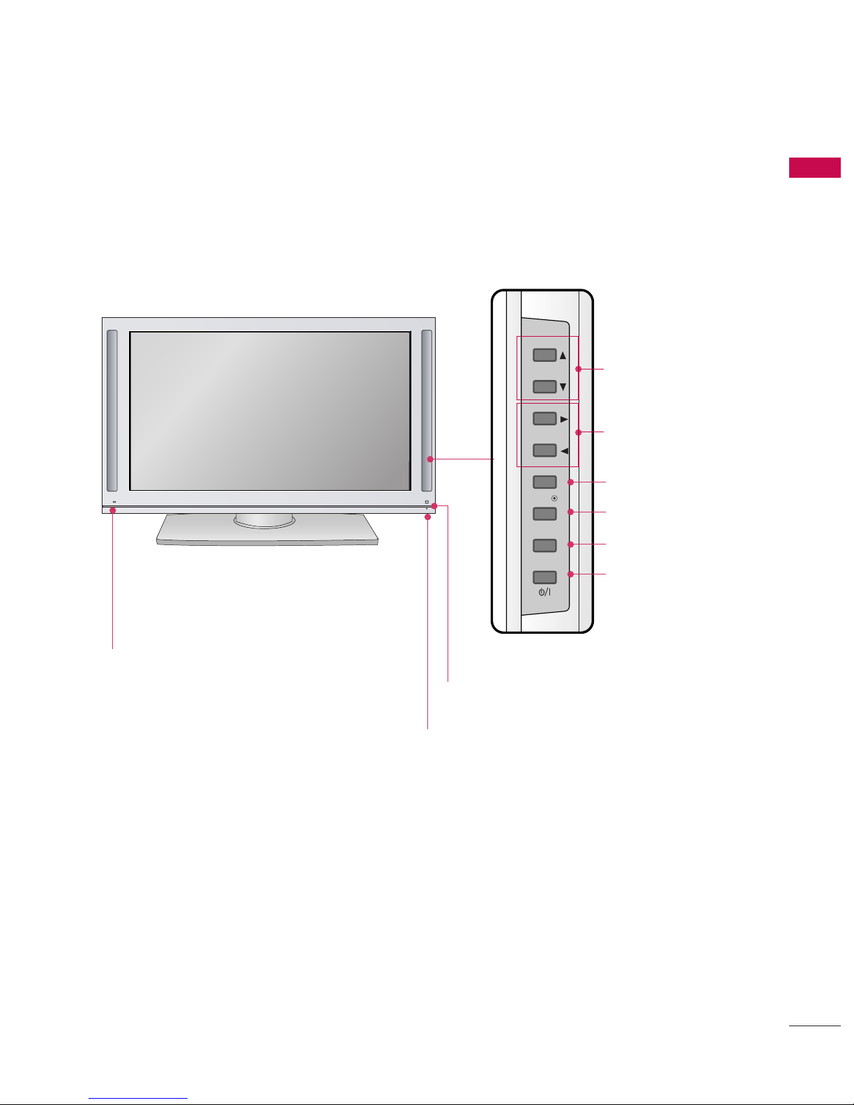
Front Panel Controls . . . . . . . . . . . . . . . . . . . . . . 5
Back Panel Information . . . . . . . . . . . . . . . . . . . . 6
Attaching the TV to a Wall . . . . . . . . . . . . . . . . . . 7
Back Cover for Wire Arrangement . . . . . . . . . . . . 8
Desktop Pe estal Installation . . . . . . . . . . . . . . . . 9
Swivel Stan . . . . . . . . . . . . . . . . . . . . . . . . . . . . . 9
Antenna Connection . . . . . . . . . . . . . . . . . . . . . . 10
EXTERNAL EQUIPMENT SETUP
HD Receiver Setup . . . . . . . . . . . . . . . . . . . . . . . . . . . . . . . . . . . . . . . . . . 11
DVD Setup . . . . . . . . . . . . . . . . . . . . . . . . . . . . . . . . . . . . . . . . . . . . . . . . . . . . . . 14
VCR Setup . . . . . . . . . . . . . . . . . . . . . . . . . . . . . . . . . . . . . . . . . . . . . . . . . . . . . . 16
Other A/V Source Setup . . . . . . . . . . . . . . . . . . . . . . . . . . . . . . . . . . 18
PC Setup . . . . . . . . . . . . . . . . . . . . . . . . . . . . . . . . . . . . . . . . . . . . . . . . . . . . . . . . 19
- Screen Setup for PC Mo e . . . . . . . . . . . . . . . . . . . . . . . . . 22
USB In Setup . . . . . . . . . . . . . . . . . . . . . . . . . . . . . . . . . . . . . . . . . . . . . . . . . . 24
External Stereo Setup . . . . . . . . . . . . . . . . . . . . . . . . . . . . . . . . . . . . . . 24
Digital Au io Output Setup . . . . . . . . . . . . . . . . . . . . . . . . . . . . . 25
WATCHING TV / PROGRAMME CONTROL
Remote Control Key Functions . . . . . . . . . . . . . .26
Turning on the TV . . . . . . . . . . . . . . . . . . . . . . . . 28
Initializing Setup . . . . . . . . . . . . . . . . . . . . . . . . . 28
Programme Selection . . . . . . . . . . . . . . . . . . . . . 29
Volume A justment . . . . . . . . . . . . . . . . . . . . . . 29
On-Screen Menus Selection an A justment . . 30
Factory Reset . . . . . . . . . . . . . . . . . . . . . . . . . . . . 31
Mo el Info . . . . . . . . . . . . . . . . . . . . . . . . . . . . . . 32
Auto Programme Tuning . . . . . . . . . . . . . . . . . . .33
Manual Programme Tuning . . . . . . . . . . . . . . . . . 35
Fine Tuning . . . . . . . . . . . . . . . . . . . . . . . . . . . . . 37
Assigning a Station Name . . . . . . . . . . . . . . . . . 38
Booster . . . . . . . . . . . . . . . . . . . . . . . . . . . . . . . . 39
Programme E it . . . . . . . . . . . . . . . . . . . . . . . . . .40
Input List . . . . . . . . . . . . . . . . . . . . . . . . . . . . . . . 42
Calling Up the Channel List . . . . . . . . . . . . . . . . 43
Input Source Selection . . . . . . . . . . . . . . . . . . . . 44
SIMPLINK . . . . . . . . . . . . . . . . . . . . . . . . . . . . . . 45
Key Lock . . . . . . . . . . . . . . . . . . . . . . . . . . . . . . . 47
DVR
Timeshift Mo e . . . . . . . . . . . . . . . . . . . . . . . . . . 48
Recor ing . . . . . . . . . . . . . . . . . . . . . . . . . . . . . . 51
Manual Recor ing . . . . . . . . . . . . . . . . . . . . . . . . 54
Recor e TV . . . . . . . . . . . . . . . . . . . . . . . . . . . . 55
Sche ule List . . . . . . . . . . . . . . . . . . . . . . . . . . . 59
HDD Format . . . . . . . . . . . . . . . . . . . . . . . . . . . . 60
Recor Quality . . . . . . . . . . . . . . . . . . . . . . . . . . 61
To Use the USB Device . . . . . . . . . . . . . . . . . . . 62
Photo List . . . . . . . . . . . . . . . . . . . . . . . . . . . . . . 63
Music List . . . . . . . . . . . . . . . . . . . . . . . . . . . . . . 67
EPG(ELECTRONIC PROGRAMME GUIDE)
Switch on/off EPG . . . . . . . . . . . . . . . . . . . . . . . 70
Select a programme . . . . . . . . . . . . . . . . . . . . . . 70
Button Function in NOW/NEXT Gui e Mo e . 71
Button Function in Exten e Description Box . 71
Button Function in 7 Days Gui e Mo e . . . . . . 72
PICTURE CONTROL
Watching PIP(Picture-In-Picture) . . . . . . . . . . . .73
Picture Size (Aspect Ratio) Control . . . . . . . . . .76
Preset Picture Settings
- Picture Mo e - Preset . . . . . . . . . . . . . . . . 77
- Auto Colour Tone Control
(Warm/Me ium/Cool) . . . . . . . . . . . . . . . .78
Manual Picture A justment
- Picture Mo e - User Option . . . . . . . . . . . 79
- Colour Tone - User Option. . . . . . . . . . . . .80
Brightness A justment . . . . . . . . . . . . . . . . . . . . . . 81
XD - Picture Improvement Technology . . . . . . . . . . . 82
A vance - Cinema . . . . . . . . . . . . . . . . . . . . . . . 83
A vance - Black( Darkness) Level . . . . . . . . . . 84
Picture Reset . . . . . . . . . . . . . . . . . . . . . . . . . . . . 85

CON EN S
3
After rea ing this manual, keep it han y for future reference.
SOUND & LANGUAGE CONTROL
Auto Volume Leveler ( Auto Volume) . . . . . . . . . 86
Preset Soun Settings- Soun Mo e . . . . . . . . 87
Soun Setting A justment - User Mo e . . . . . . . . 88
Balance . . . . . . . . . . . . . . . . . . . . . . . . . . . . . . . . .90
TV Speakers On/ Off Setup . . . . . . . . . . . . . . . . 91
I/II
- Stereo/Dual Reception . . . . . . . . . . . . . . . . . 92
- Speaker Soun Output Selection . . . . . . . . 92
Subtitle . . . . . . . . . . . . . . . . . . . . . . . . . . . . . . . . 93
TIME SETTING
Clock Setting . . . . . . . . . . . . . . . . . . . . . . . . . . . . 94
Auto On/ Off Timer Setting . . . . . . . . . . . . . . . .96
Sleep Timer Setting . . . . . . . . . . . . . . . . . . . . . . .97
Auto Shut-off Setting . . . . . . . . . . . . . . . . . . . . . .98
PARENTAL CONTROL / RATINGS
Set Passwor & Lock System . . . . . . . . . . . . . . . 99
Programme Blocking . . . . . . . . . . . . . . . . . . . . . 101
Parental Gui ance . . . . . . . . . . . . . . . . . . . . . . . 102
External Input Blocking . . . . . . . . . . . . . . . . . . . 103
TELETEXT
Switch On/Off . . . . . . . . . . . . . . . . . . . . . . . . . 104
Simple Text . . . . . . . . . . . . . . . . . . . . . . . . . . . . 104
TOP Text . . . . . . . . . . . . . . . . . . . . . . . . . . . . . . 104
Fastext . . . . . . . . . . . . . . . . . . . . . . . . . . . . . . . . 105
Special Teletext Functions . . . . . . . . . . . . . . . . 105
APPENDIX
Troubleshooting . . . . . . . . . . . . . . . . . . . . . . . . .106
Maintenance . . . . . . . . . . . . . . . . . . . . . . . . . . .108
Pro uct Specifications . . . . . . . . . . . . . . . . . . . 109
Programming the Remote Control . . . . . . . . . 110
IR Co es . . . . . . . . . . . . . . . . . . . . . . . . . . . . . . . 112
External Control Through RS-232C . . . . . . . . . 115
Open Source License . . . . . . . . . . . . . . . . . . . . 121

PREPARA ION
4
PREPARA ION
HOME MENU
his menu is a contents guide.
In Home Menu, you enter the Recorded V and the Guide of X-S UDIO, the X-S UDIO recording schedule,
Manual Recording, Photo List, Music List
TV
DVD
SIMPLINK
EXIT
VOL
Q.VIEW
PR
MARK
LIVE
TEXT
GUIDE
VCR
MODE
BRIGHT
MENU
MUTE
PAGE
INFO
i
PIP PR- PIP PR+
PIP INPUTSWAP
TIME
SHIFT
TIME
SHIFT
PIP
OK
D/A
INPUT
POWER
INPUT
Schedule GGpp..5599
DVR
GGpp..4488
Guide GGpp..7700
Photo List GGpp..6633
Music List GGpp..6677

PREPARA ION
5
FRON PANEL CON ROLS
■
This is a simplifie representation of the front panel. Image shown may be somewhat ifferent from your TV.
■
If your pro uct has a protection film attache , remove the film an then wipe the pro uct with a polishing
cloth.
PR
VOL
OK
MENU
INPUT
PROGRAMME
(EE,DD) Buttons
VOLUME
(FF,GG) Buttons
OK Button
MENU Button
INPU Button
POWER Button
Remote Control Sensor
Power/Standby Indicator
• illuminates re in stan by mo e.
• illuminates green when the set is
switche on.
Intelligent Eye
A justs picture
accor ing to the
surroun ing con-
itions.

PREPARATION
6
PREPARATION
BACK PANEL INFORMATION
■
Image shown may be somewhat different from your TV.
USB Input
S-VIDEO Input
Connect S-Video out from an S-
VIDEO device.
AUDIO/VIDEO Input
Connect audio/video out ut from
an external device to these jacks.
AV IN 2
L/
MONO
R
AUDIO
A
VIDEO
S-VIDEO
USB IN
ANTENNA
IN
HDMI/DVI IN
COMPONENT IN
VIDEO
AUDIO
RGB IN
RGB (PC) AUDIO
(RGB/DVI)
AV IN 1
VIDEO
S-VIDEO AUDIO
( )
RS-232C IN
(CONTROL & SERVICE)
REMOTE
CONTROL IN
DIGITAL
AUDIO
OUT
OPTICAL
AUDIO OUT
HDMI/DVI IN
Connect a HDMI signal.
Or DVI(VIDEO) signal to the this ort with a
HDMI to DVI cable.
RGB/AUDIO IN
Connect the out ut from a set to box or PC to
the a ro riate in ut ort.
RS-232C IN (CONTROL &SERVICE PORT
Connect to the RS-232C ort on a PC.
Remote Control Port
Connect your wired remote control.
ANTENNA IN
Connect antenna signals to this jack.
DIGITAL AUDIO OUT
Connect digital audio from various ty es of
equi ment. Note: In standby mode, these orts
do not work.
COMPONENT IN
Connect a com onent video/audio device to
these jacks.
AV (Audio/Video IN 1
Connect audio/video out ut from an external
device to these jacks.
S-VIDEO
Connect S-Video out from an S-VIDEO device.
AUDIO OUT
Connect an external am lifier or add a subwoofer
to your surround sound system.
Power Cord Socket
For o eration with AC ower.
Caution: Never attem t to o erate the TV on DC
ower.
1
6
7
8
9
10
2
3
4
5
ANTENNAANTENNA
ININ
HDMI/DVI INHDMI/DVI IN
2
1
COMPONENT INCOMPONENT IN
VIDEOVIDEO
AUDIOAUDIO
RGB INRGB IN
RGB (PC)RGB (PC) AUDIOAUDIO
(RGB/DVI)(RGB/DVI)
AV IN 1AV IN 1
VIDEOVIDEO
S-VIDEOS-VIDEO AUDIOAUDIO
MONO
()
RS-232C INRS-232C IN
(CONTROL & SERVICE)(CONTROL & SERVICE)
REMOTEREMOTE
CONTROL INCONTROL IN
DIGITALDIGITAL
AUDIOAUDIO
OUTOUT
OPTICALPTICAL
3
AUDIO OUTAUDIO OUT
124
78
356
9
10

PREPARA ION
7
A ACHING HE V O A WALL
AThis Feature is not available for all mo els.
ASet it up close to the wall so the product doesn’t fall over when it is pushed backwards.
Ahe instructions shown below is a safer way to set up the product, which is to fix it on the wall so the
product doesn’t fall over when it is pulled in the forward direction. It will prevent the product from
falling forward and hurting people. It will also prevent the product from damage caused by fall. Please
make sure that children don’t climb on or hang from the product.
Use the eye-bolts or TV brackets/bolts to fix the pro uct to the wall as shown in the picture.
(If your pro uct has the bolts in the eye-bolts position before inserting the eye-bolts, loosen the bolts.)
* Insert the eye-bolts or TV brackets/bolts an tighten them securely in the upper holes.
Secure the wall brackets with the bolts (not provi e as parts of the pro uct, must purchase separately) on
the wall. Match the height of the bracket that is mounte on the wall.
1
2
Use a stur y rope (not provi e as parts of the pro uct, must purchase separately) to tie the
pro uct. It is safer to tie the rope so it becomes horizontal between the wall an the pro uct.
3
3
2
1

PREPARA ION
8
PREPARA ION
Connect the cables as necessary.
To connect a itional equipment, see the EExxtteerrnnaall
EEqquuiippmmeennttSSeettuupp section.
Install the CCAABBLLEE MMAANNAAGGEEMMEENNTTas shown.
Bun le the cables using the supplie twist hol er.
(This Feature is not available for all mo els.)
Hol the CCAABBLLEE MMAANNAAGGEEMMEENNTTwith both
han s an pull it upwar .
NOTE
!
GG Do not hold the CABLE MANAGEMENT when moving the product.
- If the product is dropped, you may be injured or the product may be broken.
CABLE MANAGEMEN
WIS HOLDER
1
2
3
BACK COVER FOR WIRE ARRANGEMEN
■
Here shown may be somewhat ifferent from your TV.
How to remove the cable management

PREPARA ION
9
GGEnsure a equate ventilation by
following the clearance recom-
men ations.
CAUTION
DESK OP PEDES AL INS ALLA ION
For proper ventilation, allow a clearance of 4inches on all four sides from the wall.
4 inches
4 inches 4 inches
4 inches
Power Supply
Short-circuit
Breaker
GROUNDING
Ensure that you connect the earth groun wire to prevent
possible electric shock. If groun ing metho s are not possi-
ble, have a qualifie electrician install a separate circuit
breaker.
Do not try to groun the unit by connecting it to telephone
wires, lightening ro s, or gas pipes.
SWIVEL S AND
After installing the V, you can adjust the V set manually to the left
or right direction by 20 degrees to suit your viewing position.

10
PREPARA ION
ANTENNA
IN
HDMI/DVI IN
COMPONENT IN
VIDEO
AUDIO
RGB IN
RGB (PC) AUDIO
(RGB/DVI)
AV IN 1
VIDEO
S-VIDEO AUDIO
( )
RS-232C IN
(CONTROL & SERVICE)
REMOTE
CONTROL IN
DIGITAL
AUDIO
OUT
OPTICAL
AUDIO OUT
■o prevent the equipment damage, never plug in any power cords until you have finished connecting all equipment.
AN ENNA CONNEC ION
Wall Antenna Socket or Out oor Antenna without a
Cable Box Connections. For optimum picture quality,
a just antenna irection if nee e .
ANTENNA
IN
Multi-family Dwellings/Apartments
(Connect to wall antenna socket)
Single-family Dwellings /Houses
(Connect to wall jack for outdoor antenna)
Outdoor
Antenna
(VHF, UHF)
Wall
Antenna
Socket
RF Coaxial Wire (75 ohm)
GGThe TV will let you know when the analogue, cable, an igital programme scans are complete.
NOTE
!
ANTENNA
IN
■To improve the picture quality in a poor signal area, please purchase a signal amplifier an install properly.
■If the antenna nee s to be split for two TV’s, install a 2-Way Signal Splitter.
■If the antenna is not installe properly, contact your ealer for assistance.
Antenna
UHF
Signal
Amplifier
VHF

EXTERNAL EQUIPMENT SETUP
11
EXTERNAL EQUIPMENT SETUP
■To prevent the equipment damage, never plug in an power cords until ou have finished connecting all equipment.
HD RECEIVER SETUP
When connecting with a Component cables
Connect the video outputs (Y, PB, PR)of the digital set
top box to the CCOOMMPPOONNEENN IINN VVIIDDEEOO 11jacks on
the set. Match the jack colours.
(Y = green, PB= blue, and PR= red)
Connect the audio output of the digital set-top box to
the CCOOMMPPOONNEENN IINN AAUUDDIIOO 11jacks on the set.
urn on the digital set-top box.
(Refer to the owner’s manual for the digital set-top box.)
Select CCoommppoonneenntt 11input source using the IINNPPUU
button on the remote control.
If connected to CCOOMMPPOONNEENN IINN 22input, select
CCoommppoonneenntt 22input source.
2
1
Signal
480i
480p
576i
576p
720p
1080 i
1080p
Component 1/2
Yes
Yes
Yes
Yes
Yes
Yes
Yes
HDMI 1/2/3
No
Yes
No
Yes
Yes
Yes
Yes
3
4
RGB IN
RGB (PC)
COMPONENT INCOMPONENT IN
VIDEOVIDEO
AUDIOAUDIO
Y L RPBPR
COMPONENT IN
VIDEO
AUDIO
RGB IN
RGB (PC) AUDIO
(RGB/DVI)
COMPONENT IN
VIDEO
AUDIO
RGB IN
RGB (PC)
HDMI/DVI IN
COMPONENT IN
VIDEO
AUDIO
HDMI/DVI IN
RGB IN
AUDIO
(RGB/DVI)
12

EX ERNAL EQUIPMEN SE UP
12
EX ERNAL EQUIPMEN SE UP
When connecting with HDMI cable
Connect the igital set-top box to HHDDMMII//DDVVII IINN11, 22 or
33 jack on the set.
No separate au io connection is necessary.
Turn on the igital set-top box.
(Refer to the owner’s manual for the igital set-top box.)
Select HHDDMMII11,HHDDMMII22 or HHDDMMII33input source using the
IINNPPUUTTbutton on the remote control.
2
1
GGIf the igital set-top box supports Auto HDMI function, the
output resolution of the source evice will be automatically
set to 1280x720p.
GGIf the igital set-top box player oes not support Auto
HDMI, you nee to set the output resolution appropriately.
To get the best picture quality, a just the output resolution
of the source evice to 1920x1080i/1080p.
NOTE
!
3
4
RGB IN
RGB (PC)
COMPONENT IN
VIDEO
AUDIO
COMPONENT IN
VIDEO
AUDIO
RGB IN
RGB (PC) AUDIO
(RGB/DVI)
COMPONENT INCOMPONENT IN
VIDEOVIDEO
AUDAUDIO
RGB INRGB IN
RGB (PC)RGB (PC) AUDIO
(RGB/DVI)
HDMI/DVI INHDMI/DVI IN
2
1
HDMI-DTV OUTPUT
COMPONENT IN
VIDEO
AUDIO
HDMI/DVI IN
RGB IN
AUDIO
(RGB/DVI)
3
1

EX ERNAL EQUIPMEN SE UP
13
When connecting HDMI to DVI cable
RGB IN
RGB (PC)
COMPONENT IN
VIDEO
AUDIO
COMPONENT IN
VIDEO
AUDIO
RGB IN
RGB (PC) AUDIO
(RGB/DVI)
COMPONENT IN
VIDEO
AUDIO
RGB IN
RGB (PC)
HDMI/DVI IN
COMPONENT INCOMPONENT IN
VIDEOVIDEO
AUDIOAUDIO
HDMI/DVI INHDMI/DVI IN
1
RGB INRGB IN
RGB (PC) AUDIOAUDIO
(RGB/DVI)(RGB/DVI)
L R
DVI-DTV OUTPUT
2
3
Connect the DVI output of the igital set-top box to
the HHDDMMII//DDVVII IINN11, 22 or 33 jack on the set.
Connect the au io output of the igital set-top box to
the AAUUDDIIOO((RRGGBB//DDVVII)) jack on the set.
Turn on the igital set-top box. (Refer to the owner’s
manual for the igital set-top box.)
Select HHDDMMII11,HHDDMMII22 or HHDDMMII33input source with
using the IINNPPUUTTbutton on the remote control.
2
1
12
3
4

EX ERNAL EQUIPMEN SE UP
14
EX ERNAL EQUIPMEN SE UP
When connecting Component cables
RGB IN
RGB (PC)
S
COMPONENT INCOMPONENT IN
VIDEOVIDEO
AUDIOAUDIO
Y L RPBPR
COMPONENT IN
VIDEO
AUDIO
RGB IN
RGB (PC)
HDMI/DVI IN
COMPONENT IN
VIDEO
AUDIO
RGB IN
RGB (PC)
AV IN 1
VIDEO
AUDIO
( )
S-VIDEO
(C
DIGITAL
AUDIO
OUT
DIGITAL
AUDIO
OUT
DIGITAL
AUDIO
OUT
Component Input ports
o get better picture quality, connect a DVD player to the component input ports as shown below.
Component ports on the TV
YPBPR
Vi eo output ports
on DVD player
Y
Y
Y
Y
PB
B-Y
Cb
Pb
PR
R-Y
Cr
Pr
Connect the vi eo outputs (Y, PB, PR) of the DVD to the
CCOOMMPPOONNEENNTT IINN VVIIDDEEOO11jacks on the set.
Match the jack colours (Y = green, PB= blue, an PR= re ).
Connect the au io outputs of the DVD to the CCOOMMPPOO--
NNEENNTT IINN AAUUDDIIOO11jacks on the set.
Turn on the DVD player, insert a DVD.
Select CCoommppoonneenntt 11input source using the IINNPPUUTT
button on the remote control.
If connecte to CCOOMMPPOONNEENNTT IINN 22 input, select
CCoommppoonneenntt 22input source.
Refer to the DVD player's manual for operating instruc-
tions.
2
1
1 2
3
4
5
DVD SE UP

EX ERNAL EQUIPMEN SE UP
15
When connecting with an S-Video cable
RGB IN
RGB (PC)
COMPONENT IN
VIDEO
AUDIO
COMPONENT IN
VIDEO
AUDIO
RGB IN
RGB (PC)
HDMI/DVI IN
COMPONENT IN
VIDEO
AUDIO
RGB IN
RGB (PC)
AV IN 1
AV IN 1
VIDEOVIDEO
AUDIOAUDIO
MONO
()
S-VIDEOS-VIDEO
L R
S-VIDEO AUDIO
DIGITAL
AUDIO
OUT
DIGITAL
AUDIO
OUT
DIGITAL
AUDIO
OUT
12
Connect the S-VIDEO output of the DVD to the SS--VVIIDDEEOO
input on the set.
Connect the au io outputs of the DVD to the AAUUDDIIOO
input jacks on the set.
Turn on the DVD player, insert a DVD.
Select AAVV11input source using the IINNPPUUTTbutton on the
remote control.
If connecte to AAVV IINN 22input, select AAVV22input
source.
Refer to the DVD player's manual for operating instruc-
tions.
2
1
3
4
5
RGB IN
RGB (PC)
COMPONENT IN
VIDEO
AUDIO
COMPONENCOMPONENT IN
VIDEOVIDEO
AUDIO
RGB INRGB IN
RGB (PC)RGB (PC) A
(R
HDMI/DVI INHDMI/DVI IN
2
1
HDMI-DVD OUTPUT
COMPONENT IN
VIDEO
AUDIO
RGB IN
RGB (PC)
AV IN 1
VIDEO
AUDIO
( )
S-VIDEO
3
DIGITAL
AUDIO
OUT
DIGITAL
AUDIO
OUT
DIGITAL
AUDIO
OUT
1
When connecting HDMI cable
Connect the HDMI output of the DVD to the
HHDDMMII//DDVVII IINN11, 22 or 33jack on the set.
No separate au io connection is necessary.
Select HHDDMMII11,HHDDMMII22 or HHDDMMII33input source using the
IINNPPUUTTbutton on the remote control.
Refer to the DVD player's manual for operating instructions.
2
1
GGIf the DVD supports Auto HDMI function, the DVD output
resolution will be automatically set to 1280x720p.
GGIf the DVD oes not support Auto HDMI, you nee to set
the output resolution appropriately.
To get the best picture quality, a just the output resolution of
the DVD to 1920x1080i/1080p.
NOTE
!
3
4

EX ERNAL EQUIPMEN SE UP
16
EX ERNAL EQUIPMEN SE UP
VCR SE UP
When connecting with an antenna
■o avoid picture noise (interference), leave an adequate distance between the VCR and V.
■If the 4:3 picture format is used; the fixed images on the sides of the screen may remain visible on the
screen. his phenomenon is common to all manufacturers and in consequence the manufacturer’s warranty
does not cover the product bearing this phenomenon.
COMPONENT INCOMPONENT IN
VIDEOVIDEO
AUDIOAUDIO
RGB INRGB IN
RGB (PC)RGB (PC) AUDIO
(RGB/DVI)
AV IN 1
VIDEO
AUDIO
MONO
( )
S-VIDEO
COMPONENT IN
VIDEO
AUDIO
RGB IN
RGB (PC)
AV IN 1
VIDEO
AUDIO
( )
COMPONENT IN
VIDEO
AUDIO
RGB IN
RGB (PC)
AV IN 1
VIDEO
AUDIO
( )
S-VIDEO
ANTENNAANTENNA
ININ
L R
S-VIDEO VIDEO
OUTPUT
SWITCH
ANT IN
ANT OUT
RS-232C IN
(CONTROL & SERVICE)
REMOTE
CONTROL IN
AUDIO OUT
DIGITALDIGITAL
AUDIOAUDIO
OUTOUT
OPTICAL
DIGITAL
AUDIO
OUT
DIGITAL
AUDIO
OUT
HDMI/DVI IN
HDMI/DVI IN
HDMI/DVI IN
Wall Jack
Antenna
1
2
Connect the RF antenna out socket of the VCR to the AANNTTEENNNNAAIINN socket on the set.
Connect the antenna cable to the RF antenna in socket of the VCR.
Set VCR output switch to 3 or 4 an then tune TV to the same programme number.
Insert a vi eo tape into the VCR an press PLAY on the VCR. (Refer to the VCR owner’s manual.)
2
1
3
4

EX ERNAL EQUIPMEN SE UP
17
When connecting with an RCA cable
COMPONENT IN
VIDEO
AUDIO
RGB IN
RGB (PC)
COMPONENT IN
VIDEO
AUDIO
RGB IN
RGB (PC)
AV IN 1
AV IN 1
VIDEOVIDEO
AUDIOAUDIO
MONO
()
S-VIDEO
COMPONENT IN
VIDEO
AUDIO
RGB IN
RGB (PC)
AV IN 1
VIDEO
AUDIO
( )
S-VIDEO
L R
S-VIDEOVIDEO
OUTPUT
SWITCH
ANT IN
ANT OUT
ANTENNA
IN
DIGITAL
AUDIO
OUT
DIGITAL
AUDIO
OUT
AUDIO OUT
DIGITAL
AUDIO
OUT
HDMI/DVI IN
HDMI/DVI IN
HDMI/DVI IN
Connect the AAUUDDIIOO/VVIIDDEEOOjacks between TV an
VCR. Match the jack colours(Vi eo = yellow, Au io Left =
white, an Au io Right = re )
Insert a vi eo tape into the VCR an press PLAY on the
VCR. (Refer to the VCR owner’s manual.)
Select AAVV11input source using the IINNPPUUTTbutton on
the remote control.
If connecte to AAVV IINN22, select AAVV22input source.
1
GGIf you have a mono VCR, connect the au io cable from the
VCR to the AAUUDDIIOO LL((MMOONNOO))jack of the set.
NOTE
!
1
3
2
GGDo not connect to both Vi eo
an S-Vi eo at the same time. In
the event that you connect both
Vi eo an the S-Vi eo cables,
only the S-Vi eo will work.
CAUTION
GGThe picture quality is improve : ; compare to normal
composite (RCA cable) input.
NOTE
!
COMPONENT IN
VIDEO
AUDIO
RGB IN
RGB (PC)
COMPONENT IN
VIDEO
AUDIO
RGB IN
RGB (PC)
AV IN 1
VIDEO
AUDIO
( )
COMPONENT IN
VIDEO
OAUDIO
RGB IN
RGB (PC)
AV IN 1
AV IN 1
VIDEOVIDEO
AUDIOAUDIO
MONO
()
S-VIDEOS-VIDEO
L R
S-VIDEO VIDEO
OUTPUT
SWITCH
ANT IN
ANT OUT
ANTENNA
IN
DIGITAL
AUDIO
OUT
AUDIO OUT
DIGITAL
AUDIO
OUT
DIGITAL
AUDIO
OUT
HDMI/DVI IN
HDMI/DVI IN
HDMI/DVI IN
When connecting with an S-Video cable
Connect the S-VIDEO output of the VCR to the SS--VVIIDDEEOO
input on the set.
Connect the au io outputs of the VCR to the AAUUDDIIOO
input jacks on the set.
Insert a vi eo tape into the VCR an press PLAY on the
VCR. (Refer to the VCR owner’s manual.)
Select AAVV11input source using the IINNPPUUTTbutton on
the remote control.
If connecte to AAVV IINN 22input, select AAVV22input
source.
2
1
12
3
4

AV IN 2
R
USB IN
L R
VIDEO
EX ERNAL EQUIPMEN SE UP
18
EX ERNAL EQUIPMEN SE UP
O HER A/V SOURCE SE UP
Camcorder
Video Game Set
1
Connect the AAUUDDIIOO/VVIIDDEEOOjacks between TV an
external equipment. Match the jack colours
.(Vi eo = yellow, Au io Left = white,
an Au io Right = re )
Select AAVV22input source using the IINNPPUUTTbutton on the remote control.
If connecte to AAVV IINN11input, select AAVV11input source.
Operate the correspon ing external equipment.
1
2
3
This manual suits for next models
3
Table of contents
Other LG LCD TV manuals