LG 42PC1R Series User manual

PP//NNOO:: 3388228899UU00002255UU ((00771122--RREEVV0011))
LCD TV MODELS
32LC2R*
37LC2R*
42LC2R*
32HIZ20
37HIZ20
42HIZ20
32HIZ22
37HIZ22
42HIZ22
PLASMA TV MODELS
42PC1R*
42PC3R*
50PC1R*
PPlleeaassee rreeaadd IInnffoorrmmaattiioonn Maannuuaall iinncclluuddeedd
ttooggeetthheerr bbeeffoorree rreeaaddiinngg tthhiiss mmaannuuaall aanndd
ooppeerraattiinngg yyoouurr sseett..
Retain it for future reference.
Record model number and serial number of the set.
See the label attached on the back cover and quote
this information to your dealer when you require service.
OOWWEERR’’SS MMAAUUAALL
LCD TV PLASMA TV
Hotel_0025U 11/26/07 1:33 PM Page 1

Hotel_0025U 11/26/07 1:33 PM Page 2

ACCESSORIES
Ensure that the following accessories are included with your TV. If an accessory is missing, please contact the
dealer where you purchased the product.
2-Wall brackets 2-eye-bolts
2-bolts for stand assembly
(Refer p.11)
This feature is ot available
for all models.
2- V brackets
2-Wall brackets 2-bolts
Cable
Management
wister Holder
Arrange the wires
with the twister holder.
1
ACCESSORIES
FFoorr 4422PPCC11RR**,, 5500PPCC11RR**,, 4422PPCC33RR**
FFoorr 3322//3377//4422LLCC22RR**,,3377HHIIZZ2200,, 4422HHIIZZ2200,, 3377HHIIZZ2200,, 4422HHIIZZ2200,, 3322HHIIZZ2222,, 3377HHIIZZ2222,, 4422HHIIZZ2222
Batteries
OK
INPUT
TVTV
INPUT
PIPPR- PIPPR+ SWAP
PIPINPUT
DVD
ARC
EXIT
VOL
TIME
REVEAL
INDEX
Q.VIEW
MUTE
PR
SLEEP
LIST
I/II
MENU
TEXT PIP SIZE
POSTION
VCR
POWER
123
456
789
*
0
FAV
?
Remote Control Power Cord
Polishing Cloth
Polish the screen with the cloth
(Option)
*Slightly wipe stained spot on the exterior only with
the cleansing cloths for the product exterior if
there is stain or fingerprint on surface of the exterior.
Do not wipe roughly when removing stain. Please
be cautious of that excessive power may cause
scratch or discoloration.
Hotel_0025U 11/26/07 1:33 PM Page 1

2
CON EN S
CON EN S
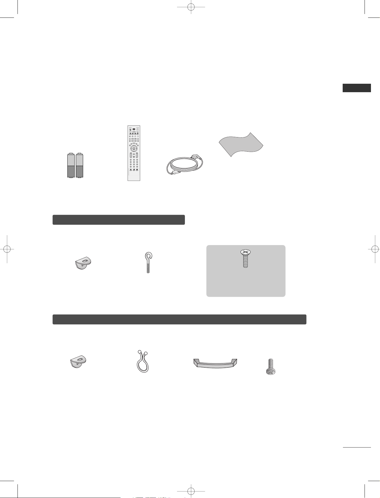
AACCCCEESSSSOORRIIEESS . . . . . . . . . . . . . . . . . . . . . . . . . . . . . . . . . . . . . . . . . . . . . . . . . . .1
IN RODUC ION
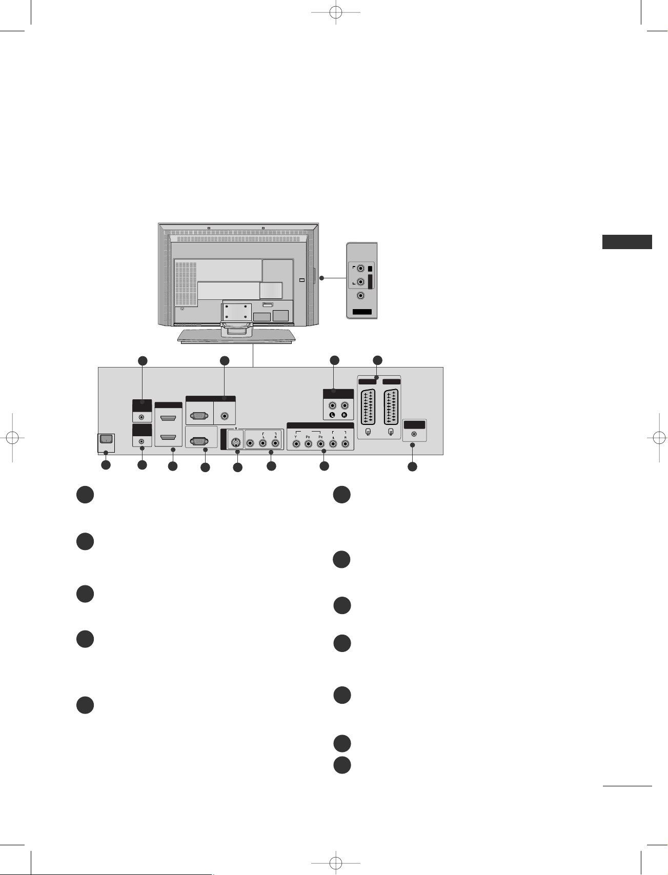
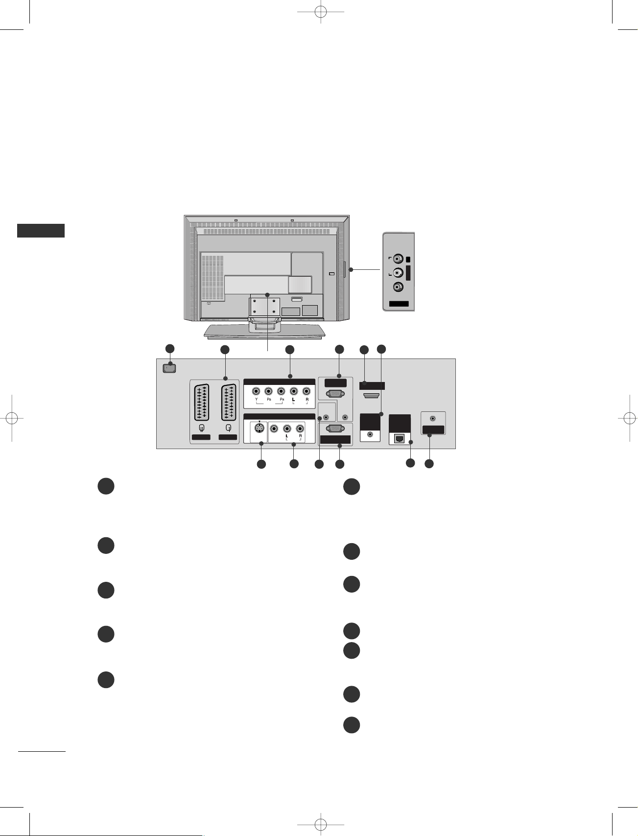
Co trols / Co ectio Optio s . . . . . . . . . . . . . . . . . . . . . . . . . .4-8
Remote Co trol Key Fu ctio s/
I stalli g Batteries
. . . . . . . . . . . . . . . . . . . . . . . . . . . . . . . . . . . . . . . . .9-10
VMENU
O Scree Me us Selectio a d Adjustme t . . . . .34
SSeettttiigg uupp TTVV ssttaattiiooss
Auto programme tu i g . . . . . . . . . . . . . . . . . . . . . . . . . . . . . . .35
Ma ual programme tu i g . . . . . . . . . . . . . . . . . . . . . . . . . . . .36
Fi e tu i g . . . . . . . . . . . . . . . . . . . . . . . . . . . . . . . . . . . . . . . . . . . . . . . . . .37
Assig i g a statio ame . . . . . . . . . . . . . . . . . . . . . . . . . . . . . . .38
Booster (Optio ) . . . . . . . . . . . . . . . . . . . . . . . . . . . . . . . . . . . . . . . . .39
Programme edit . . . . . . . . . . . . . . . . . . . . . . . . . . . . . . . . . . . . . . . . . . .40
Favourite programme
. . . . . . . . . . . . . . . . . . . . . . . . . . . . . . . . . . . .
41
Calli g the programme table
. . . . . . . . . . . . . . . . . . . . . . . . .
42
PPiiccttuurree MMeeuu
PSM (Picture Status Memory) . . . . . . . . . . . . . . . . . . . . . .43
Picture Adjustme t (PSM-User optio ) . . . . . . . . .44
CSM (Colour Status Memory) . . . . . . . . . . . . . . . . . . . . . .45
Ma ual Colour Temperature Co trol
(CSM - User optio ) . . . . . . . . . . . . . . . . . . . . . . . . . . . . . . . . . . . .46
Fu ctio . . . . . . . . . . . . . . . . . . . . . . . . . . . . . . . . . . . . . . . . . . .47
Adva ced . . . . . . . . . . . . . . . . . . . . . . . . . . . . . . . . . . . . . . . . . . . . . . . . . . . .48
Reset . . . . . . . . . . . . . . . . . . . . . . . . . . . . . . . . . . . . . . . . . . . . . . . . . . . . . . . . . . .49
SSoouudd MMeeuu
SSM (Sou d Status Memory) . . . . . . . . . . . . . . . . . . . . . . .50
Sou d Freque cy Adjustme t
(SSM - User optio ) . . . . . . . . . . . . . . . . . . . . . . . . . . . . . . . . . . . .51
AVL (Auto Volume Leveler) . . . . . . . . . . . . . . . . . . . . . . . . . . .52
Bala ce Adjustme t . . . . . . . . . . . . . . . . . . . . . . . . . . . . . . . . . . . . .52
Speaker . . . . . . . . . . . . . . . . . . . . . . . . . . . . . . . . . . . . . . . . . . . . . . . . . . . . . . .53
Stereo/Dual Receptio . . . . . . . . . . . . . . . . . . . . . . . . . . . . . . . . .54
NICAM Receptio . . . . . . . . . . . . . . . . . . . . . . . . . . . . . . . . . . . . . . . .55
Speaker Sou d Output Selectio . . . . . . . . . . . . . . . . . .55
TTiimmee MMeeuu
Clock Setup . . . . . . . . . . . . . . . . . . . . . . . . . . . . . . . . . . . . . . . . . . . . . . . . .56
O /Off Time . . . . . . . . . . . . . . . . . . . . . . . . . . . . . . . . . . . . . . . . . . . . . . .57
Auto Sleep . . . . . . . . . . . . . . . . . . . . . . . . . . . . . . . . . . . . . . . . . . . . . . . . . .58
Sleep Timer . . . . . . . . . . . . . . . . . . . . . . . . . . . . . . . . . . . . . . . . . . . . . . . . .59
SSppeecciiaall MMeeuu
Child Lock . . . . . . . . . . . . . . . . . . . . . . . . . . . . . . . . . . . . . . . . . . . . . . . . . . .60
ISM (Image Sticki g Mi imizatio )
Method (Optio ) . . . . . . . . . . . . . . . . . . . . . . . . . . . . . . . . . . . . . . . . .61
Low Power (Optio ) . . . . . . . . . . . . . . . . . . . . . . . . . . . . . . . . . . . . .62
XD Demo . . . . . . . . . . . . . . . . . . . . . . . . . . . . . . . . . . . . . . . . . . . . . . . . . . . .62
INS ALLA ION
U foldi g The Base Sta d . . . . . . . . . . . . . . . . . . . . . . . . . . . . . . . . . .11
Basic Co ectio /
How to Remove the Cable Ma ageme t . . . . . . . . . . .12-13
How to joi the product assembly to the wall
to protect the set tumbli g . . . . . . . . . . . . . . . . . . . . . . . . . . . . . . . . . .14
Sta d I stallatio . . . . . . . . . . . . . . . . . . . . . . . . . . . . . . . . . . . . . . . . . . . . . . . .15
CONNEC IONS & SE UP
A te a Co ectio . . . . . . . . . . . . . . . . . . . . . . . . . . . . . . . . . . . . . . . . . . . .16
VCR Setup . . . . . . . . . . . . . . . . . . . . . . . . . . . . . . . . . . . . . . . . . . . . . . . . . . . . . .17-18
Exter al Equipme t Co ectio s
. . . . . . . . . . . . . . . . . . . . . . . .19
DVD Setup . . . . . . . . . . . . . . . . . . . . . . . . . . . . . . . . . . . . . . . . . . . . . . . . . . . .20-21
STB(SET-TOP BOX) Setup . . . . . . . . . . . . . . . . . . . . . . . . . . . . .22-23
PC Setup . . . . . . . . . . . . . . . . . . . . . . . . . . . . . . . . . . . . . . . . . . . . . . . . . . . . . .24-26
TURNING THE TV ON . . . . . . . . . . . . . . . . . . . . . . . . . . . . . . . . . . . . . . . . .27
SPECIAL FUNC IONS
PPIIPP ((PPiiccttuurree--II--PPiiccttuurree)) // DDoouubbllee WWiiddooww // PPOOPP
Watchi g PIP/Double Wi dow/POP . . . . . . . . . . . . . .28
Programme Selectio for Sub Picture . . . . . . . . . . . .28
I put Source Selectio for Sub Picture . . . . . . . . .29
Sub Picture Size Adjustme t (PIP mode o ly)29
Movi g the Sub Picture (PIP mode o ly) . . .29
Adjusti g PIP Tra spare cy (PIP mode o ly) 29
Swappi g betwee mai a d sub pictures . . .30
POP
(Picture-out-of-Picture: Programme Sca ) . . .30
TTeelleetteexxtt
Teletext La guage Selectio (Optio ) . . . . . .31
Switch o /off . . . . . . . . . . . . . . . . . . . . . . . . .31
SIMPLE Text . . . . . . . . . . . . . . . . . . . . . . . . . .31
TOP Text . . . . . . . . . . . . . . . . . . . . . . . . . . . . .32
FASTEXT . . . . . . . . . . . . . . . . . . . . . . . . . . . . .32
Special Teletext Fu ctio s . . . . . . . . . . . . . . .33
Hotel_0025U 11/26/07 1:33 PM Page 2

3
CON EN S
VMENU
SSccrreeee MMeeuu
Auto Co figure (RGB [PC] mode o ly) . . . . . . . . . . . .63
Ma ual Co figure . . . . . . . . . . . . . . . . . . . . . . . . . . . . . . . . . . . . . . . .64
Setti g the Picture Format . . . . . . . . . . . . . . . . . . . . . .65-66
Selecti g Wide VGA/XGA mode . . . . . . . . . . . . . . . . . . .67
I itializi g
(Reset to origi al factory setti gs) . . . . . . . . . . . . . . . .67
APPENDIX
Exter al Co trol Device Setup
. . . . . . . . . . . . . . . . . . . . . .
68-74
IR Codes
. . . . . . . . . . . . . . . . . . . . . . . . . . . . . . . . . . . . . . . . . . . . . . . . . . . . . . .
75
Remote co trol IR codes
. . . . . . . . . . . . . . . . . . . . . . . . . . . . . . . . . .
76
Programmi g the Remote
. . . . . . . . . . . . . . . . . . . . . . . . . . . . . . . . .
77
Programmi g code
. . . . . . . . . . . . . . . . . . . . . . . . . . . . . . . . . . . . .
78-79
Troubleshooti g Checklist
. . . . . . . . . . . . . . . . . . . . . . . . . . . .
80-81
Mai te a ce
. . . . . . . . . . . . . . . . . . . . . . . . . . . . . . . . . . . . . . . . . . . . . . . . . .
82
Product Specificatio s
. . . . . . . . . . . . . . . . . . . . . . . . . . . . . . . .
83-84
Hotel_0025U 11/26/07 1:33 PM Page 3

4
IN RODUC ION
IN RODUC ION
This is the front panel of models 4422PPCC33RR* TVs.
PRPR
VOLOL
OKOK
MENUMENU
INPUTINPUT
Remote Control Sensor
Power/Standby Indicator
• illuminates red in standby mode.
• illuminates white when the set is switched on.
PROGRAMME Buttons
VOLUME Buttons
OK Button
ME U Button
I PUT Button
POWER Button
CO TROLS
This is the front panel of models 4422//5500PPCC11RR*TVs.
■
This is a simplified represe tatio of a fro t pa el. Here show may be somewhat differe t from your TV.
Front Panel Controls
PR
VOL
OK
MENU
INPUT
PROGRAMME Buttons
VOLUME Buttons
ME U Button
OK Button
I PUT Button
POWER Button
PR
VOL
OK
MENU
INPUT
Power/Standby Indicator
• illuminates red in standby mode.
• illuminates white when the set is
switched on.
PR
VOL
OK
MENU
INPUT
<Front Panel >
<Side Panel >
Hotel_0025U 11/26/07 1:33 PM Page 4

5
IN RODUC ION
CO ECTIO OPTIO
AC IN
RS-232C INRS-232C IN
(CONTROL(CONTROL
&
SERSERVICEVICE)
ANTENNA
IN
AV 1V 1 AV 2V 2
AUDIO OUT
VARIABLEARIABLE
RGB INRGB IN
VIDEOVIDEO
AUDIOAUDIO
COMPONENTCOMPONENT IN
AV IN 4V IN 4
L/MONO
R
AUDIOAUDIO
VIDEOVIDEO
MONO
()
AUDIOAUDIO
VIDEOVIDEO
S-VIDEOS-VIDEO
AV IN 3
RGB
(PC/DTV)(PC/DTV)
AUDIO
(RGB/DVI)
2
1 (DVI)1 (DVI)
HDMI INHDMI IN
CONTROL IN
REMOTE
This is the back panel of models 4422PPCC11RR*,5500PPCC11RR*,4422PPCC33RR*TVs.
Back Connection Panel
AUDIO Input
Co ectio s are available for liste i g
stereo sou d from a exter al device.
VIDEO Input
Co ects the video sig al from a video
device.
RGB/Audio Input
Co ect the mo itor output from a PC/DTV to
the appropriate i put port.
Variable Audio Output
Co ect a exter al amplifier or add a sub-
woofer to your surrou d sou d system.
Euro Scart Socket (AV1/AV2)
Co ect scart socket i put or output from a
exter al device to these jacks.
Power Cord Socket
This TV operates o a AC power. The voltage
is i dicated o the Specificatio s page. Never
attempt to operate the TV o DC power.
Remote Control Port
HDMI Input
Co ect a HDMI sig al to HDMI IN.
Co ect DVI(VIDEO) sig al to HDMI/DVI port
with DVI to HDMI cable.
RS-232C Input(CO TROL&SERVICE)Port
Co ect the serial port of the co trol devices
to the RS-232C jack.
S-Video Input
Co ect S-Video out from a S-VIDEO device.
Audio/Video Input
Co ect audio/video output from a exter al
device to these jacks.
Component Input
Co ect a compo e t video/audio device to
these jacks.
Antenna Input
1
2
3
4
5
6
7
8
9
10
11
4321
7 8 9 10 11
65
(except 42PC3R*)
Hotel_0025U 11/26/07 1:33 PM Page 5

6
IN RODUC ION
CO TROLS
This is the front panel of models 3322//3377//4422LLCC22RR*, 3377HHIIZZ2200,, 4422HHIIZZ2200,, 3377HHIIZZ2222,, 4422HHIIZZ2222TVs.
■
This is a simplified represe tatio of a fro t pa el. Here show may be somewhat differe t from your TV.
PR
VOL
OK
MENU
INPUT
R
/I
Remote Control Sensor
Power/Standby Indicator
• illuminates red in standby mode.
• illuminates white when the set is switched on.
PROGRAMME Buttons
VOLUME Buttons
OK Button
ME U Button
I PUT Button
POWER Button
Clock LED
I TRODUCTIO
<Front Panel >
<Side Panel >
Hotel_0025U 11/26/07 1:33 PM Page 6

7
IN RODUC ION
CO ECTIO OPTIO
This is the back panel of models 3322//3377//4422LLCC22RR*, 3377HHIIZZ2200,,4422HHIIZZ2200 TVs.
Back Connection Panel
AUDIO Input
Co ectio s are available for liste i g
stereo sou d from a exter al device.
VIDEO Input
Co ects the video sig al from a video
device.
AC IN
AV IN 4
V IN 4
AUDIO
AUDIO
VIDEO
VIDEO
L/MONO
R
AC IN
AV 1
V 1
AV 2
V 2
COMPONENT
COMPONENT
IN
AV IN 3
MONO
()
RGB
(PC/DTV)
(PC/DTV)
RS-232C IN
RS-232C IN
(CONTROL
&
SERVICE)
VARIABLE
ARIABLE
AUDIO OUT
ANTENNA
IN
HDMI IN
HDMI IN
1(DVI)
1(DVI)
RGB IN
RGB IN
AUDIO
(RGB/DVI)
VIDEO
VIDEO
S-VIDEO
S-VIDEO
REMOTE
REMOTE
COMTROL
COMTROL
IN
SPEAKER
SPEAKER
OUTPUT
OUTPUT
(MONO)
(MONO)
2
AUDIO
AUDIO
AUDIO
AUDIO
VIDEO
VIDEO
RGB/Audio Input
Co ect the mo itor output from a PC/DTV
to the appropriate i put port.
Variable Audio Output
Co ect a exter al amplifier or add a sub-
woofer to your surrou d sou d system.
Euro Scart Socket (AV1/AV2)
Co ect scart socket i put or output from a
exter al device to these jacks.
Power Cord Socket
This TV operates o a AC power. The voltage
is i dicated o the Specificatio s page. Never
attempt to operate the TV o DC power.
Remote Control Port
HDMI Input
Co ect a HDMI sig al to HDMI IN.
Co ect DVI(VIDEO) sig al to HDMI/DVI
port with DVI to HDMI cable.
RS-232C Input(CO TROL&SERVICE)Port
Co ect the serial port of the co trol devices
to the RS-232C jack.
S-Video Input
Co ect S-Video out from a S-VIDEO device.
Audio/Video Input
Co ect audio/video output from a exter al
device to these jacks.
Component Input
Co ect a compo e t video/audio device to
these jacks.
Antenna Input
SPEAKER OUTPUT (MO O)
The pho e socket for a Hi-Fi amplifier system
is o this jacks.
10
9
78
32
1
6
5
11
1
2
3
4
5
6
7
8
9
10
11
12
4
12
Hotel_0025U 11/26/07 1:33 PM Page 7

REMOTE
CONTROL IN
AUDIO IN
(RGB/DVI)
AC IN
AV 1 AV 2V 2
MONO
()
AUDIOAUDIO
RGB INRGB IN
(PC/DTV)(PC/DTV)
RS-232C INRS-232C IN
(CONTROL(CONTROL
&
SERSERVICE)VICE)
HDMI/DVI INHDMI/DVI IN
ANTENNAANTENNA
IN
SPEAKER
OUTPUT
(MONO)
VIDEOVIDEO
S-VIDEOS-VIDEO
AV IN 3
VIDEOVIDEO
AUDIOAUDIO
COMPONENT IN
AV IN 4V IN 4
AUDIOAUDIOVIDEOVIDEO
L/L/MONOMONO
R
AC IN
RJP
INTERFACE
8
I TRODUCTIO
IN RODUC ION
CO ECTIO OPTIO
This is the back panel of models 3322HHIIZZ2222,, 3377HHIIZZ2222,, 4422HHIIZZ2222TVs.
Back Connection Panel
AUDIO Input
Co ectio s are available for liste i g
stereo sou d from a exter al device.
VIDEO Input
Co ects the video sig al from a video
device.
Power Cord Socket
This TV operates o a AC power. The voltage is
i dicated o the Specificatio s page. Never
attempt to operate the TV o DC power.
Euro Scart Socket (AV1/AV2)
Co ect scart socket i put or output from a
exter al device to these jacks.
Component Input
Co ect a compo e t video/audio device to
these jacks.
Speaker out (Mono)
The pho e socket for a Hi-Fi amplifier system is
o this jacks.
RGB/Audio Input
Co ect the mo itor output from a PC/DTV to
the appropriate i put port.
HDMI Input
Co ect a HDMI sig al to HDMI IN(or HDMI/DVI
IN). Co ect DVI(VIDEO) sig al to HDMI/DVI(or
HDMI/DVI IN) port with DVI to HDMI cable.
S-Video Input
Co ect S-Video out from a S-VIDEO device.
Audio/Video Input
Co ect audio/video output from a exter al
device to these jacks.
Remote Control Port
RS-232C Input (CO TROL&SERVICE) Port
Co ect the serial port of the co trol devices to
the RS-232C jack.
RJP Input (Available for 32/37/42HIZ22)
Co ect co trol li e (RJ45) for RJP(Remote Jack pack)
Antenna Input
Co ect over-the-air sig als to this jack.
78
3
1254
10
9
6
12
11
1
2
3
4
5
6
7
8
9
10
11
12
Hotel_0025U 11/26/07 1:33 PM Page 8

9
IN RODUC ION
REMOTE CO TROL KEY FU CTIO S
OK
INPUT
TVTV
INPUT
PIP PR- PIP PR+ SWAP
PIP INPUT
DVD
ARC
EXIT
VOL
TIME
REVEAL
INDEX
Q.VIEW
MUTE
PR
SLEEP
LIST
I/II
MENU
TEXT PIP SIZE
POSTION
VCR
POWER
123
456
789
*0
FAV
?
POWER
TV I PUT
I PUT
ARC
Brightness
adjustment
PIP
SIZE
POSITIO
PIP PR - /+
SWAP
PIP I PUT
Coloured
buttons
VCR/DVD
control buttons
EXI
LIS
MENU
I/II
SLEEP
Switches the set o from sta dby or off to sta dby.
Retur s from AV 1 ,AV 2 ,S-Video2,AV 3 , AV 4 (except
42PC3R*), Component,RGB,HDMI1/DVI or
HDMI 2 (or HDMI/DVI IN)to the TV mode.
Switches
the set o from sta dby.
If you press the butto o ce, the i put source OSD will
appear o scree as show . Press the DD/ EEbutto a d the
OOKKbutto to select the desired i put source (TV, AV 1 ,
AV 2 ,S-Video2,AV 3 , AV 4 (except 42PC3R*), Component,
RGB,HDMI1/DVI or HDMI 2 (or HDMI/DVI IN)).
Selects your desired picture format.
Adjusts scree bright ess.
It retur s to the default setti gs bright ess by cha gi g
mode source.
Switches the sub picture PIP, DW, POP or off mode.
Adjusts the sub picture size.
Moves the sub picture.
Selects a programme for the sub picture.
Excha ges the mai /sub images i PIP/Doubel wi dow mode.
Selects the i put source for the sub picture i PIP/Doubel
wi dow mode.
These butto s are used for teletext (o ly TTEELLEETTEEXXTT
models) or PPrrooggrraammmmee eeddiitt.
Co trols some video cassette recorders or DVD players
whe you have already selected DVD or VCR mode butto .
Clears all o -scree displays a d retur s to TV viewi g
from a y me u.
Displays the programme table.
Selects a me u.
Selects the sou d output.
Sets the sleep timer.
Hotel_0025U 11/26/07 1:33 PM Page 9

10
IN RODUC ION
REMOTE CO TROL KEY FU CTIO S
• Open the battery compartment cover on the back side and insert the
batteries with correct polarity.
• Install two 1.5V alkaline batteries of AA type. Don’t mix used batteries
with new batteries.
I STALLI G BATTERIES
I TRODUCTIO
OK
INPUT
TVTV
INPUT
PIP PR- PIP PR+ SWAP
PIP INPUT
DVD
ARC
EXIT
VOL
TIME
REVEAL
INDEX
Q.VIEW
MUTE
PR
SLEEP
LIST
I/II
MENU
TEXT PIP SIZE
POSTION
VCR
POWER
123
456
789
*0
FAV
?
1
1
1
MODE Selects the remote operati g modes.
TELETEXT
BUTTO S
These butto s are used for teletext.
For further details, see the ‘Teletext’ sectio .
THUMBSTICK
(Up/Down/Left
Right)
OK
Allows you to avigate the o -scree me us a d adjust
the system setti gs to your prefere ce.
Accepts your selectio or displays the curre t mode.
VOLUME UP
/DOW
Q.VIEW
MU E
Programme
UP/DOW
0~9 number
button
FAV
*
Adjusts the volume.
Retur s to the previously viewed programme.
Switches the sou d o or off.
Selects available programmes.
Selects a programme.
Selects umbered items i a me u.
Displays the selected favourite programme.
No fu ctio
Hotel_0025U 11/26/07 1:33 PM Page 10

11
INS ALLA ION
U FOLDI G THE BASE STA D (42PC1R
*
, 42PC3R
*
)
INS ALLA ION
■
This feature is ot available for all models.
Figures show here may be slightly differe t from your set.
WWhhee cclloossiigg tthhee ssttaadd ffoorr ssttoorraaggee
First remove the screws i the holes (B) o the bottom
of the sta d. A d the pull two Hooks (D) of the sta d bottom
a d fold the sta d i to the back of the set.
After foldi g, push two Locks (A) of the sta d bottom outward.
NO E
!
■Place the set with the scree faci g dow o a cushio or soft cloth as show i Figure 1.
Before u foldi g the sta d, please make sure two locks (A) o the bottom of the sta d push outward.
■Pull the sta d out as show above i Figures 2 ~3.
After u foldi g the sta d, please i sert a d tighte the screws i the holes (B) o the bottom of the sta d.
■Whe co ecti g cables to the set, do ot dise gage the lock (C).
This may cause the set to fall, causi g serious bodily i jury a d serious damage to the set.
A
D
A
C
B
B
1
3 4
2
Hotel_0025U 11/26/07 1:33 PM Page 11

12
INS ALLA ION
BASIC CO ECTIO (
PDP TV models)
I STALLATIO
Arra ge the cables as show picture.
Hold the CCAABBLLEE MMAANNAAGGEEMMEENNTT with both
ha ds a d push it as show .
Co ect the cables as ecessary.
To co ect a additio al equipme t, see the
EExxtteerraall eeqquuiippmmeettCCooeeccttiiooss sectio .
Rei stall the CCAABBLLEE MMAANNAAGGEEMMEENNTTas
show .
1
2
3
CABLE MA AGEME T
■These models have two cable arra geme t methods accordi g to the sta d type.
Stand type 1
Stand type 2
Hotel_0025U 11/26/07 1:33 PM Page 12

13
INS ALLA ION
BASIC CO ECTIO (
LCD TV models)
Hold the CCAABBLLEE MMAANNAAGGEEMMEENNTTwith both
ha ds a d pull it upward.
NO E
!
GG Do ot hold the CCAABBLLEE MMAANNAAGGEEMMEENNTT whe movi g the product.
If the product is dropped, you may be i jured or the product may be broke .
HOW TO REMOVE THE CABLE MA AGEME T (
LCD TV models)
Co ect the cables as ecessary.
After co ecti g the cables eatly, arra ge
the cables to the Cable Holder.
To co ect a additio al equipme t, see the
EExxtteerraall eeqquuiippmmeettCCooeeccttiiooss sec-
tio .
1
I stall the CCAABBLLEE MMAANNAAGGEEMMEENNTT
as show .
2
Bu dle the cables usi g the supplied
twister holder.
3
SWIVEL STA D
- The TV ca be co ve ie tly swiveled o its sta d 30° to
the left or right to provide the optimum viewi g a gle.
- This feature is ot available for all models.
Hotel_0025U 11/26/07 1:33 PM Page 13

14
INS ALLA ION
HOW TO JOI THE PRODUCT ASSEMBLY TO THE WALL TO
PROTECT THE SET TUMBLI G
I STALLATIO
2
1
■Set it up close to the wall so the product does ’t fall over whe it is pushed backwards.
■The i structio s show below is a safer way to set up the product, which is to fix it o the wall so the
product does ’t fall over whe it is pulled i the forward directio . It will preve t the product from falli g
forward a d hurti g people. It will also preve t the product from damage caused by fall. Please make sure
that childre do ’t climb o or ha g from the product.
or
3Use a sturdy rope ( ot provided as parts of the product, must purchase separately) to tie the product. It is
safer to tie the rope so it becomes horizo tal betwee the wall a d the product.
Use the eye-bolts or TV brackets/bolts to fix the product to the wall as show i the picture.
(If your product has the bolts i the eye-bolts positio before i serti g the eye-bolts, loose the bolts.)
* I sert the eye-bolts or TV brackets/bolts a d tighte them securely i the upper holes.
Secure the wall brackets with the bolts ( ot provided as parts of the product, must purchase separately) o
the wall. Match the height of the bracket that is mou ted o the wall.
NO E
!
GG Whe movi g the product to a other place u do the ropes first.
GG Use a product holder or a cabi et that is big a d stro g e ough for the size a d weight of the product.
GG To use the product safely make sure that the height of the bracket that is mou ted o the wall is same as
that of the product.
2
3
1
1
3
2
Hotel_0025U 11/26/07 1:33 PM Page 14

15
INS ALLA ION
STA D I STALLATIO
Desktop Pedestal Installation
PR
VOL
OK
MENU
INPUT
For proper ve tilatio , allow a cleara ce of 4” o each side a d from the wall.
Wall Mount: Horizontal installation
For proper ve tilatio , allow a cleara ce of 4" o each side a d from the wall. Detailed i stallatio i struc-
tio s are available from your dealer, see the optio al Tilt Wall Mou ti g Bracket I stallatio a d Setup Guide.
GGRROOUUNNDDIINNGG
E sure that you co ect the earth grou d wire to preve t
possible electric shock. If grou di g methods are ot
possible, have a qualified electricia i stall a separate circuit
breaker. Do ot try to grou d the u it by co ecti g it to
telepho e wires, lighte i g rods, or gas pipes.
Power
Supply
Short-circuit
Breaker
■The TV ca be i stalled i various ways such as o a wall, or o a desktop etc.
■The TV is desig ed to be mou ted horizo tally.
<<OOllyy 4422PPCC11RR*,, 4422PPCC33RR*>>
Remove two screws of the backside of the set before
i stalli g the wall mou ti g bracket.
Hotel_0025U 11/26/07 1:33 PM Page 15

16
CONNEC IONS & SE UP
CONNEC IONS & SE UP
A TE A CO ECTIO
■To preve t the equipme t damage, ever plug i a y power cords u til you have fi ished co ecti g all equipme t.
■For optimum picture quality, adjust a te a directio .
■A a te a cable a d co verter are ot supplied.
■I poor sig al areas, to get better picture quality,
i stall a sig al amplifier to the a te a as show
to the right.
■If sig al eeds to be split for two TVs, use a
a te a sig al splitter for co ectio . SSiiggnnaall
AAmmpplliiffiieerr
UHF
VHF
ANTENNA
IN
Multi-family Dwellings/Apartments
(Connect to wall antenna socket)
Single-family Dwellings /Houses
(Connect to wall jack for outdoor antenna)
Outdoor Antenna
Wall Antenna Socket
VHF Antenna
UHF Antenna
RF Coaxial Wire (75 ohm)
Turn clockwise to tighten.
ANTENNAANTENNA
IN
ANTENNA
IN
ANTENNA
ANTENNA
IN
ANTENNA
IN
Hotel_0025U 11/26/07 1:33 PM Page 16

17
CONNEC IONS & SE UP
VCR SETUP
■To avoid picture oise (i terfere ce), leave a adequate dista ce betwee the VCR a d TV.
■Typically a froze still picture from a VCR. If the 4:3 picture format is used; the fixed images o the sides of the
scree may remai visible o the scree .
S-VIDEO
OUT
IN
(R) AUDIO (L) VIDEO
34
OUTPUT
SWITCH
ANT OUT
ANT IN
AC IN
ANTENNAANTENNA
ININ
AV 1 AV 2
( )
AUDIO
VIDEO
S-VIDEO
AV IN 3
RS-232C IN
(CONTROL&SERVICE)
( )
AUDIO
VIDEO
S-VIDEO
AV IN 3
RS-232C IN
(CONTROL&SERVICE)
AV 1 AV 2
ANTENNA
IN
AV IN 4
L/MONO
R
AUDIO
VIDEO
( )
AUDIO
VIDEO
S-VIDEO
AV IN 3
RS-232C IN
(CONTROL&SERVICE)
2
1 (DVI)
HDMI IN
VIDEO
AUDIO
COMPONENT IN
VARIABLE
AUDIO OUT
RGB IN
RGB
(PC/DTV)
2
1 (DVI)
HDMI IN
RS-232C IN
(CONTROL&SERVICE)
RGB IN
AV IN 3
RGB
(PC/DTV)
RS-232C IN
(CONTROL&SERVICE)
2
1 (DVI)
HDMI IN
RGB IN
RGB
(PC/DTV)
2
1 (DVI)
HDMI IN
RS-232C IN
(CONTROL&SERVICE)
RGB IN
RGB
(PC/DTV)
2
1 (DVI)
HDMI IN
RS-232C IN
(CONTROL&SERVICE)
RGB IN
AV IN 3
RGB
(PC/DTV)
RS-232C IN
(CONTROL&SERVICE)
2
1 (DVI)
HDMI IN
Co ect the AANNTT OOUUTTsocket of the VCR to the
AANNTTEENNNNAA IINN socket o the set.
Co ect the a te a cable to the AANNTT IINN
a te a socket of the VCR.
Press the PPLLAAYYbutto o the VCR a d match
the appropriate programme betwee the TV a d
VCR for viewi g.
VVCCRR
S-VIDEO
OUT
IN
(R) AUDIO (L) VIDEO
34
OUTPUT
SWITCH
ANT OUT
ANT IN
ANTENNA
IN
RGB IN
MONO
()
AUDIO
VIDEO
VIDEO
S-VIDEO
S-VIDEO
AV IN 3
V IN 3
RS-232C IN
(CONTROL
(CONTROL
&SER
SER
VICE)
VICE)
RGB
(PC/DTV)
AUDIO
(RGB/DVI)
( )
AUDIO
VIDEO
S-VIDEO
AV IN 3
RS-232C IN
(CONTROL&SERVICE)
AV 1 AV 2
ANTENNA
IN
AV IN 4
L/MONO
R
AUDIO
VIDEO
( )
AUDIO
VIDEO
S-VIDEO
AV IN 3
RS-232C IN
(CONTROL&SERVICE)
2
1 (DVI)
HDMI IN
VIDEO
AUDIO
COMPONENT IN
VARIABLE
AUDIO OUT
RGB IN
RGB
(PC/DTV)
2
1 (DVI)
HDMI IN
RS-232C IN
(CONTROL&SERVICE)
RGB IN
AV IN 3
RGB
(PC/DTV)
RS-232C IN
(CONTROL&SERVICE)
2
1 (DVI)
HDMI IN
RGB IN
RGB
(PC/DTV)
2
1 (DVI)
HDMI IN
RS-232C IN
(CONTROL&SERVICE)
RGB IN
RGB
(PC/DTV)
2
1 (DVI)
HDMI IN
RS-232C IN
(CONTROL&SERVICE)
RGB IN
AV IN 3
RGB
(PC/DTV)
RS-232C IN
(CONTROL&SERVICE)
2
1 (DVI)
HDMI IN
VVCCRR
NO E
!
GGIf you have a mo o VCR, co ect the audio cable from the VCR to the AAUUDDIIOO LL//MMOONNOOjack of
the set.
1
2
1
1
2
3
Co ect the AAUUDDIIOO/VVIIDDEEOOjacks betwee TV a d
VCR. Match the jack colors (Video = yellow, Audio Left =
white, a d Audio Right = red)
I sert a video tape i to the VCR a d press PLAY o the
VCR. (Refer to the VCR ow er’s ma ual.)
Select AAVV33i put source usi g the IINNPPUUTTbutto o
the remote co trol.
- If co ected to AAVV IINN44, select AAVV44 i put source.
(except 42PC3R*)
1
2
3
When connecting with an antenna
When connecting with a RCA cable
Hotel_0025U 11/26/07 1:33 PM Page 17

18
CONNEC IONS & SE UP
CO ECTIO S & SETUP
VCR SETUP
S-VIDEO
OUT
IN
(R) AUDIO (L) VIDEO
34
OUTPUT
SWITCH
ANT OUT
ANT IN
ANTENNA
IN
( )
AUDIO
VIDEO
S-VIDEO
AV IN 3
RS-232C IN
(CONTROL
&
SERVICE)
RGB IN
MONO
()
AUDIO
AUDIO
VIDEO
VIDEO
S-VIDEO
S-VIDEO
AV IN 3
V IN 3
RS-232C IN
RS-232C IN
(CONTROL
&
SERVICE)
RGB
(PC/DTV)
AUDIO
(RGB/DVI)
AV 1 AV 2
ANTENNA
IN
AV IN 4
L/MONO
R
AUDIO
VIDEO
( )
AUDIO
VIDEO
S-VIDEO
AV IN 3
RS-232C IN
(CONTROL
&
SERVICE)
2
1 (DVI)
HDMI IN
VIDEO
AUDIO
COMPONENT IN
VARIABLE
AUDIO OUT
RGB IN
RGB
(PC/DTV)
2
1 (DVI)
HDMI IN
RS-232C IN
(CONTROL
&
SERVICE)
RGB IN
AV IN 3
RGB
(PC/DTV)
RS-232C IN
(CONTROL
&
SERVICE)
2
1 (DVI)
HDMI IN
RGB IN
RGB
(PC/DTV)
2
1 (DVI)
HDMI IN
RS-232C IN
(CONTROL
&
SERVICE)
RGB IN
RGB
(PC/DTV)
2
1 (DVI)
HDMI IN
RS-232C IN
(CONTROL
&
SERVICE)
RGB IN
AV IN 3
RGB
(PC/DTV)
RS-232C IN
(CONTROL
&
SERVICE)
2
1 (DVI)
HDMI IN
VVCCRR
GGIf the S-VIDEO(Y/C) sig al is received through the Euro scart socket 2 (AV2), you must cha ge to
the S-Video2 mode.
GGIf you wa t to use the EURO scart cable, you have to use the sig al shielded Euro scart cable.
ANTENNA
IN
( )
AUDIO
VIDEO
S-VIDEO
AV IN 3
RS-232C IN
(CONTROL
&
SERVICE)
( )
AUDIO
VIDEO
S-VIDEO
AV IN 3
RS-232C IN
(CONTROL
&
SERVICE)
AV 1V 1 AV 2V 2
ANTENNA
IN
(R) AUDIO (L)
AUDIO/
VIDEO
AV IN 4
L/MONO
R
AUDIO
VIDEO
( )
AUDIO
VIDEO
S-VIDEO
AV IN 3
RS-232C IN
(CONTROL
&
SERVICE)
2
1 (DVI)
HDMI IN
VIDEO
AUDIO
COMPONENT IN
VARIABLE
AUDIO OUT
RGB IN
RGB
(PC/DTV)
2
1 (DVI)
HDMI IN
RS-232C IN
(CONTROL
&
SERVICE)
RGB IN
AV IN 3
RGB
(PC/DTV)
RS-232C IN
(CONTROL
&
SERVICE)
2
1 (DVI)
HDMI IN
RGB IN
RGB
(PC/DTV)
2
1 (DVI)
HDMI IN
RS-232C IN
(CONTROL
&
SERVICE)
RGB IN
RGB
(PC/DTV)
2
1 (DVI)
HDMI IN
RS-232C IN
(CONTROL
&
SERVICE)
RGB IN
AV IN 3
RGB
(PC/DTV)
RS-232C IN
(CONTROL
&
SERVICE)
2
1 (DVI)
HDMI IN
VVCCRR
VV BBaacckk
NO E
!
GGIf both S-Video a d VIDEO sockets have bee co ected to the S-VHS VCR simulta eousiy.
o ly the S-Video ca be received.
NO E
!
1
12
Co ect the Euro scart socket of the VCR to the AAVV11
Euro scart socket o the set.
I sert a video tape i to the VCR a d press PLAY o the
VCR. (Refer to the VCR ow er’s ma ual.)
Select AAVV11 i put source with usi g the IINNPPUUTTbutto o
the remote co trol.
- If co ected to AAVV22 Euro scart socket, select AAVV22
i put source.
1
2
3
Co ect the S-VIDEO output of the VCR to the
SS--VViiddeeooi put o the set. The picture quality is
improved; compared to ormal composite (RCA cable) i put.
Co ect the audio outputs of the VCR to the AAUUDDIIOO
i put jacks o the set.
I sert a video tape i to the VCR a d press PLAY o the
VCR. (Refer to the VCR ow er’s ma ual.)
Select AAVV33i put source with usi g the IINNPPUUTTbutto
o the remote co trol.
1
2
4
3
When connecting with a Euro Scart
When connecting with an S-Video cable
Hotel_0025U 11/26/07 1:33 PM Page 18
Other manuals for 42PC1R Series
1
This manual suits for next models
20
Table of contents
Other LG LCD TV manuals