A-8 MAKING CONNECTIONS
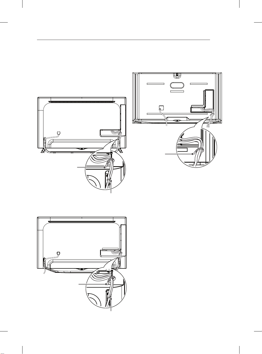
MAKING CONNECTIONS
This section on MAKING CONNECTIONS mainly uses
diagrams for the UB85** models.
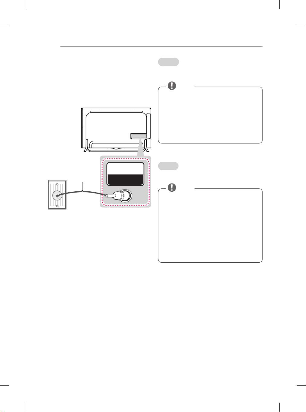
Antenna Connection
Wall Antenna Socket
IN
ANTENNA / CABLE
(*Not Provided)
English
Connect the TV to a wall antenna socket with an RF
cable (75 Ω).
yUse a signal splitter to use more than 2 TVs.
yIf the image quality is poor, install a signal
amplifier properly to improve the image quality.
yIf the image quality is poor with an antenna
connected, try to realign the antenna in the
correct direction.
yAn antenna cable and converter are not supplied.
ySupported DTV Audio: MPEG, Dolby Digital,
Dolby Digital Plus, HE-AAC
NOTE
Italiano
Collegare il televisore all’antenna centralizzata con un
cavo RF (75 Ω).
yUtilizzare uno sdoppiatore del segnale per usare
più di 2 televisori.
ySe la qualità dell’immagine è scarsa, installare
correttamente un amplificatore del segnale per
migliorarla.
ySe la qualità dell’immagine è scarsa con
un’antenna collegata, provare a riallineare
l’antenna nella direzione corretta.
yIl cavo e il convertitore dell’antenna non sono in
dotazione.
yAudio DTV supportato: MPEG, Dolby Digital,
Dolby Digital Plus, HE-AAC
NOTA