10
ENG
English
ASSEMBLING AND PREPARING
Installing the wall mount plate
This monitor has a VESA compatible mount on the
back. Most mounts will require an LG mounting
plate.
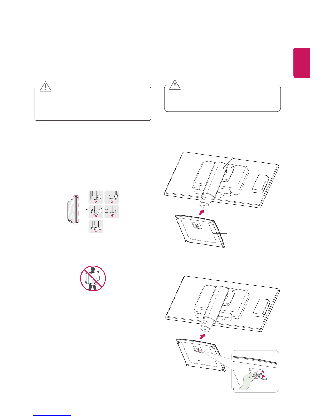
1Place the monitor's screen face down. To
protect the screen from scratches, cover the
surface with a soft cloth.
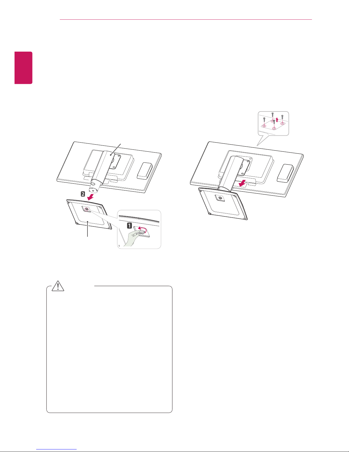
2Place the wall mount plate on the monitor and
align it with the screw holes on the monitor.
3Using a screwdriver, tighten the four screws to
fix the plate onto the monitor.
yThe wall mount plate is sold separately.
yFor more information on the installation, refer
to the wall mount plate's installation guide.
Wall Mount Plate
NOTE
If you intend to mount the Monitor set to a wall,
attach Wall mounting interface (optional parts) to
the back of the set.
When you install the Monitor set using a wall
mounting interface (optional parts), attach it
carefully so it will not drop.
1Please, Use the screw and wall mount interface
in accordance with VESA Standards.
2If you use screw longer than standard, the
monitor might be damaged internally.
3If you use improper screw, the product might be
damaged and drop from mounted position. In
this case, LG Electronics is not responsible for
it.
4VESA compatible.
5Please use VESA standard as below.
y784.8 mm (30.9 inch) and under
* Wall Mount Pad Thickness : 2.6 mm
* Screw : Φ 4.0 mm x Pitch 0.7 mm x
Length 10 mm
y787.4 mm (31.0 inch) and above
* Please use VESA standard wall mount pad
and screws.
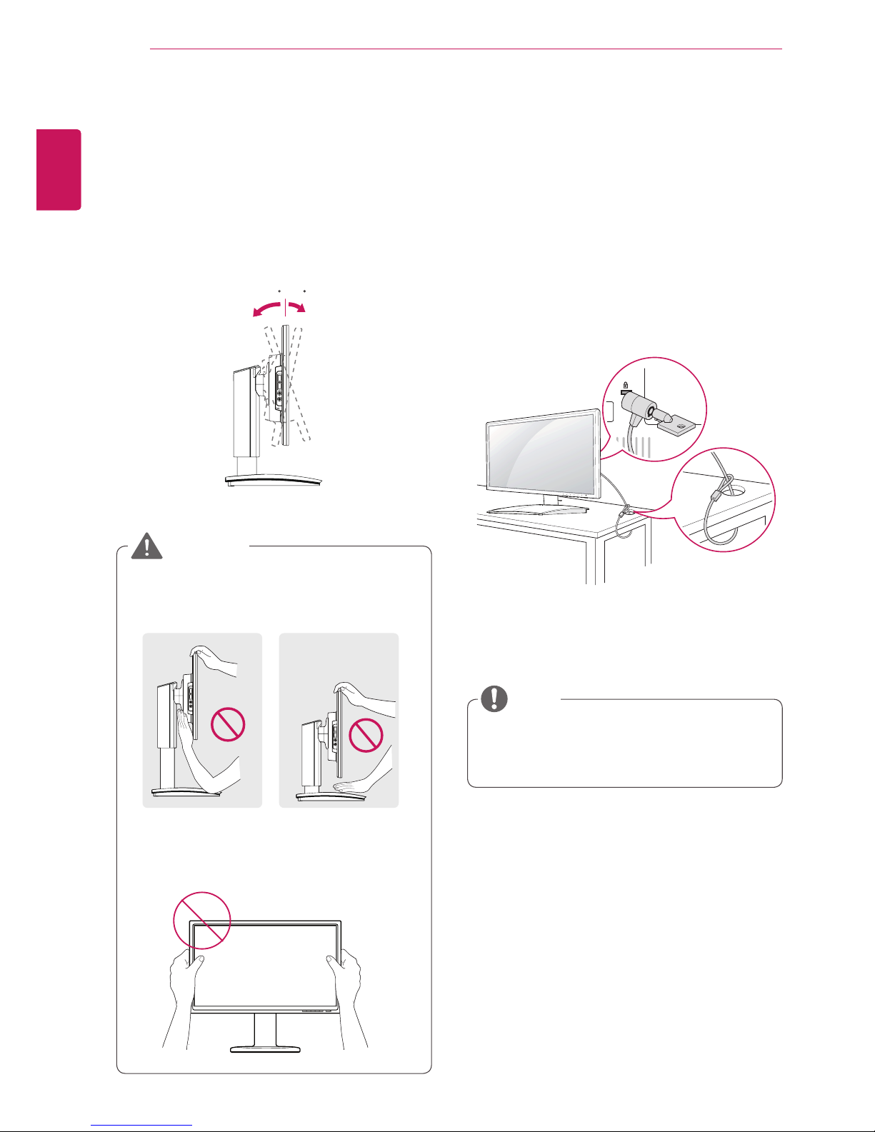
Mounting on a wall
Install the monitor at least 10 cm away from the
wall and leave about 10 cm of space at each side
of the monitor to ensure sufficient ventilation. De-
tailed installation instructions can be obtained from
your local retail store. Please refer to the manual
to install and set up a tilting wall mounting bracket.
10 cm
10 cm
10 cm
10 cm