8
ENG
English
ASSEMBLING AND PREPARING
Detaching the stand body
1Place the monitor's screen face down. To
protect the screen from scratches, cover the
surface with a soft cloth.
2Using a screwdriver, remove the four screws
and detach the stand from the monitor.
yThe components appearing in the illustra-
tions may look different from the actual prod-
uct.
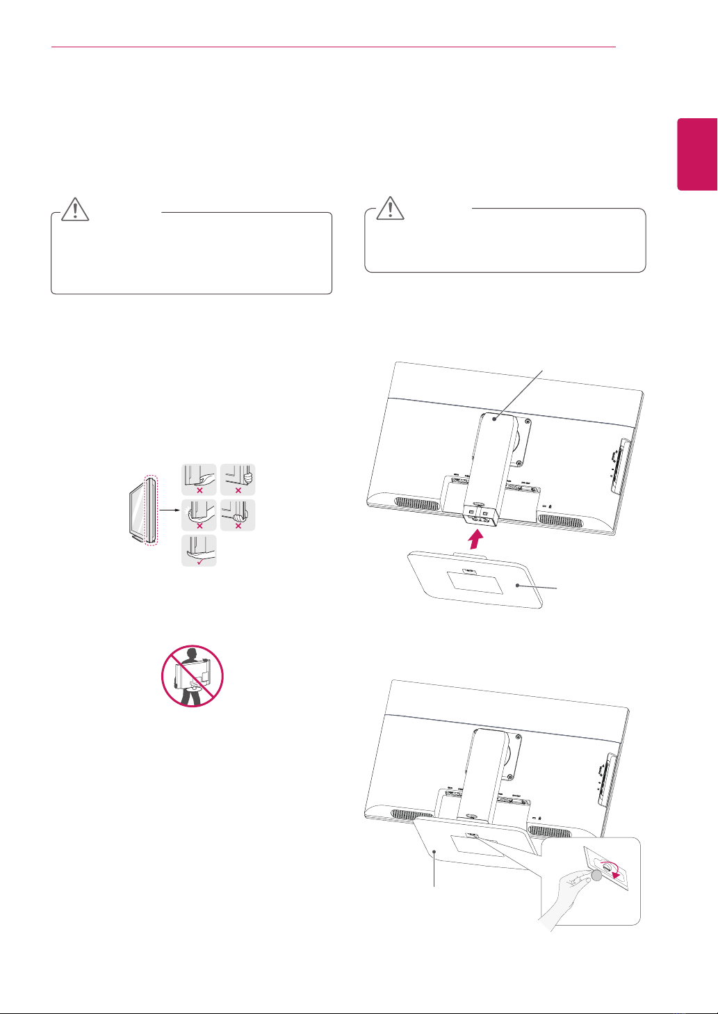
yDo not carry the monitor upside-down as this
may cause it to fall off its stand, resulting in
damage or injury.
yTo avoid damaging the screen when lifting
or moving the monitor, only hold the stand or
the plastic cover. This avoids putting unnec-
essary pressure on the screen.
yOnly remove the tape and the locking pin
when the monitor is mounted on the stand
base and is in an upright position. Otherwise,
the stand body may protrude, which may
lead to injury.
Detaching the stand base
1Place the monitor's screen face down.
To protect the screen from scratches, cover the
surface with a soft cloth.
2Using a coin, turn the screw in the stand base
counterclockwise. Detach the stand base from
the stand body.
CAUTION
Stand Body
Stand Base
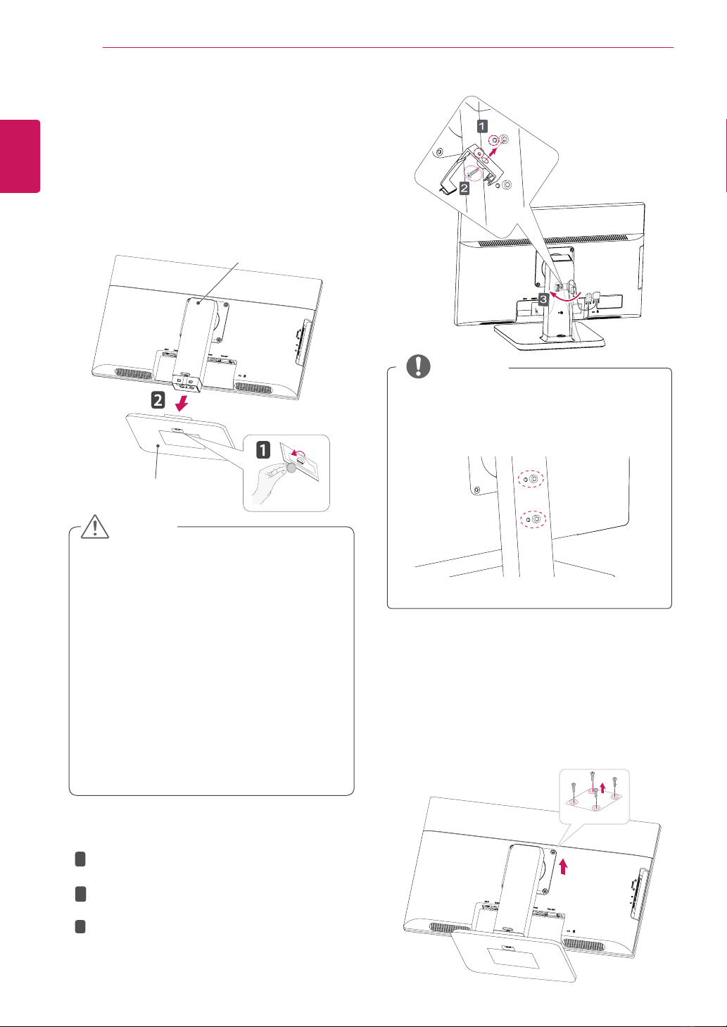
Using the cable holder
NOTE
The holes are used for wall mount bracket.
Varies depending upon your country or
model.
yThe holes are used for wall mount bracket.
yVaries depending upon your country or
model.
NOTE
NOTE
The holes are used for wall mount bracket.
Varies depending upon your country or
model.
Fix the Knob (Cable holder) to the
Hole(Hingebody).
1
2
3
Use one screw to fix the Cable Holder and
monitor set.
Close the Cable holder.