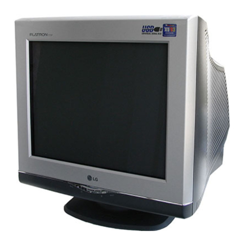
LG Flatron T710B User manual

COLOR MONITOR
SERVICE MANUAL
Website:http://biz.LGservice.com
E-mail:http://www.LGEservice.com/techsup.html
CAUTION
BEFORE SERVICING THE UNIT,
READ THE SAFETY PRECAUTIONS IN THIS MANUAL.
MENU SELECT
MODEL: T710B (T710BJ-AL**E)
CHASSIS NO. : CA-131
( ) **Same model for Service
*Same looking with new chassis.
Issue Date; 2003. 6.

BLOCK DIAGRAM
- 8 -
Input_power
100~240VAC
(50/60Hz)
Line
Filter
Degaussing
Circuit
[ OSD Control ]
Power
Control
(IC901)
TILT
Control
Circuit
6.3V
15V
E2PROM
(IC402)
5V
H-sync Signal
V-sync Signal
I2C DATA(SDA)
I2C CLOCK(SCL)
VIDEO
OSD+pre_Amp
(IC302)
Signal
cable
R
G
BVIDEO
Main_Amp
(IC303)
H/V Sync Processor
( IC701 )
TDA4841 V-out
( IC601)
TDA4867J
H-out
(Q706)
H-Linearity
Correction
Circuit
X-RAY
Protection
Circuit
Dynamic
FOCUS
Circuit
Vertical Blanking,
- 160V
15V
D/D
Feed Back
30V
12V
MICOM
(IC401)
SCL / SDA
H/V sync
PWM control signal 15V
15V
50V
DY CDT
Heater ( 6.3V )
I2C
I2C
I2C
H/V
Sync
Screen
H.V
R/G/B
Bias
R/G/B
Contrast
H-Drive
B-Drive
B+
15V
BRIGHTNESS/CONTRAST
COLOR CURVE
H / V POSITION
H / V SIZE
SPCC
TRAPIZODE
PIN BALANCE
PARALLELOGRAM
TOP CORNER
BOTTOM CORNER
RECALL
DEGAUSSING
MOIRE
LANGUAGE
RESET
OSD TIME
TILT
DPM Control
Circuit
400V
15V
6.3V
15V 80V
Voltage
feedback
Voltage
feedback
Degaussing
Coil
Dynamic Focus
Static Focus
TILT
Coil
50V
80V
15V
G2 G1
DC/DC Converter
FBT
( T701 )
Regulation
Circuit
SMPS
(T901)
5V 15V
CUT-OFF IC
(IC304)
5V
Auto
Beam
Limit

- 11 -
ADJUSTMENT
GENERAL INFORMATION
All adjustment are thoroughly checked and corrected
when the monitor leaves the factory, but sometimes
several adjustments may be required.
Adjustment should be following procedure and after
warming up for a minimum of 30 minutes.
•Alignment appliances and tools.
- IBM compatible PC.
- Programmable Signal Generator.
(eg. VG-819 made by Astrodesign Co.)
- EPROM or EEPROM with saved each mode data.
- Alignment Adaptor and Software.
- Digital Voltmeter.
- White Balance Meter.
- Luminance Meter.
- High-voltage Meter.
AUTOMATIC AND MANUAL DEGAUSSING
The degaussing coil is mounted around the CDT so that
automatic degaussing when turn on the monitor. But a
monitor is moved or faced in a different direction, become
poor color purity cause of CDT magnetized, then press
DEGAUSS on the OSD menu.
ADJUSTMENT PROCEDURE & METHOD
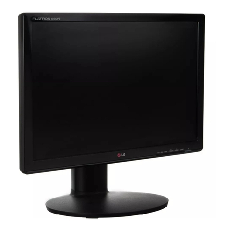
-Install the cable for adjustment such as Figure 1and run
the alignment program on the DOS for IBM compatible PC.
-Set external Brightness and Contrast volume to max position.
1. Checked for B+ Voltage.
1) Display cross hatch pattern at Mode 4.
2) Check D961 voltage to 50.0V ± 1V with.
2. Adjustment for High-Voltage.
1) Display cross hatch pattern at Mode 4.
2) DIST.ADJ→CTRL PWM →High Voltage Command.
3) Adjust High Voltage to 25.8kV
±
0.1 kVdc.
4) Press Enter Key.
3. Adjustment for Factory Mode (Preset Mode).
1) Display cross hatch pattern at Mode 1.
2) Run alignment program for T710BJ on the IBM
compatible PC.
3) EEPROM → ALL CLEAR → Y(Yes) command.
<Caution> Do not run this procedure unless the
EEPROM is changed. All data in EEPROM (mode
data and color data) will be erased.
4) Power button of the monitor turn off →turn on.
5) COMMAND→PRESET START→Y(Yes) command.
6) DIST. ADJ. →CTRL PWM → TILT command.
7) Adjust tilt as arrow keys to be the best condition.
8) DIST. ADJ. →BALANCE command.
9) Adjust parallelogram as arrow keys to be the best
condition.
10)
Adjust balance of pin-balance as arrow keys to be
the best condition.
11)
DIST. ADJ. →FOS. ADJ command.
12)
Adjust V-SIZE as arrow keys to 230
±
2mm.
13)
Adjust V-POSITION as arrow keys to center of the
screen.
14)
Adjust H-SIZE as arrow keys to 310
±
2mm.
15)
Adjust H-POSITION as arrow keys to center of the
screen.
16)
Adjust S-PCC (Side-Pincushion) as arrow keys to be
the best condition.
17)
Adjust TRAPEZOID as arrow keys to be the best
condition.
18)
Save of the Mode 1~4.
19)
Display from Mode 2 to 4 and repeat above from
number 12) to 19)
20)
PRESET EXIT →Y (Yes) command.
4. Adjustment for White Balance and Luminance.
1) Set the White Balance Meter.
2) Press the DEGAUSS on the OSD menu for
demagnetization of the CDT.
3) COLOR ADJ. →LUMINANCE command of the
alignment program.
4) Set Brightness and Contrast to Max position.
5) Display color 0,0 pattern at Mode 4.
6) COLOR ADJ.→BIAS ADJ.→ COLOR No. → 1
command of the alignment program.
7) Check whether green color or not at R-BIAS and G-
BIAS to min position and B-BIAS to 127(7F) position
and Sub-Brightness to 205(CD) position. Adjust G2
(screen) command to 0.4
±
0.05FL of the raster
luminance.
8) Adjust R-BIAS and G-BIAS command to x=0.283
±
0.005 and y=0.298
±
0.005 on the White Balance
Meter with PC arrow keys.
9)
Adjust SUB-Brightnesscommand to 0.4
±
0.1FL of the
raster luminance.
10)
Adjust repeat number 8).
11)
After push the “ENTER”key.
11-1)
COMMAND → PRESET START →Y(Yes) command.
12)
Display color 15,0 full white pattern at Mode 4.
13)
DRIVE ADJ.→ No 1. command.

- 12 -
14)
Set Brightness and Contrast to Max position.
15)
Set SUB-CONTRAST 127(7F) (decimal) position.
16)
Set B-DRIVE to 85(55) at DRIVE of the alignment
program.
17-1)
Adjust R-DRIVE and G-DRIVE command to white
balance x=0.283
±
0.003 and y=0.298
±
0.003 on the
White Balance Meter with PC arrow keys.
17-2)
Display color 15,0 window pattern (70x70mm) at mode 4.
18)
Adjust SUB-CONTRAST command to 50
±
2FL .
19)
After push the “ENTER”key.
20)
Display color 15,0 full white patten at Mode 4..
21)
COLOR ADJ. →LUMINANCE →ABL command.
22)
Adjust ABL to 32
±
1FL of the luminance.
23)
After push the “ENTER”key, and “COMMAND →
PRESET EXIT →Y(Yes)”command.
24)
Exit from the program.
5. Input EDID Data.
1) Display color 15,0 cross hatch pattern at Mode 4.
2) EEPROM → Write EDID command and confirm
“EDID Write OK!!”message of monitor.
3) Exit from the alignment program.
4) Power switch OFF/ON for EDID data save.
6. Adjustment for Focus.
1) Set the Brightness and Contrast to max position.
2) Display H character in full screen at Mode 4.
3) Adjust two Focus control on the FBT that focus
should be the best condition.

- 13 -
TROUBLESHOOTING GUIDE
1. NO POWER
NO POWER
(POWER INDICATOR OFF)
TROUBLE IN
D900
TROUBLE IN FUSE
(F901)
TROUBLE IN
Q901
TROUBLE IN
D941, D942, D951,
D961, D971
TROUBLE IN
Q903, Q952,
Q951, Q942, Q941
CHECK
FUSE OK?
CHECK
C908 VOLTAGE?
(AC120V: 160VDC,
AC220V: 304VDC)
NO
YES
YES
YES
YES
NO
NO
NO
CHECK
IC901 PIN 6
WAVEFORM
?
CHECK
D941, D942,
D951, D961, D971
VOLTAGE?

- 14 -
2. NO CHARACTER
NO CHARACTER
CHECK
IC302
PIN 18(5V) ?
CHECK
IC302 PIN 5, 6, 7?
CHECK
IC302 PIN 19, 20, 21 ?
CHECK
IC303
PIN 1, 2, 3 ?
CHECK
IC303 PIN 4 (80V)
PIN 8 (15V) ?
TROUBLE IN
P302 5V LINE
TROUBLE IN
PC SIGNAL,
P301 SIGNAL CABLE
TROUBLE IN
IC302
TROUBLE IN
P303 15V LINE/
80V LINE
TROUBLE IN IC303
NO
YES
NO
NO
YES
YES
YES
YES
NO
NO
CHECK
R, G, B CATHODE
VOLTAGE?
TROUBLE IN
R331~R333,
L311~L313,
D307~D312
TROUBLE IN
CRT SOCKET
YES
NO

- 15 -
3. NO RASTER
NO VIDEO
(POWER INDICATOR ON)
CHECK
POWER INDICATOR
GREEN or AMBER?
CHECK
D712 ANODE
(-160V)?
CHECK
G1VOLTAGE?
(-55V~-15V)
TROUBLE IN
D712
TROUBLE IN
Q799
DPM MODE
(NO H and/or V SYNC)
AMBER
NO
GREEN
YES
NO
CHECK
CDT HEAT
VOLTAGE? (6.3V)
TROUBLE IN
D941, Q942, Q941
YES
NO
TROUBLE IN
CDT
YES

- 16 -
4. NO HORIZONTAL DEFLECTION
NO H-DEFLECTION
(ONE VERTICAL LINE)
CHECK
Q706?
CHECK
B+ VOLTAGE
(50V)?
CHECK
T701(FBT) PIN 2
(31KHZ 60V,
69KHZ 140V) ?
CHECK
Q705 COLLECTOR
WAVEFORM?
TROUBLE IN
Q706
TROUBLE IN
50V LINE
TROUBLE IN
Q719, Q720, D710
TROUBLE IN
Q705
TROUBLE IN
T701, P701
NO
NO
YES
YES
YES
YES
NO
NO
0V T

- 17 -
5. TROUBLE IN H-LINEARITY
UNBALANCED OF H-LIN.
CHECK
IC401
PIN 6, 7, 8 ?
CHECK
Q711~Q716?
CHECK
L703?
TROUBLE IN
IC401 (MICOM)
TROUBLE IN
Q711 ~ Q716
TROUBLE IN
L703
TROUBLE IN
C722, C723, C726, C729
NO
NO
NO
YES
YES
YES Cs SIGNAL TABLE
HORIZONTAL
FREQUENCY(fH)
30K ~ 33.9K
34K ~ 38.9K
39K ~ 43.9K
44K ~ 48.9K
49K ~ 51.9K
52K ~ 57.9K
58K ~ 61.9K
62K ~ 65.9K
66K ~ 71K
Cs1
L
L
H
H
H
H
H
H
H
Cs3
L
L
L
L
L
L
L
H
H
Cs2
L
H
L
L
H
H
H
H
H

- 18 -
6. NO VERTICAL DEFLECTION
NO V-DEFLECTION
(ONE HORIZONTAL LINE)
CHECK
IC601 PIN 2
(15V+)?
CHECK
IC701 PIN 12, 13?
TROUBLE IN
D951 15V LINE
TROUBLE IN
IC701
TROUBLE IN
IC601, V-CIRCUIT
NO
YES
YES
NO
5V 12Pin
13Pin

- 19 -
7. TROUBLE IN OSD
TROUBLE IN
OSD PERIPHERAL
CIRCUIT
NO OSD
TROUBLE IN
5V LINE
TROUBLE IN
IC401 PIN29 (V-FBP),
IC701 PIN1LINE (H-FBP)
NO
YES
DC 5V
YES
NO
Pin 24 5V
Pin 1
CHECK
IC302 B+
(5V) ?
(ENTER BUTTON MUST BE PRESSED.)
CHECK
IC302 PIN 1, 24
WAVEFORM?

- 20 -
8. TROUBLE IN DPM
CHECK
IC401 (MICOM)
PIN 30, 31 (H/V INPUT)
SIGNAL?
CHECK
IC401 PIN 13
WAVEFORM?
CHECK
IC401 (MICOM)
PIN 2, 3 ?
CHECK
B+LINE
(6.3V,15V+) ?
CHECK PC,
(PC IS NOT GOING INTO
DPM OFF MODE)
TROUBLE IN
X401
TROUBLE IN
IC401 (MICOM)
TROUBLE IN
Q941, Q942, Q951, Q952,
TROUBLE IN PC
OFF MODE FAILURE
INPUT H/V SYNC SIGNAL
H/V SYNC
(NO OFF MODE.)
NO
NO
NO
NO (DPMF: 0V)
DPM TABLE
Mode Item
NORMAL
STAND-BY
SUSPEND
OFF
DPMF
H
L
L
L
LED
GREEN
AMBER
AMBER
AMBER
DPMS
H
H
H
L
YES
YES
SEE DPM TABLE
YES
YES
5V
24MHz

- 21 -
9. NO DEGAUSSING
CHECK
IC401 PIN 5
(0V)?
CHECK
Q953 COLLECTOR
VOLTAGE?
CHECK
P902 ?
CHECK
RL901?
TROUBLE IN
IC401 (MICOM)
TROUBLE IN
Q953
TROUBLE IN
P902
TROUBLE IN
RL901
TROUBLE IN
TH901,
DEGAUSSING COIL
NO DEGAUSSING
DC 15V
NO
NO
NO
NO
YES
YES
YES
YES
(DEGAUSS ON THE OSD MENU MUST BE PRESSED.)

- 22 -
10. NO TILT (NO ROTATION)
NO TILT (NO ROTATION)
TROUBLE IN
IC401 (MICOM)
TROUBLE IN
15V LINE, 6.3V LINE
TROUBLE IN
Q501~Q503
TROUBLE IN
P501, TILT COIL
NO
YES
YES
YES
CHECK
15V LINE
AND 6.3V LINE ?
CHECK
Q503 EMITTER
VOLTAGE ?
NO
NO
CHECK
IC401 PIN21
WAVE FORM ?

- 32 - - 33 -
SCHEMATIC DIAGRAM
Table of contents
Other LG Monitor manuals