LG MT-40PA10 User manual

PDP MONITOR
SERVICE MANUAL
CAUTION
BEFORE SERVICING THE CHASSIS,
READ THE SAFETY PRECAUTIONS IN THIS MANUAL.
CHASSIS : MP-00MB
MODEL : MT/MZ-40PA10/G/S
MODEL : MT/MZ-40PA20/G/S
MODEL : R4018PDP
MODEL : R40PDP28
website:http://biz.LGservice.com
e-mail:http://www.LGEservice.com/techsup.html
Jan.,2002
Printed in KoreaP/NO : 3828VD0070G
All manuals and user guides at all-guides.com
all-guides.com

- 2 -
CONTENTS
Contents ................................................................................................................. 2
Safety Precautions ............................................................................................3
Specifications ..................................................................................................... 4
Control Descriptions ........................................................................................ 5
Adjustment Instructions ............................................................................... 8
Block Diagram .................................................................................................... 12
Wiring Diagram ................................................................................................. 14
Exploded View ............................................................................................ 16,18
Exploded View Parts List ........................................................................17,19
Replacement Parts List ............................................................................... 20
SVC. Sheet ................................................................................................................
All manuals and user guides at all-guides.com

- 3 -
SAFETY PRECAUTIONS
Many electrical and mechanical parts in this chassis have special safety-related characteristics. These parts are identified by in
the Schematic Diagram and Replacement Parts List.
It is essential that these special safety parts should be replaced with the same components as recommended in this manual to
prevent X-RADIATION, Shock, Fire, or other Hazards.
Do not modify the original design without permission of manufacturer.
General Guidance
An lsolation Transformer should always be used during
the servicing of a receiver whose chassis is not isolated from
the AC power line. Use a transformer of adequate power rating
as this protects the technician from accidents resulting in
personal injury from electrical shocks.
It will also protect the receiver and it's components from being
damaged by accidental shorts of the circuitary that may be
inadvertently introduced during the service operation.
If any fuse (or Fusible Resistor) in this monitor is blown, replace
it with the specified.
When replacing a high wattage resistor (Oxide Metal Film
Resistor, over 1W), keep the resistor 10mm away from PCB.
Keep wires away from high voltage or high temperature parts.
Due to high vacuum and large surface area of picture tube,
extreme care should be used in handling the Picture Tube.
Do not lift the Picture tube by it's Neck.
X-RAY Radiation
Leakage Current Cold Check(Antenna Cold Check)
With the instrument AC plug removed from AC source,
connect an electrical jumper across the two AC plug prongs.
Place the AC switch in the on positioin, connect one lead of
ohm-meter to the AC plug prongs tied together and touch other
ohm-meter lead in turn to each exposed metallic parts such as
antenna terminals, phone jacks, etc.
If the exposed metallic part has a return path to the chassis, the
measured resistance should be between 1MΩ and 5.2MΩ.
When the exposed metal has no return path to the chassis the
reading must be infinite.
An other abnormality exists that must be corrected before the
receiver is returned to the customer.
Leakage Current Hot Check (See below Figure)
Plug the AC cord directly into the AC outlet.
Do not use a line Isolation Transformer during this check.
Connect 1.5K/10watt resistor in parallel with a 0.15uF capacitor
between a known good earth ground (Water Pipe, Conduit, etc.)
and the exposed metallic parts.
Measure the AC voltage across the resistor using AC
voltmeter with 1000 ohms/volt or more sensitivity.
Reverse plug the AC cord into the AC outlet and repeat AC
voltage measurements for each esposed metallic part. Any
voltage measured must not exceed 0.75 volt RMS which is
corresponds to 0.5mA.
In case any measurement is out of the limits sepcified, there is
possibility of shock hazard and the set must be checked and
repaired before it is returned to the customer.
Leakage Current Hot Check circuit
1.5 Kohm/10W
To Instrument's
exposed
METALLIC PARTS
Good Earth Ground
such as WATER PIPE,
CONDUIT etc.
AC Volt-meter
IMPORTANT SAFETY NOTICE
0.15uF
All manuals and user guides at all-guides.com

- 4 -
SPECIFICATIONS
Note : Specification and others are subject to change without notice for improvement.
O MONITOR
OVideo receiving system:
PAL
SECAM
NTSC
VGA
SVGA
OInput Voltage : AC 110~240V, 50/60Hz
OPower consumption : Max 330W
Stand-By : 5W
OPDP Module : PDP40NVVDN4
OSpeaker Impedance : 8 ohm
OSound output : 20W max
OFeature : AV Input (Bottom)
Component Input (Bottom)
RGB Input (Bottom,D-Sub 15pin)
External SPK Out (Bottom,SPK Jack)
STB Control Input (Bottom)
STB Audio Input (D-Sub 25pin)
OFuntion : PSM
SSM
Child Lock
Auto Sleep
OExternal Interface
AV/COMPONENT Output
COMPONENT Mode ( Y,Cb/Pb,Cr/Pr)
OSET TOP BOX
OVideo receiving system:
PAL-BG/DK/I
NTSC M
OInput Voltage : AC 110~250V, 50/60Hz
OTuning System : FVS 100 Program
OPower consumption : Max 35W
Stand-By : 5W
OAvailable Channel : VHF : E2~E12(L/L’:B,C,D)
UHF : E21~E69
CATV : S1~S20(HYPER:S21~S41)
OFeature : AV In/out(RCA) : AV1(With RGB in/TV out)
AV In/out(RCA) : AV2(Monitor out)
AV In : AV3(Rear,CVBS)
S-Input : S-Input
Y,Pb,Pr Input : Component(Rear,480I,480P)
RGB Input : RGB-PC(Rear,D-Sub 15pin)
Audio-Input : Component/RGB- PC
RGB out : RGB-PC(Rear,D-Sub 15pin)
RGB out/Control :
PDP MNT connection:RGB,Control
AUDIO out :
PDP MNT connection:L,R(D-Sub 25pin)
Woofer out :
Woofer Speaker
OFuntion : PSM
SSM
Teletext
Auto Sleep
ITEM
AV Video out
AV SYNC out
AV Burst out
AV Audio Out
MIN
0.85
0.25
0.15
0.40
TYP
1.00
0.30
0.30
0.50
MAX
1.15
0.35
0.35
0.60
UNIT
Vpp
Vpp
Vpp
V
PIn Name
R
G
B
GND
H.Sync
V.Sync
STB-DET
SCL
SDA1 out
SDA1 in
SDA2 out
SDA2 in
Spec.
0.7Vpp¡0.05
0.7Vpp¡0.05
0.7Vpp¡0.05
Case Common
4.0Vpp¡0.5
3.0Vpp¡0.5
High/Low
3.0~4.5Vpp
3.0~4.5Vpp
3.0~4.5Vpp
3.0~4.5Vpp
3.0~4.5Vpp
Pin
VSC-Det
GND
GND
GND
GND
GND
GND
GND
GND
GND
GND
GND
No.
13
14
15
16
17
18
19
20
21
22
23
24
REsolution
640*480
640*480
704*480
H-Freq(Khz)
15.73
15.63
31.47
V-Freq(hz)
60
50
59.94
Proposed
SDTV,DVD 480I
SDTV,DVD 480I
SDTV 480P
RGB/HV Control Signal In/Out(D-Sub 25pin Cable)
All manuals and user guides at all-guides.com

- 5 -
CONTROLS DESCRIPTION
ON/OFF
VOLUME
INPUT
SELECT
ON/OFF INPUT VOLUME
SELECT
<Front Panel>
MAIN POWER BUTTON
INPUT SELECT BUTTON
REMOTE CONTROL SENSOR
POWER/STANDBY INDICATOR
Illuminates red in standby
Illuminates green when the Monitor is switched on POWER BUTTON
VOLUME (FF,GG) BUTTON
All manuals and user guides at all-guides.com

- 6 -
PB R
Y P
(+) ( ) (+)( )
AC INPUT
EXTERNAL SPEAKER (8Ω)AV INPUT
RGB-PC INPUT(VGA/SVGA)
R RL L R
AUDIO INPUT RGB INPUT/CONTROL
L
AUDIO
(MONO)
VIDEO
COMPONENT (480i/480p)
(DVD INPUT)
PB
YR
P
(+) ( ) (+)( )
AC INPUT
EXTERNAL SPEAKER (8Ω)
AV INPUT (DVD INPUT)
COMPONENT (480i/480p)
RR
LLR
AUDIO INPUT RGB INPUT/CONTROL
L
AUDIO VIDEO
(MONO)
RGB-PC INPUT(VGA/SVGA)
<Back Panel>
EXTERNAL
SPEAKER (8Ω)
KNOBS
AV INPUT /
COMPONENT (480i/480p)
DVD INPUT SOCKETS
RGB-PC INPUT (VGA/SVGA) /
AUDIO INPUT /
RGB INPUT/CONTROL SOCKETS
POWER INPUT
SOCKET
This Monitor operates
on an AC mains supply,
the voltage is as indicat-
ed as inside back cover
of this manual. Never
apply DC power to the
Monitor.
All manuals and user guides at all-guides.com
all-guides.com

- 7 -
AP-40/42WA20M
(Tilt wall mounting bracket) AP-40/42WA10
(Wall mounting bracket)
MULTIMEDIA
ON/OFF TV/VIDEO MENU ENTER VOL CH
RT/RZ-BA10 (PDP Tuner)
Optional Extras
- Optional extras can be changed or modified for quality improvement without any notification new
optional extras can be added.
- Contract your dealer for buying these items.
AP-40/42CA10 (Ceiling mounting bracket) AP-40/42FA10 (Floor type stand)
AP-40/42DA10 (Desktop stand) AP-40/42SA10 (Speakers)
AP-40/42SA10D
(Speaker stand) AP-40/42SA10F
(Floor type speaker stand)
Video cables Audio cables
All manuals and user guides at all-guides.com

- 8 -
1. Application Object
These instructions are applied to all of the PDP monitor, MP-
00MB.
2. Notes
(1) Because this is not a hot chassis, it is not necessary to use
an isolation transformer. However, the use of isolation
transformer will help protect test instrument.
(2) Adjustment must be done in the correct order.
(3) The adjustment must be performed in the circumstance of
25±5°C of temperature and 65±10% of relative humidity if
there is no specific designation.
(4) The input voltage of the receiver must keep 220/230V,
50/60Hz in adjusting.
(5) The receiver must be operated for about 15 minutes prior
to the adjustment.
¤After receiving 100% white pattern, the receiver must be
operate prior to adjustment.(Or white condition in HEAT-
RUN mode)
¤ŁEnter into HEAT-RUN mode
- Select the HEAT-RUN OFF by pressing ADJ button on
Remote Control for adjustment.
- Press the VOL + button in HEAT-RUN OFF.
(OSD display HEAT-RUN WHITE and screen display
100% full WHITE PATTERN)
¤ØSet is activated HEAT-RUN without SET TOP BOX or
signal generator in this mode.
[Single color pattern of HEAT-RUN mode uses to check
PANEL.(RED/BLUE/GREEN)
[Caution] If you turn on a still screen more than 20 minutes, a
afterinage may be occur in the black level part of the
screen.
3. POWER PCB Assy Voltage Adjustment
[Replace PDP Module or Power Board, adjust certainly Power
PCB Assy Voltage.
3-1. Test Equipment
D.M.M 1EA
3-2. Connection Diagram for Measuring
Refer to Fig 1.
3-3. Adjustment Method
(1) Va Adjusment(Address Voltage Adjusment)
¤Connect pin 1 of P806 or P811 to (+) jack of D.M.M.
¤ŁAfter turning the VR803(Va Adj), voltage of D.M.M
adjustment as same as Va voltage which on label of
panel right/bottom.(Deviation : ±0.5V)
(2) Vs Adjustment
¤Connect pin 9 of P803 to (+) jack of D.M.M.
¤ŁAfter turning the VR804(Vs Adj), voltage of D.M.M
adjust as same as Vs voltage which indicated on label
of panel right/bottom.(Deviation : ±0.5V)
(3) VSC Adjustment
¤Connect pin 4 of P802 to (+) jack of D.M.M.
¤ŁAfter turning the VR806(VSC Adj), voltage of D.M.M
adjust as same as Vs voltage which indicated on label
of panel right/bottom.(Deviation : ±0.5V)
(4) VSETUP Adjustment
¤Connect pin 1 of P802 to (+) jack of D.M.M.
¤ŁAfter turning the VR805(VSETUP Adj),voltage of D.M.M
adjust as same as Vs voltage which indicated on label
of panel right/bottom.(Deviation : ±0.5V)
4. Adjustment of RGB Cut-off and
White Balance
4-1. Required Equipment
Color analyzer(CA-100 or same production)
4-2. Connection Diagram of Equipment for
Measuring
ADJUSTMENT INSTRUCTIONS
VSETUP
VR806
VR805
VR804 DMM
VSC
VAVSC CTL
VA CTL
P814
VR803
GND
VSETUP CTL
VS CTL
VS
<Fig 1> Connection Diagram of Power Adjustment for Measuring
Refer to Typical Voltage
Va
Vs
Vsc
Vsetup
70V
182V
75V
225V
Address Voltage
Sustain Voltage
Scan Voltage
Setuo Voltage
COLOR
ANALYZER
TYPE; CA-100
Window Pattern
CVBS Signal Input
High Light
120±5cd/m2
Low Light
6±1cd/m2 PDP MONITOR
MSPG-2100 or
MSTG-5200
<Fig 2> Connection Diagram of Automatic Adjustment
All manuals and user guides at all-guides.com

- 9 -
4-3. Adjustment of RGB CUT OFF
(1) Select A/C SRT (cut-off automatic adjustment ) by
pressing SVC button on Remote Control for adjustment.
(2) Press the VOL + or VOL - button.
(3) It displayed all of the black on the screen and then
adjustment is started.
(4) If adjustment is finished, exit from adjustment mode by
pressing A/V button.
4-4. Adjustment of White Balance
• White Balance should be done after RGB cut-off become
adjustment.
• Operate the Zero-calibration of the CA—100, then stick
sensor to PDP module surface when you adjust.
(1) Select WHITE PATTERN of HEAT RUN mode by pressing
SVC button on Remote Control for adjustment then
operate HEAT RUN more than 15 minute.
(2) Supply window Signal in pattern generater.
[When adjustment is operated manually, perate process (3)
to (6) regular sequence, when adjustment is operated
automatically perate process (1)~(2).
(3) To adjust Low Light, stick sensor to pattern(Dark), select
the R cut/B cuby pressing SVC button on Remote Control
for adjustment and adjust it until color coordination
becomes X=0.280±0.003, Y=0.310±0.003 and color
temperature becomes 8.800cK ± 500cK by pressing VOL+,
- button. (G-cut fixation)
(4) To adjust High Light, stick sensor to pattern(White).
Select the R Gain/G Gain(adjustment 6) by pressing SVC
button on Remote Control for adjustment and adjust R
Gain/G Gain until color coordination becomes
X=0.280±0.003, Y=0.310±0.003 and color temperature
becomes 8.800cK ± 500cK.(B-Gain fixation)
(5) Confirm the result of the High Light adjustment.
If the deviation of High Light occur, operate the adjustment
of Low Light and High Light again.
(6) Exit adjustment mode using AV button.
5. Color Temperature of STB
White Balance Adjustment
5-1. Required Equipment
Color Analyzer(CA-110, CA-100 or same production)
5-2. Connection diagram of equipment for
measuring
(1) To adjust the deviation of the STB signal output.
(2) Use regular PDP Monitor(JIG).
5-3. Adjustment Method
• Connect the STB to regular PDP Monitor.
• Operate the zero-calibration of the CA-100, then stick
sensor to surface of PDP module when you adjust.
(1) Select ITE PATTERN of HEAT RUN mode by pressing
SVC button on Remote Control for adjustment, then
operate HEAT RUN more than 15 minute.
(Operate the HEAT RUN to adjust the STB at first, then if
OFF hour don’t keep more than 3 minutes, operate next
adjustment of the STB without HEAT RUN.)
(2) Supply window Signal to TD-710 in pattern generator.
[When adjustment is operated manually, perate process (3)
to (7) regular sequence, when adjustment is operated
automatically perate process (1) to (2).
(3) Select STB CXA2101 by pressing SVC,ADJUST button on
Remote Control for adjustment.
(4) To adjust Low Light, stick sensor to 9th pattern(Dark).
Select the B Cut/R Cut, then adjust the B Cut/R Cut until
color coordination becomes X=0.280±0.003,
Y=0.310±0.003 and color temperature becomes 8.800cK ±
500cK by pressing VOL+, - button. (Adjust in B Cut 10±1,
R Cut 6±1)
(5) To adjust High Light, stick sensor to 2th pattern(White).
Select the R Gain/G Gain, then adjust the R Gain/G Gain
until color coordination becomes X=0.280±0.003,
Y=0.310±0.003 and color temperature becomes 8.800cK
±500cK. (B-Gain fixation)
(6) Confirm the result of the High Light adjustment.
If the deviation of High Light occur, operate the adjustment
of Low Light and High Light again.
(Expectation average adjustment data : B-Cut & R-
Cut=6±2, R-Gain/G-Gain=25±3)
(7) Exit adjustment mode using A/V button.
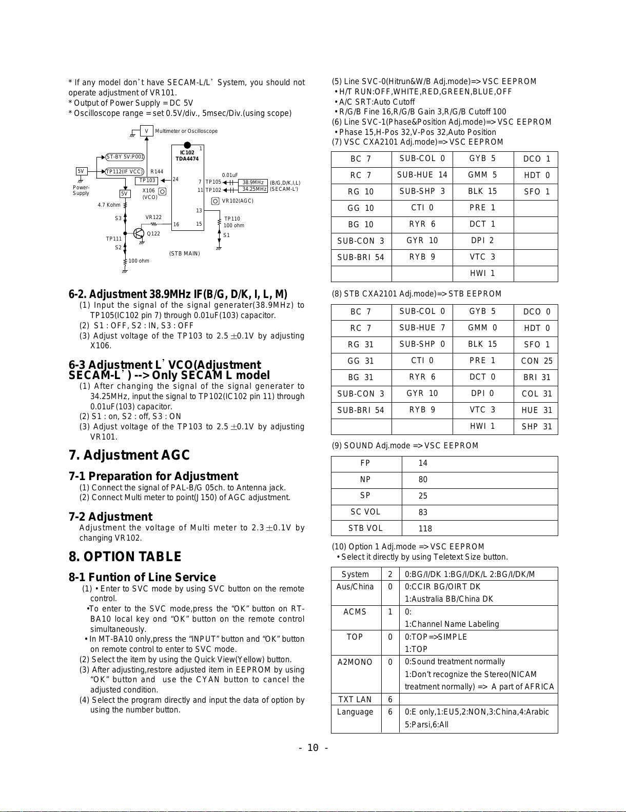
6. Adjustment of VIF-VCO COIL
6-1. Preparation for Adjustment
(1) Connect the equipment for measuring as below.
(2) Setting equipment for measuring.
RF Signal generator
COLOR
ANALYZER
TYPE; CA-100
CVBS Signal Input
PDP MONITOR
RT-BA10(STB)
Window Pattern
MSPG-2100 or MSTG-5200
High Light
120±5cd/m2
Low Light
6±1cd/m2
<Fig 3> Connection Diagram of STB Automatic Adjustment
ADJ.Point
X106
VR101
System
B/G,D/K/I,SECAM-L
SECAM-L’
Frequency
38.9
34.25
Modulation
OFF
OFF
Level
80dBuV
80dBuV
All manuals and user guides at all-guides.com

* If any model don t have SECAM-L/L System, you should not
operate adjustment of VR101.
* Output of Power Supply = DC 5V
* Oscilloscope range = set 0.5V/div., 5msec/Div.(using scope)
6-2. Adjustment 38.9MHz IF(B/G, D/K, I, L, M)
(1) Input the signal of the signal generater(38.9MHz) to
TP105(IC102 pin 7) through 0.01uF(103) capacitor.
(2) S1 : OFF, S2 : IN, S3 : OFF
(3) Adjust voltage of the TP103 to 2.5 0.1V by adjusting
X106.
6-3 Adjustment L VCO(Adjustment
SECAM-L ) --> Only SECAM L model
(1) After changing the signal of the signal generater to
34.25MHz, input the signal to TP102(IC102 pin 11) through
0.01uF(103) capacitor.
(2) S1 : on, S2 : off, S3 : ON
(3) Adjust voltage of the TP103 to 2.5 0.1V by adjusting
VR101.
7. Adjustment AGC
7-1 Preparation for Adjustment
(1) Connect the signal of PAL-B/G 05ch. to Antenna jack.
(2) Connect Multi meter to point(J150) of AGC adjustment.
7-2 Adjustment
Adjustment the voltage of Multi meter to 2.3 0.1V by
changing VR102.
8. OPTION TABLE
8-1 Funtion of Line Service
(1) • Enter to SVC mode by using SVC button on the remote
control.
•To enter to the SVC mode,press the “OK” button on RT-
BA10 local key ond “OK” button on the remote control
simultaneously.
• In MT-BA10 only,press the “INPUT” button and “OK” button
on remote control to enter to SVC mode.
(2) Select the item by using the Quick View(Yellow) button.
(3) After adjusting,restore adjusted item in EEPROM by using
“OK” button and use the CYAN button to cancel the
adjusted condition.
(4) Select the program directly and input the data of option by
using the number button.
(5) Line SVC-0(Hitrun&W/B Adj.mode)=> VSC EEPROM
• H/T RUN:OFF,WHITE,RED,GREEN,BLUE,OFF
• A/C SRT:Auto Cutoff
• R/G/B Fine 16,R/G/B Gain 3,R/G/B Cutoff 100
(6) Line SVC-1(Phase&Position Adj.mode)=> VSC EEPROM
• Phase 15,H-Pos 32,V-Pos 32,Auto Position
(7) VSC CXA2101 Adj.mode)=> VSC EEPROM
(8) STB CXA2101 Adj.mode)=> STB EEPROM
(9) SOUND Adj.mode => VSC EEPROM
(10) Option 1 Adj.mode => VSC EEPROM
• Select it directly by using Teletext Size button.
- 10 -
IC102
TDA4474
TP103
ST-BY 5V:P001
24 7
13
15
1
0.01uF
TP105
X106
(VCO)
5V
Power-
Supply
V Multimeter or Oscilloscope
TP110
38.9MHz
34.25MHz (B/G,D/K,I,L)
(SECAM-L')
100 ohm
S1
5V
4.7 Kohm
S3
Q122
VR122
R144
16
TP112(IF VCC)
S2
TP111
100 ohm
11 TP102
VR102(AGC)
(STB MAIN)
BC 7
RC 7
RG 10
GG 10
BG 10
SUB-CON 3
SUB-BRI 54
SUB-COL 0
SUB-HUE 14
SUB-SHP 3
CTI 0
RYR 6
GYR 10
RYB 9
GYB 5
GMM 5
BLK 15
PRE 1
DCT 1
DPI 2
VTC 3
HWI 1
DCO 1
HDT 0
SFO 1
BC 7
RC 7
RG 31
GG 31
BG 31
SUB-CON 3
SUB-BRI 54
SUB-COL 0
SUB-HUE 7
SUB-SHP 0
CTI 0
RYR 6
GYR 10
RYB 9
GYB 5
GMM 0
BLK 15
PRE 1
DCT 0
DPI 0
VTC 3
HWI 1
DCO 0
HDT 0
SFO 1
CON 25
BRI 31
COL 31
HUE 31
SHP 31
FP
NP
SP
SC VOL
STB VOL
14
80
25
83
118
System
Aus/China
ACMS
TOP
A2MONO
TXT LAN
Language
2
0
1
0
0
6
6
0:BG/I/DK 1:BG/I/DK/L 2:BG/I/DK/M
0:CCIR BG/OIRT DK
1:Australia BB/China DK
0:
1:Channel Name Labeling
0:TOP=>SIMPLE
1:TOP
0:Sound treatment normally
1:Don’t recognize the Stereo(NICAM
treatment normally) => A part of AFRICA
0:E only,1:EU5,2:NON,3:China,4:Arabic
5:Parsi,6:All
All manuals and user guides at all-guides.com

(10) Option 2 Adj.mode
• Select it directly by using Teletext Hold button.
8-2 OSD LANGUAGE
( Select a one among Option in SVC Mode-Language item.)
8-3 TXT LANGUAGE
( Select a one among Option in SVC Mode-TXT LAN item.)
- 11 -
Turbo
I/II save
Woofer
TEXT
Vol Curve
PIP
0
1
0
0
1
0
0:NORMAL Search
1:Turbo Search not use
0:EU
1:NON EU
0:Without Woofer
1:With Woofer
0:Without TEXT
1:With TEXT
0:EU Curve
1:Non EU Curve
0:Without PIP
1:With PIP
0
1
2
3
4
5
6
E Only(English)
EU5(Enlish,German,French,Italian,Spanish)
NON 12
CHINA(English,Chinese)
ARAB(English,French,Arabic,Urdu)
PARSI(English,Parsi)
ALL(Enlish,Norwegian,Czech,German,Danish,Ru
ssian,French,Finish,Chinese,Italian,Portuguess,
Arabic,Spanish,Rumanian,Urdu,Dutch,Polish,
Persian,Swedish,Hungarian)
6
38
40
55
70
128
English,French,SWedish,Czech,German,
Spanish,Italian
Polish,French,SWedish,Czech,German,Spanish,
Italian,English
English(US),French,SWedish,Czech,German,
Spanish,Italian,English(TPU3050 US)
English,French,SWedish,Turkish,German,
Spanish,Italian,English(TPU3050 Turkish)
English(US),Slovakian,Hungarian,Serbian,
Albanian,Polish,Turkish,Rumanian
Polish,Cylrillic,Estonia,Estonia,Estonia,Estonia,
Estonia,Estonia(TPU3051)
128
129
129
130
130
131
131
132
English,French,French,French,French,French,
French,Arabic(TPU3052)
Polish,Cylrillic,SWedish,Czech,Estonia,Estonia,
Estonia,Estonia(TPU3051)
Hebrew,Hebrew,Hebrew,Hebrew,Hebrew,
Hebrew,Hebrew,Arabic(TPU3052)
English,French,SWedish,Turkish,German,
Spanish,Italian,Greek(TPU3051)
English,French,French,Turkish,French,French,
French,Italian(TPU3052)
English,Turkish,Turkish,Turkish,German,Turkish,
Turkish,Greek(TPU3051)
French,French,French,Turkish,French,French,
French,Italian(TPU3052)
English,French,French,French,French,French,
Arabic(TPU3052)
All manuals and user guides at all-guides.com
all-guides.com

- 12 -
BLOCK DIAGRAM
1. VSC Board
Chip for flat panel display application
VGA XGA scale up/down
Triple 8Bit, 80MSPS, 3.3V Video&Graphic Digitizer
with Digital PLL
Analog R/G/B Input to 3X8 Digital R/G/B Output
Display Processor & Scan Rate Converter
(Format Converter)
Interlace to Progressive
15KHz 31KHz(2H X 1V)
Comb Filter Video Process
CVBS(Composite VideoBaseband
Signal) Input to Y/C(Y,U,V) Output
P101
V/R/L
P102
DVD
DS102
DS101
IC203
VPC3230
Decoder
80Pin
3
Y,Cb,Cr
CVBS
(A)
1IC204
SDA9410
Deinterlace&
D/A
100Pin
&
8 LU0-7
8CHR0-7
IC303
Video&Chroma
CXA2101AQ
80Pin
STB-R/G/B/HS/VS(A)
5
PC-R/G/B/HS/VS (A)
5
DTV-Y/Pb/Pr (A)
3TV-Y/U/ V/HS/VS
(A)
5
THS8083
100Pin
IC304
3 CXA-R/G/B(A )
MX88L284
3X2M
Scan converter
208Pin
IC401
IC001
M37270
Micro-Com
IC403
2M
SDRAM
IC402
2M SDRAM
(R/G/B)(D)
CAX-HS/VS
2
16
D0-16
A0-10 D16-31
11 16
OSD_R/G/B/YS
4IC501
74F541
IC502
74F541
IC503
74F541
Buffer
IC504
74F541
OSD_HS/VS
2
HS/VS/Black/Clk
4
8DOR0-7
8DOG0-7
8DOB0-7
STB-POWER
VSC DET/POWER
HDSTB_DET
STB_SCL/SDA
ANA_STB_DET
7PVS/PHS
Black/Clk
4
PAR0-7
8
PAG0-7
8
PAB0-7
8
PD501
(41Pin)
PDP Module
(D)
3X8
Multi-Component Processor
(BasebandVideo Signal Processor)
STB, PC, DTV, TV signals Input to Analog R/G/B Output
D-sub
25
D-sub
15
IC604
LA7222
(Audio S/W)
(A)
P601
L/R
RGB-PC
AV/DVD/COMPONENT IC602
CXA2022S
(Tone Control)
IC603
LA4282
Audio Amp.
(12Wx2) L/R
P007A
(Spk. Jack)
I C
IC203,204,303,304,407
IC002
24C16 IC407
SC786102DW
OSD IC
2 22 L/R
L/R
HS/VS
SDA2
SCL2
LLC1/2
2
VS
PLL HS/
CLK
2
All manuals and user guides at all-guides.com

- 13 -
2. STB Main
TUNER
CXA2069Q
A/V SW
DC 12V
V, L/R
CVBS
(RCA JACK)
V, L/R
* SCART2 : HALF
* RCA Jack
Common Use
*PCBLayOut)
V, L/R
TV, L/R
(SCART1: FULL)
Y / C
AUDIO
COMMON USE
MSP3411G
Sound
Processor
DC 8V
2 nd
SIF
L/R(TV)
L/R
(RCA JACK)
L/R
CVBS1/Y TPU3052S
TELETEXT
DC5V
VPC3230D
MAIN
[ADDR: 47]
Video
Processor
DC 6V
C
DVD Y/Cr/Cb
(A)
VPC3230D
SUB
Processor
DC6V
[ADDR: 44]
Video
SDA9410
1H/1V=> 2H/ 1V
DW / PIP / MPIP
DC 3.3V
L / R OUT
CXA2101AQ
RGB
Processor
DC9V
DTV Y, Pb, Pr (A)
H V
R/G/B/HS/VS(A)
CVBS2/Y
R/G/B
HS/VS(A)
R/G/B
HS/VS(A)
IF IC
TDA4474
DC5V
FB
CVBS.3 RGB
C
EXT_RGB
BA7657F
RGB
S/W
DC 5V
R/G/B
HS/VS(A)
81FIFO
Memory
V04160
RE
WE
RF
SVHS
AV3
AV2
MNT
OUT
DVD/DTV
TV
OUT
AV1
P801
7PIN
Y/ C/HS/VS(D)
M37272
u-COM
IC 001
KEY-1
KIN
KOUT
I2C
SCL-A
SDA-A
I2CSCL-A
SDA-A
I2C
SCL-A
SDA-A
I2CSCL-A
SDA-A
I2CSCL-D
SDA-D
I2CSCL-D
SDA-D
DS 701
(25Pin
Cable)
SCL-A/D
SDA-A/D
9
10
PC- IN
PC- OUT
PC Audio(Stereo)
All manuals and user guides at all-guides.com

- 14 -
WIRING DIAGRAM
P15
P004B
P004A
P14 PD501
P100
P802 P803
P802
P801
P006A
P810
P811
P806
P801
P809
P815
P005A P003A
P304
P007B
P007A
P302
P301
P303
P807 P805
P804
P102
All manuals and user guides at all-guides.com

MEMO
- 15 -
All manuals and user guides at all-guides.com

- 16 -
EXPLODED VIEW (MONITOR)
300
301
303
305
302
200
201 202 203
204
205
206
210
207
209
208
400
401
550
551
530
570
540
520
560
211
212
All manuals and user guides at all-guides.com
all-guides.com

- 17 -
EXPLODED VIEW PARTS LIST
200 6348Q-A002A PDP,40” 4:3 640*480 DOUBLE SCAN
201 6871VSN168A X RIGHT TOP B/D ASSY
202 6871VSN168B X LEFT TOP B/D ASSY
203 6871VSN168C ZCNT TOP B/D ASSY
204 6871VSN168D ZSUS B/D ASSY
205 6871VSN168E ZCNT BOTTOM B/D ASSY
206 6871VSN168F X LEFT BOTTOM B/D ASSY
207 6871VSN168G X RIGHT BOTTOM B/D ASSY
208 6871VSN168H YDRU B/D ASSY
209 6871VSN168J YSUS B/D ASSY
210 6871VSN168K CTRL B/D ASSY
211 4980V00164B SUPPORTER,VERTICAL
212 4980V00164B SUPPORTER,VERTICAL
300 3091V00288C CABINET ASSY LG
3091V00288H CABINET ASSY (SILVER, GREAT WALL)
3091V00288F CABINET ASSY (GOLD)
3091V00A26A CABINET ASSY (40PA20S,LG)
3091V00A26H CABINET ASSY (40PA20S,NO BRAND)
301 4980V00183B SUPPORTER,FILTER(TOP)
302 4980V00180B SUPPORTER,FILTER(BOTTOM )
303 4980V00181B SUPPORTER,FILTER(SIDE)
305 3790V00287A WINDOW FILTER
400 3809V00212C BACK COVER ASSY
3809V00212H BACK COVER ASSY (SILVER, GREAT WALL)
3809V00212F BACK COVER ASSY (GOLD)
401 3301V00005A PLATE ASSY,REAR A/V
3301V00005E PLATE ASSY,REAR A/V (SILVER)
3301V00005D PLATE ASSY,REAR A/V (GOLD)
520 6871VMM704A PWB ASSY,MAIN VSC
530 3501V00028A BOARD ASSY,PDP POWER LINE FILTER
540 6871VSM689A PWB ASSY,CONT
550 6871VSM690A PWB ASSY,PSW
551 5020V00445A BUTTON,POWER
560 6871VSM692A PWB ASSY,AUDIO
570 3501V00027E BOARD ASSY,PDP POWER
No. Part No. Description
All manuals and user guides at all-guides.com

- 18 -
EXPLODED VIEW (SET TOP BOX)
400
174
410
530
300
550
315
320
330
316 311
310
520
540
All manuals and user guides at all-guides.com

- 19 -
EXPLODED VIEW PARTS LIST
174 174-322G POWER CORD VDE 2400MM HOUSING BLAC
300 3110V00101B CASE ASSY,BOTTOM
310 5020V00443A BUTTON,CONTROL 4KEY
311 5020V00448A BUTTON,CONTROL 4KEY
315 3720V00079A PANEL,FRONT
316 3720V00080B PANEL,CONTROL
320 320-062H SPRING,COIL
330 5020V00444B BUTTON,POWER
400 3110V00102A CASE ASSY,TOP
410 3110V00111C CASE ASSY,REAR
520 6871VMM677A PWB ASSY,MAIN RT-BA10(TPU3052)(PH+PH)
6871VMM677B PWB ASSY,MAIN RT-BA10(TPU3050)(PH+PH)
6871VMM677C PWB ASSY,MAIN RT-BA10(TPU3051)(PH+PH)
530 6871VPM062A PWB ASSY,SMPS MP-00MB STB(TD-711)
540 6871VSM658A PWB ASSY,A/V
550 6871VSM718A PWB ASSY,CTL
No. Part No. Description
All manuals and user guides at all-guides.com

- 20 -
REPLACEMENT PARTS LIST(MONITOR)
LOCA. NO PART NO DESCRIPTION
D401
D402
D601
D602
D603
D604
D605
D606
LD001
LED002
LED003
IC006
IC007
Q001
Q001
Q002
Q002
Q020
Q021
Q102
Q103
Q104
Q105
Q106
Q107
Q108
Q109
Q110
Q111
Q201
Q202
Q301
Q302
Q303
Q601
Q603
C001
C002
C003
C008
C011
C016
C022
C026
C038
C045
C105
C107
C109
0DD226239AA
0DD226239AA
0DD226239AA
0DD184009AA
0DD184009AA
0DD184009AA
0DD184009AA
0DD184009AA
0DL200000CA
0DL112100AA
0DL112100AA
0TR830009BA
0TR830009BA
0TR319809AA
0TR387500AA
0TR319809AA
0TR387500AA
0TR387500AA
0TR387500AA
0TR387500AA
0TR387500AA
0TR387500AA
0TR387500AA
0TR387500AA
0TR387500AA
0TR387500AA
0TR387500AA
0TR387500AA
0TR387500AA
0TR150400BA
0TR150400BA
0TR150400BA
0TR150400BA
0TR150400BA
0TR150400BA
0TR150400BA
0CN1040K949
0CE476DD618
0CE108BF618
0CE108BF618
0CE108BF618
0CE108BF618
0CE107DF618
0CE107DF618
0CE107DF618
0CE107DF618
0CE107DF618
0CE107DF618
0CE476DF618
DIODE,SWITCHING CHIP KDS226 SOT-23
DIODE,SWITCHING KDS184S CHIP 85V 300MA KEC TP
DIODE,SWITCHING KDS184S CHIP 85V 300MA
KEC TP
DIODE,SWITCHING KDS184S CHIP 85V 300MA KEC TP
LED,SAM5670(DL-2LRG) BK Y-GREEN -
LED,SR3411(DL-11S2RN1) BK RED -
TR,BSS83 TP PHILIPS NON N-CHANNEL
TR,KTC3198-TP-Y (KTC1815)KEC
TR,CHIP 2SC3875S(ALY) KEC
TR,KTC3198-TP-Y (KTC1815)KEC
TR,CHIP 2SC3875S(ALY) KEC
TR,CHIP 2SA1504S(ASY) KEC
0.1M 50V Z F TA52
47UF STD 10V 20% FL TP 5
1000UF KME 16V M FL TP5
100UF STD 16V M FL TP5
47UF STD 16V M FL TP5
LOCA. NO PART NO DESCRIPTION
IC001
IC002
IC003
IC004
IC005
IC101
IC102
IC201
IC202
IC203
IC204
IC301
IC302
IC303
IC304
IC401
IC402
IC403
IC404
IC406
IC407
IC501
IC502
IC503
IC504
IC601
IC602
IC604
D002
D003
D004
D005
D006
D009
D010
D011
D012
D013
D101
D102
D103
D104
D105
D106
D107
D201
D202
D301
D302
0IZZVA0025A
0IAL241600B
0IFA753307A
0IFA754207A
0IFA754207A
0IPH827150A
0IKE780500D
0ISH323422A
0ISH323422A
0IIT323000D
0ISM941000A
0ISH092100B
0ISH323422A
0ISO210100B
0ITI808300B
0IMR882840B
0IEB121616A
0IEB121616A
0ISH323422A
0ISH323422A
0ICTMMO003A
0IPH745410A
0IPH745410A
0IPH745410A
0IPH745410A
0ISH092100B
0ISO202200A
0ISA722200A
0DD226239AA
0DD226239AA
0DD226239AA
0DD226239AA
0DD226239AA
0DD226239AA
0DD226239AA
0DD226239AA
0DD226239AA
0DD226239AA
0DD226239AA
0DD226239AA
0DD226239AA
0DD226239AA
0DD226239AA
0DD226239AA
0DD226239AA
0DD226239AA
0DD226239AA
0DD226239AA
0DD226239AA
IC,CXP750010 64 BK MT-40PA10 VSC
IC,AT24C16-10PC 8D EEPROM 16K
IC,KA75330ZTA(KA7533ZTA) 3P,TO-92
IC,KA75420ZTA(KA7542ZTA) 3P,TO-92
IC,P82B715T 8SOP R/TP IIC EXTENDE
IC,KIA7805P(KIA78005AP),KEC
IC,PQ3RF23 4P(TO-220) 3.3V REGUL
IC,VPC3230D QA B4 80P QFP TRAY SO
IC,SDA9410 100QFP BK SCAN CONVERT
IC,PQ09RD21 4SIP
IC,PQ3RF23 4P(TO-220) 3.3V REGUL
IC,CXA2101AQ 80P,QFP BK VIDEO SIG
IC,THS8083 100QFP BK ADC IC PD-40
IC,MX88L284-V 208QFP BK SCALE MF0
IC,M12L16161A-7T 50P TSOP ST 16M(
IC,PQ3RF23 4P(TO-220) 3.3V REGUL
IC,SC786107DWR2 MOTOROLA
IC,74F541 20P SOT BK BUFFER MXIC
IC,PQ09RD21 4SIP
IC,CXA2022S 30P SDIP ST TONE CONT
IC,LA7222 (1280 AUDIO)
DIODE,SWITCHING CHIP KDS226 SOT-23
IC
TRANSISTOR
DIODE
CAPACITOR
All manuals and user guides at all-guides.com
This manual suits for next models
13
Table of contents
Other LG Monitor manuals