LG 50PG2 Series User manual

OWNER’S MANUAL
PLASMA TV MODELS
4422PPGG22******
5500PPGG22******
5500PPGG33******
6600PPGG33******
4422PPGG66******
5500PPGG66******
5500PPGG77******
6600PPGG77******
PLASMA TV
Please read this manual carefully before operating
your T .
Retain it for future reference.
Record model number and serial number of the T .
Refer to the label on the back cover and quote this
information.
To your dealer when requiring service.
IIDD NNuummbbeerr((ss))::5495: 60PG30FD-AA
5496: 50PG30FD-AA
5205: 50PG60UD-AA
5206: 42PG60UD-AA
5209: 42PG20D-AA
5210 : 50PG20D-AA
5522: 60PG70FD-AB
5523: 50PG70FD-AB
DVB is a registered trademark
of the DVB Project


1
ACCESSORIES
ACCESSORIES
Ensure that the following accessories are included with your TV. If an accessory is missing, please contact the
dealer where you purchased the product.
Owner’s anual Batteries
Remote Control
Power Cord
Polishing Cloth
Polishing cloth for use on
the screen.
This feature is not available for all models.
* Lightly wipe any stains or fingerprints on the
surface of the TV with the polishing cloth.
Do not use excessive force. This may cause
scratching or discolouration.
RATIO
(only 50PG6***,
50/60PG7*** )
Except 50PG6***, 50/60PG7***
42PG6*** : 1EA
50/60PG3*** : 2EA
42PG2*** : 1EA
50PG2*** : 2EA
(only 50/60PG3***,
42/50PG2***)
Cable management clip
Protection Cover
(only 42/50PG6***,
50/60PG7***)
A
Image shown may differ from your T .
or
Cable Holder
or
Ferrite Core
(only 50/60PG3***,
50/60PG7***)
Ferrite core can be used to reduce the electromagnetic
wave when connecting the power cord.
The closer the location of the ferrite core to the power
plug, the better it is.
se of ferrite core
(only 50/60PG3***, 50/60PG7***)
Install the power plug closely.

2
CONTENTS
CONTENTS
ACCESSORIES
. . . . . . . . . . . . . . . . . . . . . . . . . . . . . . . . . . . . . . . . . . . . .
1
PREPARATION
Front Panel Controls..................................................... 4
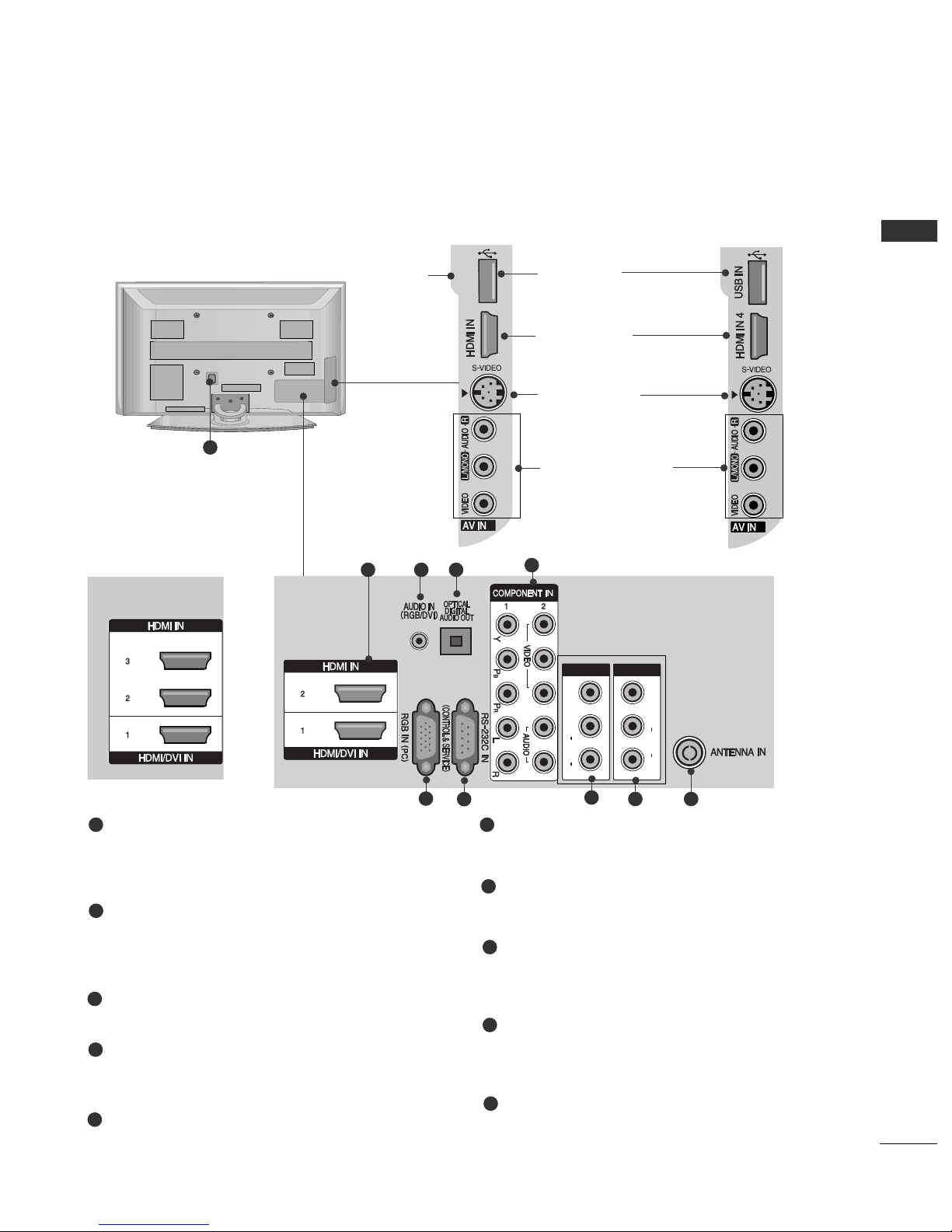
Back Panel Information ................................................ 5
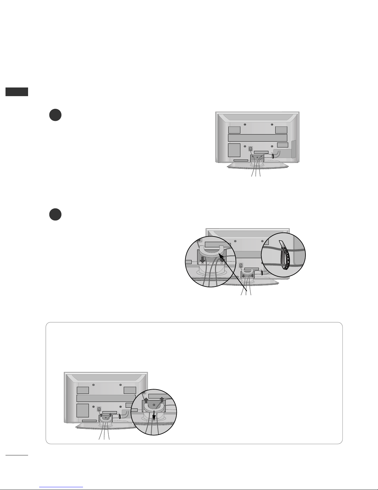
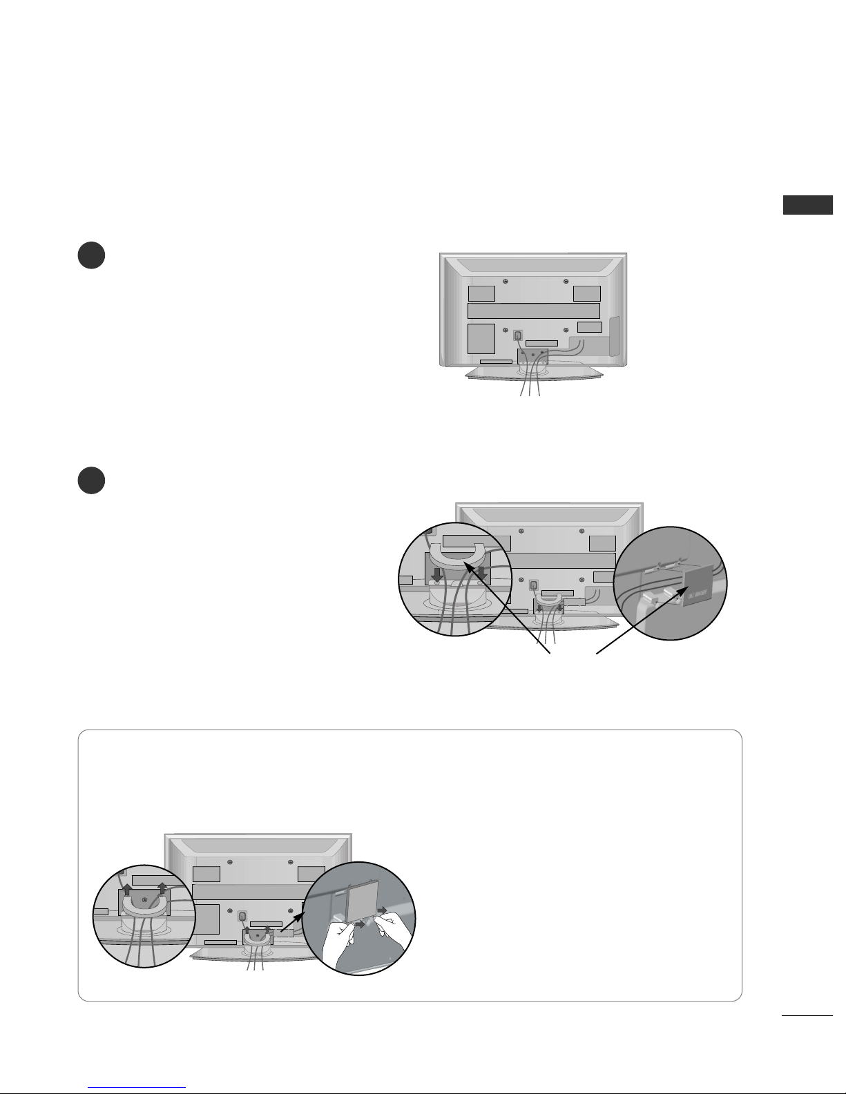
Back Cover for Wire Arrangement ............................ 6
Desktop Pedestal Installation..................................... 9
Swivel Stand ................................................................... 9
Wall Mount: Horizontal Installation........................ 10
Please set it up carefully so the product does not
fall over............................................................................ 11
Antenna Connection................................................... 12
EXTERNAL EQUIP ENT SETUP
HD Receiver Setup...................................................... 13
D D Setup..................................................................... 15
CR Setup ..................................................................... 18
A Output Setup ........................................................ 20
Digital Audio Out Setup............................................ 21
Other A/ Source Setup .......................................... 22
USB in Setup ................................................................ 23
PC Setup........................................................................ 24
- Screen Setup for PC Mode .............................. 27
WATCHING TV / PROGRA E CONTROL
Remote Control Key Functions................................ 32
Turning on the T ....................................................... 36
Programme Selection ................................................ 36
olume Adjustment ................................................... 36
Quick Menu ................................................................. 37
On-Screen Menus Selection and Adjustment..... 38
Auto Programme Tuning............................................ 39
Manual Programme Tuning (In Digital Mode)..... 40
Manual Programme Tuning (In Analogue Mode) ... 41
Programme Edit ........................................................... 43
Booster........................................................................... 46
Software Update.......................................................... 47
Diagnostics ................................................................... 48
Selecting the Programme Table............................... 49
Input List........................................................................ 50
................................................................. 51
Input Label .................................................................... 54
A Mode........................................................................ 55
TO USE THE USB DEVICE
When connecting the USB device.......................... 56
Photo List ...................................................................... 57
Music List........................................................................61
EPG (ELECTRONIC PROGRA E
GUIDE) (IN DIGITAL ODE)
- Switch on/off EPG ............................................... 64
- Select a programme............................................. 64
- Button Function in NOW/NEXT Guide Mode 65
- Button Function in 7 Day Guide Mode.......... 65
- Button Function in Date Change Mode......... 65
-
Button Function in Extended Description Box .
66
-
Button Function in Remind Setting Mode
................. 66
- Button Function in
Remind
List Mode ............. 66
PICTURE CONTROL
Picture Size (Aspect Ratio) Control....................... 67
Preset Picture Settings
- Picture Mode-Preset............................................ 69
- Auto Colour Tone Control
(Cool/Medium/Warm) ........................................ 70
Manual Picture Adjustment
- Picture Mode-User option................................. 71
- Picture Mode-Expert Control ........................... 72
Picture Improvement Technology ........................... 73
Advanced - Film Mode............................................... 74
Advanced - Black(Darkness) Level ......................... 75
Picture Reset................................................................. 76
Image Sticking Minimization (ISM) Method .........77
Power Saving Picture Mode ...................................... 78

3
CONTENTS
SOUND & LANGUAGE CONTROL
Auto olume Leveller.................................................. 79
Preset Sound Settings - Sound Mode................... 80
Sound Setting Adjustment - User Mode .............. 81
Clear oice.................................................................... 82
Balance........................................................................... 83
T Speakers On/ Off Setup......................................84
Selecting Digital Audio Out ..................................... 85
Audio Reset................................................................... 86
Stereo Reception (In Analogue Mode Only) ...... 87
Speaker Sound Output Selection........................... 87
TI E SETTING
Clock Setup .................................................................. 88
Auto On/ Off Timer Setting..................................... 89
Auto Shut-off Setting ................................................. 90
Time Zone Setup......................................................... 91
Sleep Timer Setting..................................................... 91
PARENTAL CONTROL / RATINGS
Set Password & Lock System................................... 92
Block Programme......................................................... 93
Parental Control .......................................................... 94
Key Lock......................................................................... 95
TELETEXT
Switch On/Off ............................................................. 96
SIMPLE Text.................................................................. 96
TOP Text........................................................................ 96
FASTEXT ........................................................................ 97
Special Teletext Functions......................................... 97
APPENDIX
Troubleshooting........................................................... 98
Maintenance ............................................................. 100
Product Specifications............................................. 101
Programming the Remote Control ....................... 102
IR Codes...................................................................... 103
External Control Through RS-232C .................... 105
Open Source Software Notice ............................... 112
Open Source License................................................ 113

4
PREPARATION
PREPARATION
FRONT PANEL CONTROLS
■
Image shown may differ from your T
■
If your T has a protection film attached, remove the film and then wipe the product with a polishing cloth.
OK
MENU
INPUT P
PROGRAMMEVOL MEMEN OKINP T
OKOK
MENUMENU
INPUTINPUT P
OK
MENU
INPUT P
Remote Control Sensor
POWER Button
Power/Standby Indicator
• illuminates red in standby mode.
• illuminates green when the T is
switched on.

5
PREPARATION
BACK PANEL INFORMATION
AV IN 1 AV OUT
L/ MONO
R
AUDIO
VIDEO
L
R
AUDIO
VIDEO
2
Power Cord Socket
This T operates on an AC power. The voltage is
indicated on the Specifications page. Never
attempt to operate the T on DC power.
HDMI Input
Connect a HDMI signal to HDMI IN.
Or D I( IDEO)signal to HDMI/D I port with D I
to HDMI cable.
RGB/DVI Audio Input
Connect the audio from a PC.
OPTICAL DIGITAL A DIO O T
Connect digital audio from various types of equipment.
Note: In standby mode, these ports do not work.
Component Input
Connect a component video/audio device to
these jacks.
RGB Input
Connect the output from a PC.
RS-232C IN (CONTROL & SERVICE) PORT
Connect to the RS-232C port on a PC.
Audio/Video Input (AV IN 1)
Connect audio/video output from an external
device to these jacks.
AV Output
Connect second T or monitor to the A OUT
socket on the set.
Antenna Input
Connect RF antenna to this jack.
1
2
3
4
6
7
8
9
1
A
Image shown may differ from your T .
5
AV IN 1
AV IN 1
AV OUT
AV OUT
L/
L/
MONO
MONO
R
AUDIO
AUDIO
VIDEO
VIDEO
L
R
AUDIO
AUDIO
VIDEO
VIDEO
2
2
USB
SERVICE ONLY
2 3 4 5
10
6789
AV IN 1 AV OUT
L/MONO
R
AUDIO
VIDEO
L
R
AUDIO
VIDEO
2
42/50PG2***
50/60PG3***
42/50PG6***
50/60PG7***
10
AV IN 1 AV OUT
L/MONO
R
AUDIO
VIDEO
L
R
AUDIO
VIDEO
2
2
3
USBUSB
SERVICE ONLYSERVICE ONLY
42/50PG2***
SB Input
(Service
only)
AV IN 1 AV OUT
L/MONO
R
AUDIO
VIDEO
L
R
AUDIO
VIDEO
2
SB Input
HDMI Input
Connect a HDMI signal
to HDMI IN.
S-Video Input
Connect S- ideo out
from an S- IDEO device.
Audio/Video Input
Connect audio/video
output from an external
device to these jacks.
50/60PG3***
42/50PG6***
50/60PG7***
or

6
PREPARATION
PREPARATION
BACK COVER FOR WIRE ARRANGEMENT
■
Image shown may differ from your T .
Connect the cables as necessary.
To connect additional equipment, see the
EEXXTTEERRNNAALL EEQQUUIIPPMMEENNTT SSEETTUUPPsection.
1
Install the CCAABBLLEE MMAANNAAGGEEMMEENNTT CCLLIIPPas shown.
2
Hold the CCAABBLLEE MMAANNAAGGEEMMEENNTT CCLLIIPPwith both hands and pull it upward.
* For the 42PG6*** model, press the center of the CABLE MANAGEMENT CLIP and then lift it.
How to remove the cable management clip
CABLE MANAGEMENT CLIP
Fix the CCaabbllee HHoollddeerr
as shown and bundle
the cables.
42PG6***

7
PREPARATION
Connect the cables as necessary.
To connect additional equipment, see the
EEXXTTEERRNNAALL EEQQUUIIPPMMEENNTT SSEETTUUPPsection.
1
Install the CCAABBLLEE MMAANNAAGGEEMMEENNTT CCLLIIPPas shown.
2
CABLE MANAGEMENT CLIP
50PG6***, 50/60PG7***
Hold the CCAABBLLEE MMAANNAAGGEEMMEENNTT CCLLIIPPwith both hands and pull it upward.
How to remove the cable management clip
Separate CABLE MANAGEMENT from T by
pressing two latches.

8
PREPARATION
PREPARATION
How to remove the cable management clip
■
Image shown may differ from your T .
Connect the cables as necessary.
To connect additional equipment, see the
EXTERNAL EQUIP ENT SETUP section.
Install the CABLE ANAGE ENT CLIP as
shown.
If your T has the CABLE HOLDER, install it
as shown and bundle the cables.
1
2
NOTE
!
GGDo not use the CABLE ANAGE ENT CLIP to lift the T .
- If the T is dropped, you may be injured or the T may be damaged.
Hold the CCAABBLLEE MMAANNAAGGEEMMEENNTT CCLLIIPPwith both hands and pull it upward.
42/50PG2***, 50/60PG3***
CABLE ANAGE ENT CLIP
CABLE HOLDER

9
PREPARATION
OK
MENU
INPUT P
DESKTOP PEDESTAL INSTALLATION
For adequate ventilation allow a clearance of 4” (10cm) all around the TV.
AThe TV can be installed in various ways such as on a wall, or on a desktop etc.
A The TV is designed to be mounted horizontally.
Power Supply
Circuit breaker
EARTHING
Ensure that you connect the earth wire to prevent possible
electric shock. If grounding methods are not possible, have
a qualified electrician install a separate circuit breaker.
Do not try to earth the T by connecting it to telephone
wires, lightening rods or gas pipes.
4 inches
4 inches
4 inches
4 inches
SWIVEL STAND
After installing the TV, you can adjust the TV set manually to the left or right direction by 20 degrees to suit
your viewing position.

10
PREPARATION
PREPARATION
WALL MO NT: HORIZONTAL INSTALLATION
For adequate ventilation allow a clearance of 4” (10cm) all around the TV. We recommend that you use a
wall mounting bracket of LG brand when mounting the TV to a wall.
4 inches
4 inches
4 inches
4 inches
4 inches
NOT SING THE DESK-TYPE STAND
When installing the wall-mounted unit, use the
protection cover for desk-type stand installation.
Insert the PROTECTION COVER into the TV until
clicking sound.
■
Image shown may differ from your T .

11
PREPARATION
PLEASE SET IT P CAREF LLY SO THE PROD CT DOES
NOT FALL OVER.
2
1
AYou should purchase necessary components to fix the TV to the wall on the market.
APosition the TV close to the wall to avoid the possibility of it falling when pushed.
AThe instructions shown below are a safer way to set up the TV, which is to fix it to the wall, avoiding the
possibility of it falling forwards if pulled. This will prevent the TV from falling forward and causing injury.
This will also prevent the TV from damage. Ensure that children do not climb or hang from the TV.
NOTE
!
G When moving the TV undo the cords first.
G se a platform or cabinet strong and large enough to support the size and weight of the TV.
G To use the TV safely make sure that the height of the bracket on the wall and on the TV is the same.
2
3
1
1
2
Use the eye-bolts or T brackets/bolts to fix the product to the wall as shown in the picture.
(If your T has bolts in the eyebolts, loosen then bolts.)
* Insert the eye-bolts or T brackets/bolts and tighten them securely in the upper holes.
Secure the wall brackets with the bolts on the wall. Match the height of the bracket that is mounted on the
wall.
3Use a sturdy rope to tie the product. It is safer to tie the rope so it becomes horizontal between
the wall and the product.

AV IN 1 AV OUT
L/MONO
R
AUDIO
VIDEO
L
R
AUDIO
VIDEO
2
AV IN 1 AV OUT
L/MONO
R
AUDIO
VIDEO
L
R
AUDIO
VIDEO
2
12
PREPARATION
PREPARATION
ANTENNA CONNECTION
AV IN 1 AV OUT
L/ MONO
R
AUDIO
VIDEO
L
R
AUDIO
VIDEO
2
■For optimum picture quality, adjust antenna direction.
■An antenna cable and converter are not supplied.
■To prevent damage do not connect to the mains outlet until all connections are made between the devices.
ulti-family Dwellings/Apartments
(Connect to wall antenna socket)
Single-family Dwellings /Houses
(Connect to wall jack for outdoor antenna)
Outdoor
Antenna
(VHF, HF)
Wall
Antenna
Socket
RF Coaxial Wire (75 ohm)
Antenna
UHF
Signal
Amplifier
VHF
■In poor signal areas, to achieve better picture quality it may be necessary to install a signal amplifier to the
antenna as shown above.
■If signal needs to be split for two T s, use an antenna signal splitter for connection.

13
EXTERNAL EQ IPMENT SET P
HD RECEIVER SET P
■To avoid damaging any equipment, never plug in any power cords until you have finished connecting all equipment.
■This section on EXTERNAL EQ IPMENT SET P mainly uses diagrams for the 42/50PG6*** models.
■
Image shown may differ from your T .
Connecting with a component cables
AV IN 1 AV OUT
L/MONO
R
AUDIO
VIDEO
L
R
AUDIO
VIDEO
1
2
Signal
480i/576i
480p/576p
720p/1080i
108 0 p
Component
Yes
Yes
Yes
Yes
(50Hz/60Hz only)
HDMI
No
Yes
Yes
Yes
(24Hz/30Hz/50Hz/60Hz)
■This T can receive Digital RF/Cable signals without an external digital set-top box. However, if you do receive
Digital signals from a digital set-top box or other digital external device, refer to the diagram as shown below.
Connect the video outputs (Y, PB, PR)of the digital set
top box to the CCOOMMPPOONNEENNTT IINN IIDDEEOOjacks on the
T .
Connect the audio output of the digital set-top box to
the CCOOMMPPOONNEENNTT IINN AAUUDDIIOOjacks on the T .
Turn on the digital set-top box.
(Refer to the owner’s manual for the digital set-top box.)
Select CCoommppoonneenntt 11input source using the IINNPPUUTT
button on the remote control.
If connected to CCOOMMPPOONNEENNTT IINN 22input, select
CCoommppoonneenntt 22 input source.
2
3
4
1

14
EXTERNAL EQ IPMENT SET P
Connecting a set-top box with an HD I cable
AV IN 1 AV OUT
L/MONO
R
AUDIO
VIDEO
L
R
AUDIO
VIDEO
1
Connecting with an HD I to DVI cable
AVV IN 1 AV OUT
L/L/MONOMONO
R
AUDIOAUDIO
VIDEOVIDEO
L
R
AUDIO
VIDEO
12
Connect the digital set-top box to HHDDMMII//DDII IINN 11,
HHDDMMII IINN 22,HHDDMMII IINN 33 or HHDDMMII IINN 44(except
42/50PG2***) jack on the T .
Turn on the digital set-top box.
(Refer to the owner’s manual for the digital set-top box.)
Select HHDDMMII11, HHDDMMII22, HHDDMMII33 or HHDDMMII44(except
42/50PG2***) input source using the IINNPPUUTTbutton
on the remote control.
2
3
1
Connect the digital set-top box to HHDDMMII//DDII IINN 11
jack on the T .
Connect the audio output of the digital set-top box to
the AAUUDDIIOO IINN ((RRGGBB//DDII)) jack on the T .
Turn on the digital set-top box. (Refer to the owner’s
manual for the digital set-top box.)
Select HHDDMMII11input source using the IINNPPUUTTbutton
on the remote control.
2
3
4
1

15
EXTERNAL EQ IPMENT SET P
DVD SET P
Connecting with a component cables
2
Component Input ports
To achieve better picture quality, connect a DVD player to the component input ports as shown below.
Component ports on the T
YP
BPR
ideo output ports
on D D player
Y
Y
Y
Y
PB
B-Y
Cb
Pb
PR
R-Y
Cr
Pr
1
2
Connect the video outputs (Y, PB, PR)of the D D to the
CCOOMMPPOONNEENNTT IINN IIDDEEOOjacks on the T .
Connect the audio outputs of the D D to the
CCOOMMPPOONNEENNTT IINN AAUUDDIIOOjacks on the T .
Turn on the D D player, insert a D D.
Select CCoommppoonneenntt 11input source using the IINNPPUUTT
button on the remote control.
If connected to CCOOMMPPOONNEENNTT IINN 22input, select
CCoommppoonneenntt 22 input source.
Refer to the D D player's manual for operating
instructions.
2
3
4
5
1

16
EXTERNAL EQ IPMENT SET P
Connecting with a S-Video cable
L R
S-VIDEOVIDEO
OUTPUT
SWITCH
ANT IN
ANT OUT
2
Connect the S- IDEO output of the D D to the SS--
IIDDEEOOinput on the T .
Connect the audio outputs of the D D to the AAUUDDIIOO
input jacks on the T .
Turn on the D D player, insert a D D.
Select AA22input source using the IINNPPUUTTbutton on
the remote control.
Refer to the D D player's manual for operating
instructions.
2
3
4
5
1
12

17
EXTERNAL EQ IPMENT SET P
2
Connecting the HD I cable
Connect the HDMI output of the D D to the
HHDDMMII//DDII IINN 11,HHDDMMII IINN 22,HHDDMMII IINN 33 or HHDDMMII
IINN 44(except 42/50PG2***) jack on the T .
Select HHDDMMII11, HHDDMMII22, HHDDMMII33 or HHDDMMII44(except
42/50PG2***) input source using the IINNPPUUTTbutton
on the remote control.
Refer to the D D player's manual for operating
instructions.
2
3
1
1
GGThe T can receive video and audio signals simultaneously
when using a HDMI cable.
GGIf the D D does not support Auto HDMI, you must set the
output resolution appropriately.
NOTE
!

VCR SET P
■To avoid picture noise (interference), allow adequate distance between the VCR and TV.
■Typically a frozen still picture from a VCR. If 4:3 picture format is used for an extended period the fixed
images on the sides of the screen may remain visible.
AV IN 1 AV OUT
L/MONO
R
AUDIO
VIDEO
L
R
AUDIO
VIDEO
AV IN 1 AV OUT
L/MONO
R
AUDIOAUDIO
VIDEO
L
R
AUDIOAUDIO
VIDEO
OUTPUT
SWITCH
ANT IN
R
S-VIDEO VIDEO
ANT OUT L
2
2
Wall Jack
Antenna
1
2
Connecting with a RF Cable
18
EXTERNAL EQ IPMENT SET P
Connect the AANNTT OOUUTTsocket of the CR to the AANNTTEENNNNAA IINNsocket on the T .
Connect the antenna cable to the AANNTT IINNsocket of the CR.
Press the PPLLAAYYbutton on the CR and match the appropriate channel between the T and CR for
viewing.
2
3
1
This manual suits for next models
15
Table of contents
Other LG Plasma TV manuals
Popular Plasma TV manuals by other brands

Panasonic
Panasonic Viera TC-P42G25 Manual de instrucciones

Panasonic
Panasonic Viera TH-50PX75U operating instructions

Samsung
Samsung PS42B430 user manual

Panasonic
Panasonic TH-P58S20M Service manual

Panasonic
Panasonic TH42PZ85UA - 42" PLASMA TV Manual de instrucciones

Panasonic
Panasonic Viera TX-P42U20E operating instructions