LG 50PX5R User manual

PLASMA TV
OWNER’S MANUAL
Please read this manual carefully and completely before
operating your TV.
Retain this manual for future reference.
Record model number and serial number of the TV in the
spaces provided below.
See the label attached on the back cover and relate this
information to your dealer if you require service.
Model Number :
Serial Number :
MODELS: 42PX4RV/50PX5R
42PX4RV-UC/ 42PX4RV-MC/ 50PX5R-UC

2 Plasma TV
Warning/Caution
WARNING/CAUTION:
TO REDUCE THE RISK OF ELECTRIC SHOCK DO NOT REMOVE COVER (OR BACK). NO USER
SERVICEABLE PARTS INSIDE. REFER TO QUALIFIED SERVICE PERSONNEL.
The lightning flash with arrowhead symbol, within an equilateral triangle, is intended to alert the user to
the presence of uninsulated “dangerous voltage” within the product’s enclosure that may be of suffi-
cient magnitude to constitute a risk of electric shock to persons.
The exclamation point within an equilateral triangle is intended to alert the user to the presence of
important operating and maintenance (servicing) instructions in the literature accompanying the appli-
ance.
WARNING/CAUTION:
TO PREVENT FIRE OR SHOCK HAZARDS, DO NOT EXPOSE THIS PRODUCT TO RAIN OR MOISTURE.
FCC NOTICE
• A Class B digital device
This equipment has been tested and found to comply with the limits for a Class B digital device, pursuant to Part
15 of the FCC Rules. These limits are designed to provide reasonable protection against harmful interference in
a residential installation. This equipment generates, uses and can radiate radio frequency energy and, if not
installed and used in accordance with the instructions, may cause harmful interference to radio communications.
However, there is no guarantee that interference will not occur in a particular installation. If this equipment does
cause harmful interference to radio or television reception, which can be determined by turning the equipment off
and on, the user is encouraged to try to correct the interference by one or more of the following measures:
- Reorient or relocate the receiving antenna.
- Increase the separation between the equipment and receiver.
- Connect the equipment into an outlet on a circuit different from that to which the receiver is connected.
- Consult the dealer or an experienced radio/TV technician for help.
• Any changes or modifications not expressly approved by the party responsible for compli-
ance could void the user’s authority to operate the equipment.
CAUTION:
Do not attempt to modify this product in any way without written authorization from LG Electronics. Unauthorized mod-
ification could void the user’s authority to operate this product.
COMPLIANCE:
The responsible party for this product’s compliance is:
LG Electronics U.S.A., Inc
1000 Sylvan Avenue, Englewood Cliffs, NJ 07632
1-800-243-0000
http://www.lgusa.com
WARNING
RISK OF ELECTRIC SHOCK
DO NOT OPEN
/CAUTION
WARNING/CAUTION
TO REDUCE THE RISK OF FIRE AND ELECTRIC SHOCK, DO NOT EXPOSE THIS PRODUCT TO
RAIN OR MOISTURE.
W
Warning/Caution
arning/Caution

Owner’s Manual 3
Safety Instructions
IMPORTANT SAFETY INSTRUCTIONS
Important safety instructions shall be provided with each apparatus. This information shall be given in a separate booklet
or sheet, or be located before any operating instructions in an instruction for installation for use and supplied with the appa-
ratus.
This information shall be given in a language acceptable to the country where the apparatus is intended to be used.
The important safety instructions shall be entitled “Important Safety Instructions”. The following safety instructions shall be
included where applicable, and, when used, shall be verbatim as follows. Additional safety information may be included by
adding statements after the end of the following safety instruction list. At the manufacturer’s option, a picture or drawing that
illustrates the intent of a specific safety instruction may be placed immediately adjacent to that safety instruction :
1. Read these instructions.
2. Keep these instructions.
3. Heed all warnings.
4. Follow all instructions.
5. Do not use this apparatus near water.
6. Clean only with dry cloth.
7. Do not block any ventilation openings. Install in accordance with the manufacturer’s instructions.
8. Do not install near any heat sources such as radiators, heat registers, stoves, or other apparatus (including ampli-
fiers)that produce heat.
9. Do not defeat the safety purpose of the polarized or grounding-type plug. A polarized plug has two blades with
one wider than the other. A grounding type plug has two blades and a third grounding prong, The wide blade or the
third prong are provided for your safety. If the provided plug does not fit into your outlet, consult an electrician for
replacement of the obsolete outlet.
10. Protect the power cord from being walked on or pinched particularly at plugs, convenience receptacles, and the
point where they exit from the apparatus.
11. Only use attachments/accessories specified by the manufacturer.
12. Use only with the cart, stand, tripod, bracket, or table specified by the manufacturer, or sold with the apparatus.
When a cart is used, use caution when moving the cart/apparatus combination to avoid injury from tip-over.
PORTABLE CART WARNING
Safety Instructions
Safety Instructions

4 Plasma TV
Safety Instructions
Contents
Contents
After reading this manual, keep it handy for future reference.
Safety Instructions . . . . . . . . . . . . . . . . . . . . . . . . . . . . .2~3
Introduction
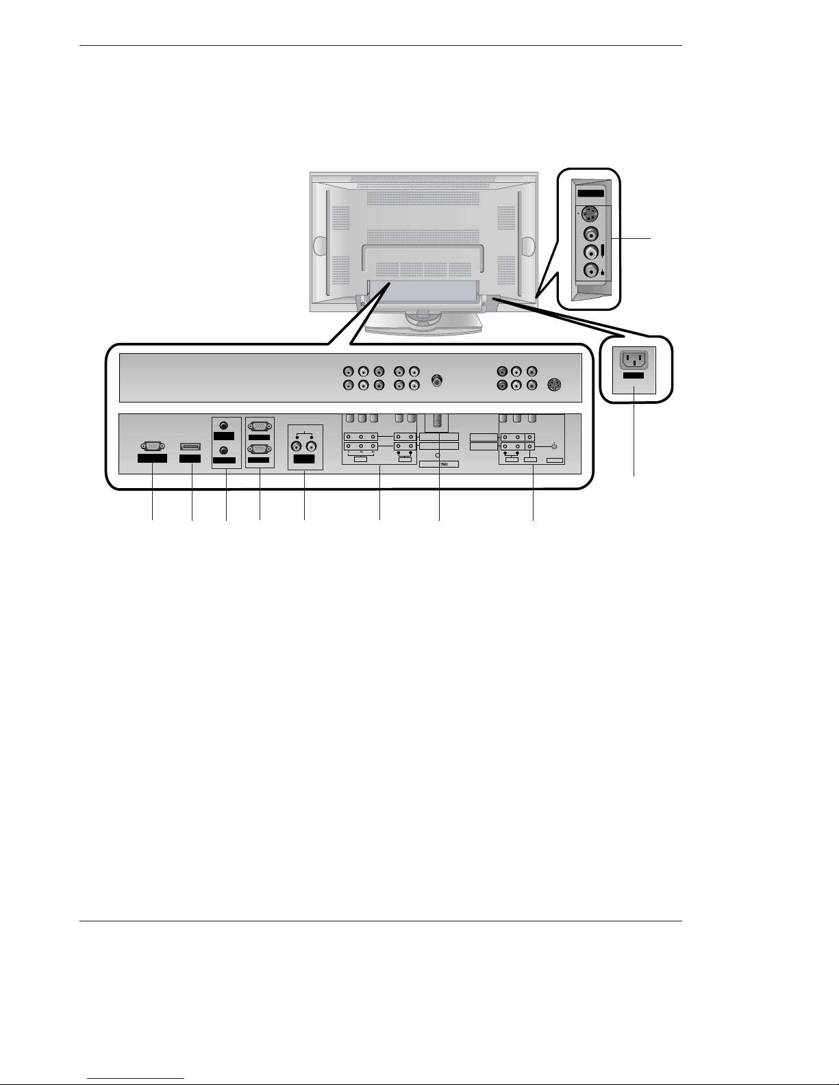
Controls . . . . . . . . . . . . . . . . . . . . . . . . . . . . . . .6
Connection Options . . . . . . . . . . . . . . . . . . . . . .7
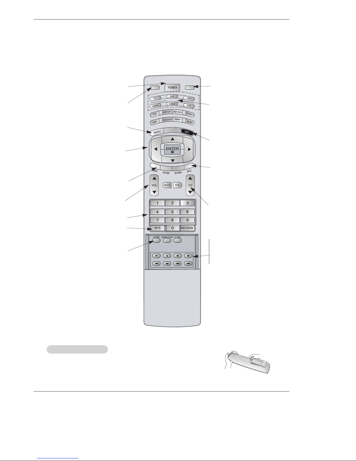
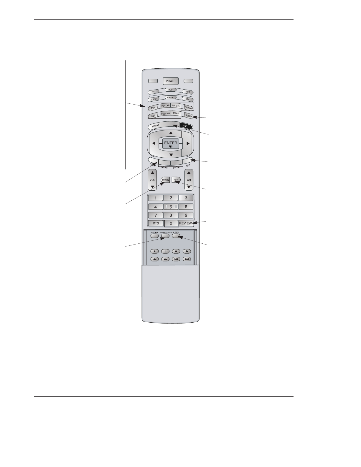
Remote Control Key Functions . . . . . . . . . . . .8~9
Installation
HDMI . . . . . . . . . . . . . . . . . . . . . . . . . . . . . . .10~11
Installation Instruction . . . . . . . . . . . . . . . . . . .12~13
Installation Options . . . . . . . . . . . . . . . . . . . . . . . .14
External Equipment Connections . . . . . . . . . .15~20
Antenna Connection . . . . . . . . . . . . . . . . . . . . .15
VCR Setup / Cable TV Setup . . . . . . . . . . . . . .16
External A/V Source Setup . . . . . . . . . . . . . . . .17
DVD Setup . . . . . . . . . . . . . . . . . . . . . . . . . . . .17
DTV Setup / Monitor Out Setup . . . . . . . . . . . . .18
PC Setup . . . . . . . . . . . . . . . . . . . . . . . . . .19~20
Operation
Turning the TV On . . . . . . . . . . . . . . . . . . . . . . . .21
Menu Language Selection . . . . . . . . . . . . . . . . . .21
Channel Menu Options
Auto Program: Channel Search . . . . . . . . . . . . .22
Manual Program: Adding/Deleting Channels . . .22
Fine Tuning Adjustment . . . . . . . . . . . . . . . . . .22
Signal Reception Booster . . . . . . . . . . . . . . . . .23
Favorite Channels Setup . . . . . . . . . . . . . . . . . .23
Picture Menu Options
APC (Auto Picture Control) . . . . . . . . . . . . . . . .24
Color Temperature Control . . . . . . . . . . . . . . . .24
XD . . . . . . . . . . . . . . . . . . . . . . . . . . . . . . . . . .24
ACM . . . . . . . . . . . . . . . . . . . . . . . . . . . . . . . . .25
sRGB . . . . . . . . . . . . . . . . . . . . . . . . . . . . . . . .25
Manual Picture Control(User option) . . . . . . . . .25
Sound Menu Options
DASP (Digital Auto Sound Processing) . . . . . . .26
BBE . . . . . . . . . . . . . . . . . . . . . . . . . . . . . . . . .26
AVL (Auto Volume Leveler) . . . . . . . . . . . . . . . .26
Manual Sound Control (User option) . . . . . . . . .27
TV speaker Setup . . . . . . . . . . . . . . . . . . . . . . .27
Stereo/SAP Broadcasts Setup . . . . . . . . . . . . .27
Timer Menu Options
Clock Setup . . . . . . . . . . . . . . . . . . . . . . . . . . .28
On/Off Timer Setup . . . . . . . . . . . . . . . . . . . . .28
Auto Off / Sleep Timer . . . . . . . . . . . . . . . . . . .28
Special Menu Options
Key Lock . . . . . . . . . . . . . . . . . . . . . . . . . . . . .29
ISM (Image Sticking Minimization) Method . . . .29
Low Power . . . . . . . . . . . . . . . . . . . . . . . . . . . .30
XD Demo . . . . . . . . . . . . . . . . . . . . . . . . . . . . .30
Closed Captions . . . . . . . . . . . . . . . . . . . . . . . .31
Caption/Text . . . . . . . . . . . . . . . . . . . . . . . . . . .31
Screen Menu Options
Auto Adjustment . . . . . . . . . . . . . . . . . . . . . . .32
Setting Picture Format . . . . . . . . . . . . . . . . . . .32
Manual Configure . . . . . . . . . . . . . . . . . . . . . .32
Selecting VGA Mode . . . . . . . . . . . . . . . . . . . . .32
Screen Position . . . . . . . . . . . . . . . . . . . . . . . .33
Cinema Mode Setup . . . . . . . . . . . . . . . . . . . . .33
NR(Noise Reduction) . . . . . . . . . . . . . . . . . . . .33
Initializing (Reset to original factory value) . . . . .33
PIP (Picture-In-Picture)/Double Window Feature
Watching PIP/Double Window . . . . . . . . . . . . ..34
Swapping the PIP/Double Window . . . . . . . . . .34
TV Program selection for PIP . . . . . . . . . . . . . .34
Selecting an Input Signal Source for PIP/Double Window .
34
Moving the PIP(PIP Mode only) . . . . . . . . . . . .34
PIP Size . . . . . . . . . . . . . . . . . . . . . . . . . . . . . .34
PIP Transparency (PIP Mode only) . . . . . . . . . .34
External Control Device Setup . . . . . . . . . . . . . . . .35~41
IR Codes . . . . . . . . . . . . . . . . . . . . . . . . . . . . . . . .42~43
Programming the Remote . . . . . . . . . . . . . . . . . . . . . .44
Programming Codes . . . . . . . . . . . . . . . . . . . . . . .44~45
Troubleshooting Checklist . . . . . . . . . . . . . . . . . . . . . .46
Product Specifications . . . . . . . . . . . . . . . . . . . . . . . . .47

Owner’s Manual 5
Introduction
Introduction
Introduction
What is a Plasma Display Panel (PDP)?
A plasma display panel is the latest display technology and the best way to achieve flat panel displays with excellent image quality
and large screen sizes that are easily viewable. The PDP can be thought of as a descendant of the neon lamp and it can be also
be viewed as a series of fluorescent lamps.
How does it work?
PDP is an array of cells, known as pixels, which are comprised of 3 sub pixels, corresponding to the colors red, green, and blue.
Gas in a plasma state is used to react with phosphors in each sub-pixel to produce colored light (red, green, or blue). These phos-
phors are the same types used in Cathode Ray Tube (CRT) devices such as televisions and common computer monitors.
You get the rich, dynamic colors that you expect. Each sub-pixel is individually controlled by advanced electronics to produce over
16 million different colors. All of this means that you get perfect images that are easily viewable in a display that is less than 5
inches thick.
160° - Wide angle range of vision
Your flat panel plasma screen offers an exceptionally broad viewing angle -- over 160 degrees. This means that the display is
clear and visible to viewers anywhere in the room who can see the screen.
Wide Screen
The screen of the Plasma Display is so wide that your viewing experience is as if you are in a theater.
Multimedia
Connect your plasma display to a PC and you can use it for conferencing, games, and Internet browsing. The Picture-in-Picture
feature allows you to view your PC and video images simultaneously.
Versatile
The light weight and thin size makes it easy to install your plasma display in a variety of locations where conventional TVs will not
fit.
The PDP Manufacturing Process: a few minute colored dots may be present on the PDP screen
The PDP (Plasma Display Panel), which is the display device of this product is composed of 0.9 to 2.2 million cells. A few cell
defects will normally occur in the PDP manufacturing process. Several tiny, minute colored dots visible on the screen should be
acceptable. This also occurs in other PDP manufacturers' products. The tiny dots appearing does not mean that this PDP is defec-
tive. Thus a few cell defects are not sufficient cause for the PDP to be exchanged or returned. Our production technology mini-
mizes these cell defects during the manufacture and operation of this product.
Cooling Fan Noise (50PX5R only)
In the same way that a fan is used in a PC computer to keep the CPU (Central Processing Unit) cool, the PDP is equipped with
cooling fans to cool the Monitor and improve its reliability. Therefore, a certain level of noise could occur while the fans are operat-
ing and cooling the PDP.
The fan noise doesn't have any negative effect on the PDP's efficiency or reliability. The noise from these fans is normal during the
operation of this product. We hope you understand that a certain level of noise from the cooling fans is acceptable and is not suffi-
cient cause for the PDP to be exchanged or returned.

6 Plasma TV
Introduction
Controls
Controls
- This is a simplified representation of front panel.
Here shown may be somewhat different from your TV.
- This manual explains the features available on the 42PX4RV series TVs.
Front Panel Controls
PR
VOL
MENUTV/AV
OK
CH
VOL
MENUTV/VIDEO ENTER
21 3 4 5 6
7
8
1. Power Button
Switches the set on from standby or off to standby.
2. Remote Control Sensor
3. TV/VIDEO Button
Selects the TV, VIDEO, Component, RGB or HDMI modes.
Switches the set on from standby.
4. MENU
Displays on screen menus one by one.
Exits the current menu.
Memorizes menu changes.
5. ENTER
Accepts your selection or displays the current mode.
6. DD/ EE(Programme Up/Down)
Selects a programme or a menu item.
Switches the set on from standby.
FF/ GG(Volume Up/Down)
Adjusts the volume.
Adjusts menu settings.
7. Power Indicator
Illuminates red in standby mode, Illuminates green when the
set is turned on.
8. Intelligent Eye
Adjusts picture according to the surrounding conditions.

Owner’s Manual 7
Introduction
Connection Options
Connection Options
S-VIDEO
VIDEOAUDIOR
L/MONO
A/V INPUT2A/V INPUT2
AC INPUT
RS-232C INPUT
(CONTROL/SERVICE)
AUDIO
LR
REMOTE
CONTROL
AUDIO INPUT
RGB INPUT
VARIABLEARIABLE
AUDIO OUTAUDIO OUT
HDMI/
DVI(VIDEO)
RGB OUTPUT
Antenna
S-VIDEO
COMPONENT INPUT 2
COMPONENT INPUT 1
AUDIO
VIDEO
RL
AUDIO VIDEO
R
MONITOR OUT
A/V INPUT
LMONO
15
2 3 68
9
7
10
1. RS-232C INPUT(CONTROL/SERVICE) PORT
Connect to the RS-232C port on a PC.
2. HDMI(DVI VIDEO)
Connect a HDMI signal to this jack. Or connect a DVI(Video)
signal.
3. REMOTE CONTROL / AUDIO INPUT (for RGB, DVI)
4. RGB INPUT / RGB OUTPUT
Connect to the RS-232C port on a PC.
5. VARIABLE AUDIO OUTPUT
6. COMPONENT INPUT
Connect DVD video outputs to Y, PB, PRof COMPONENT
INPUT and audio outputs to Audio sockets of AUDIO INPUT.
7. ANTENNA INPUT
8. VIDEO/AUDIO IN/OUT SOCKETS (AV1)
Connect the video/audio out sockets of external equipment
to these sockets.
S-VIDEO/AUDIO IN SOCKETS
Connect the S-VIDEO out socket of an VCR to the S-VIDEO
socket.
Connect the audio out sockets of the VCR to the audio sock-
ets as in AV1.
9. POWER CORD SOCKET
This the set operates on an AC power. The voltage is indicat-
ed on the Specifications page. Never attempt to operate the
set on DC power.
10. AUDIO/VIDEO INPUT (AV2)
S-VIDEO/AUDIO IN SOCKETS
4

8 Plasma TV
Introduction
- When using the remote control, aim it at the remote control sensor on the TV.
TV/VIDEO
Selects: TV, Video 1-2, Component
1-2, RGB, and HDMI input sources.
Remote Control Key Functions
•Open the battery compartment cover on the back side and install the batteries
matching correct polarity (+ with +, - with -).
•Install two 1.5V AA batteries. Don’t mix old or used batteries with new ones.
Replace cover.
Installing Batteries
MODE
TV INPUT
TV/VIDEO
ARC
EXIT
Clears all on-screen displays and
returns to TV viewing from any menu.
NUMBER buttons
VCR/DVD BUTTONS
Control some video cassette recorders
or DVD player ("RECORD" button is
not available for DVD player).
CAPTION
Selects CAPTION mode.
POWER
Turns your TV or any other programmed
equipment on or off, depending on mode.
THUMBSTICK (Up/Down/Left/Right/ENTER)
Allows you to navigate the on-screen menus
and adjust the system settings to your pref-
erence.
CHANNEL UP/DOWN
Selects available channels found with
Auto program. Adjusts menu settings.
Switches the set on from standby.
MENU
Brings up the main menu to the screen.
VOLUME UP/DOWN
Increases/decreases the sound level.
DASP
Selects the sound appropriate for the pro-
gram's character.
TV INPUT
Rotates the input mode between Antenna
and Cable.
MODE
Selects the remote operating mode: TV,
DVD, VCR, AUDIO, CABLE or STB.
Select other operating modes, for the
remote to operate external devices.
APC
Adjusts the factory preset picture
according to the room.
MTS
Selects the MTS sound: Mono, Stereo,
or SAP.

Owner’s Manual 9
Introduction
ZOOM - / ZOOM +
Enlarges or reduces the main picture size.
PIP
Switches to PIP, POP (Picture-out-of-
Picture) and Twin picture modes in regular
sequence.
Switches the video window locking or
unlocking in the Listings Grid.
PIPCH-/PIPCH+
Changes to the next higher/lower PIP chan-
nel.
PIP INPUT
Selects the input source for the sub picture
in PIP/Twin picture mode.
SWAP
Exchanges the main/sub images in
PIP/Twin picture mode.
SIZE
Adjusts the sub picture size.
POSITION
Moves the sub picture in pip mode.
MODE
TV INPUT
TV/VIDEO
ARC
ARC
Changes the picture format.
FRC
Use to scroll the favorite channel list.
MEMORY/ERASE
Memorizes or erases selected channel.
SLEEP
Sets the sleep timer.
APC
Adjusts the factory preset picture
according to the room.
MUTE
Switches the sound on or off.
REVIEW
Tunes to the last channel viewed.
A.PROG (AUTO PROGRAM)
Searches for available channels.

10 Plasma TV
Introduction
- HDMITM, the HDMI logo and High-Definition Multimedia Interface are trademarks or registered trademarks of HDMI Licensing LLC.
- This set can receive the High-Definition Multimedia Interface (HDMI) or Input of Digital Visual Interface(DVI).
- This set supports HDCP (High-bandwidth Digital Contents Protection) Protocol for the set (480p, 720p, 1080i) modes.
- When you Connect with HDMI/DVI Source Devices (DVD Player or Set Top Box or PC) supporting Auto HDMI/DVI function,
automatically, support Plug & Play and then set the HDMI/DVI Source Devices (640 x 480p) (or 50PX5R series: 1280 x 720p).
After reading in HDMI/DVI Source Devices using Display Data Channel(DDC) Protocol, EDID stored in the set is used. If
HDMI/DVI Source Devices not supported Auto HDMI/DVI is been, the Resolution is set, manually.
- To get the best picture quality, adjust the DVD Player or Set Top Box output resolution to 640 x 480p (or 50PX5R series: 1280 x 720p).
- To get the best picture quality, adjust the PC graphics card to 640 x 480 (or 50PX5R series: 1024 x 768), 60Hz.
- When Source Devices have DVI Output Connector, you must connect audio with separated cable.(Refer to <How to connect>)
How to connect
1. When Source Devices (DVD Player or Set Top Box) support HDMI.
- If Source Devices have HDMI Output Connector, Source Devices connect to the set with HDMI Cable .(not supplied with the prod-
uct).
- If Source Devices support Auto HDMI, automatically, Source Devices divert output resolution in 640x480p (or 50PX5R series:
1280 x 720p). But if not, resolution divert Manually Setting for reference Manual of Source Devices.
- To get the best picture quality, adjust the DVD Player or Set Top Box output resolution to 640x480p (or 50PX5R series: 1280 x
720p).
- Because HDMI sends Digital Video and Audio with one cable, need not especial Audio Cable for using HDMI Cable.
2. When Source Devices (DVD Player or Set Top Box) supports DVI.
- If Source Devices have DVI Output Connector, Source Devices connect to the set with HDMI to DVI Cable (not supplied with the
product).
- If Source Devices support Auto DVI, automatically, Source Devices divert output resolution in 640x480p (or 50PX5R series: 1280
x 720p). But if not, resolution divert Manually Setting for reference Manual of Source Devices.
- To get the best picture quality, adjust the DVD Player or Set Top Box output resolution to 640x480p (or 50PX5R series: 1280 x
720p).
- In this case, Audio use other cable. When Source Devices have Analog Audio Output Connector, RGB/DVI Audio Input of the set
connect to Audio Cable (not supplied with the product). And then you can listen to normal Audio.
3. When PC supports DVI.
- If PC have DVI Output Connector, Source Devices connect to the set with HDMI to DVI Cable (not supplied with the product).
- To get the best picture quality, adjust the PC graphics card to 640x480 (or 50PX5R series: 1024 x 768), 60Hz.
- Use the the set’s HDMI/DVI (VIDEO) for video connections, depending on your PC connector.
- If the graphics card on the PC does not output analog RGB and DVI simultaneously, connect only one of either RGB Input or
HDMI/DVI Input to display the PC on the set.
- If he graphics card on the PC does output analog RGB and DVI simultaneously, the set to either RGB Input or HDMI/DVI Input;
(the other mode is set to Plug and Play automatically by the set.)
- Then, make the corresponding audio connections. If using a sound card, adjust the PC sound as required.
- In this case, Audio use other cable. When PC (or sound card of PC) have Analog Audio Output Connector, RGB/DVI Audio Input
of the set connect to Analog Audio Cable (not supplied with the product). And then you can listen to normal Audio.

Owner’s Manual 11
Introduction
How to use
1. Connect the HDMI/DVI Source Devices(DVD Player or Set Top Box or PC) and the set.
2. Turn on the display by pressing the POWER button on the set and HDMI/DVI Source Devices remote control.
3. Select HDMI/DVI Input source in Main Input option of PIP/DW menu.
4. Check the image on your set. There may be noise associated with the resolution, vertical pattern, contrast or brightness in
HDMI/DVI Source Devices. If noise is present, change the HDMI/DVI Source Devices to another resolution, change the refresh
rate or adjust the brightness and contrast on the menu until the picture is clear. If the refresh rate of the PC graphics card can not
changed, change the PC graphics card or consult the manufacturer of the PC graphics card.
Notes:
- Depending on the graphics card, DOS mode may not work if you use a HDMI to DVI Cable.
- Avoid keeping a fixed image on the set screen for a long period of time. The fixed image may become permanently imprinted on
the screen. Use the Orbiter screen saver when possible.
- When Source Devices connected HDMI/DVI Input, output PC Resolution(VGA, SVGA, XGA), Position, Size may not fit to Screen.
As shown the lower picture, press the MENU button to adjust the screen Position of the set and contact an PC graphics card ser-
vice center.
- When Source Devices connected HDMI/DVI Input output the set Resolution(480p, 720p, 1080i), the set Display fit EIA/CEA-861-
B Specification to Screen. If not, refer to the Manual of HDMI/DVI Source Devices or contact your service center.
- In case HDMI/DVI Source Devices is not connected Cable or poor cable connection, "No Signal" OSD display in HDMI/DVI Input.
And In case of Video Resolution not supported the set output in HDMI/DVI Source Devices, "No Signal" OSD display. Refer to the
Manual of HDMI/DVI Source Devices or contact your service center.
Reference
Cable sample
HDMI to DVI Cable
(not supplied with the product)
Analog Audio Cable (RCA type)
(not supplied with the product)
Analog Audio Cable (Stereo to RCA type)
(not supplied with the product)
HDMI Cable
(not supplied with the product)

12 Plasma TV
Installation
Installation
Installation
Ensure that the following accessories are included with your plasma display. If an accessory is missing, please contact the dealer
where you purchased the product.
•The TV can be installed in various ways such as on a wall, or on a desktop etc.
•The TV is designed to be mounted horizontally. The speakers shown are optional.
•It is recommended that 42PX4RV / RP-42PX40/51X model only be used at an altitude of less than 3281 feet (1000m) to get the
best quality picture and sound.
•It is recommended that RP-42PX40H model only be used at an altitude of less than 6561 feet (2000m) to get the best quality pic-
ture and sound.
GROUNDING
Ensure that you connect the grounding / earth wire to prevent possible
electric shock. If grounding methods are not possible, have a qualified
electrician install a separate circuit breaker. Do not try to ground the
unit by connecting it to telephone wires, lightening rods, or gas pipes.
Installation Instructions
Owner’s Manual
1.5V
1.5V
Alkaline batteries Power Cord
MODE
TVINPUT
TV/VIDEO
ARC
Remote Control handset
2-Wall brackets
2-Eye Bolts

Owner’s Manual 13
Installation
- Secure the TV assembly by joinning it to a wall by using the Eye Bolts/Wall brackets.
Attaching the
Attaching the TV assembly to the wall
TV assembly to the wall
•If the set will be mounted on a desk top, insert the 2 eye-
bolts and tighten them securely in the upper holes as
shown.
Install the wall brackets on the wall with 2 bolts*, (not
supplied with the product), as shown.
Match the height of the eye-bolts and the wall brackets.
Check to be sure the eye-bolts and the brackets are
tightened securely.
•Secure the TV assembly to the wall with strong strings
or wound wire cables, (not supplied with the product), as
shown.
40
42
50
42
40
Ceiling mounting bracket
- Optional extras can be changed or modified for quality improvement without any notification new optional extras can be added.
- Contract your dealer for buying these items.
Option Extras
Option Extras
Tilt wall mounting bracket Video cables Audio cables

14 Plasma TV
Installation
Installation Options
Desktop Pedestal Installation
•The set can be mounted on a desk as shown above.
(For further information, refer to the optional 'Desktop
Stand Installation and Setup Guide'.)
•The set can be installed in different ways such as on a wall, or on a desktop etc.
•Install this set only in a location where adequate ventilation is available.
Wall Mount: Horizontal Installation
•The set can be installed on a wall as shown above.
(For further information, refer to the optional ‘Wall
Mounting Bracket Installation and Setup Guide’.)
Swivel function (option)
•After installing the set, you can adjust the the set manually to the left or right direction by 20 degrees to suit your view-
ing position.
Note : Before adjusting the angle, you must loosen (to the left) the shaft bolt on the middle of stand’s back. And when
stand be level with set, you must close (to the right) the shaft bolt to set the hole.
3cm
10cm
10cm
10cm
10cm
To Mount on a Wall
Wall mount minimum allowable clearances for ade-
quate ventilation.
To Install on a Desktop
Pedestal mount minimum allowable clearances for
adequate ventilation.

Owner’s Manual 15
Installation
- Antenna or Cable Service without a Cable Box Connections
- For optimum picture quality, adjust antenna direction if needed.
External Equipment Connections
Antenna Connection
Antenna Connection
•In a poor signal area to improve picture quality, purchase
and install a signal amplifier.
•If the antenna needs to be split for two TV’s, install a “2-Way
Signal Splitter”in the connections.
•If the antenna is not installed properly, contact your dealer
for assistance.
A/V INPUT2
AUDIO
VARIABLE
AUDIO OUT
Signal
Amplifier
A/V INPUT2
AUDIO
VARIABLE
AUDIO OUT
Antenna
COMPONENT INPUT 2
COMPONENT INPUT 1
AUDIO
VIDEO
RL
Multi-family Dwellings/Apartments
(Connect to wall antenna socket)
Single-family Dwellings /Houses
(Connect to wall jack for outdoor antenna)
outdoor
antenna
wall antenna
socket
VHF antenna
UHF antenna
RF coaxial wire (75 ohm)
Bronze Wire
Turn clockwise to tighten.
Bronze Wire
Be careful not to bend the bronze wire when
connecting the antenna.

16 Plasma TV
Installation
NOTE: All cables shown are not included with the TV
- To avoid picture noise (interference), leave an adequate distance between the VCR and TV.
- Use the ISM Method (on the Option menu) feature to avoid having a fixed image remain on the screen for a long period of time.
Typically a frozen still picture from a VCR. If the 4:3 picture format is used; the fixed images on the sides of the screen may
remain visible on the screen.
Connection Option 1
Set VCR output switch to 3 or 4 and then tune
TV to the same channel number.
Connection Option 2
1. Connect the audio and video cables from the
VCR's output jacks to the TV input jacks, as
shown in the figure.
When connecting the TV to VCR, match the
jack colors (Video = yellow, Audio Left = white,
and Audio Right = red).
If you connect an S-VIDEO output from VCR to
the S-VIDEO input, the picture quality is
improved; compared to connecting a regular
VCR to the Video input.
2. Insert a video tape into the VCR and press
PLAY on the VCR. (Refer to the VCR owner’s
manual.)
3. Select the input source with using the
TV/VIDEO button on the remote control. (If
connected to A/V INPUT 1, select Video 1
input source)
Do not connect to both Video and S-
Video at the same time. In the event
that you connect both Video and the
S-Video cables, only the S-Video will
work.)
VCR Setup
VCR Setup
AUDIO
VARIABLE
AUDIO OUT
Antenna
S-VIDEO
COMPONENT INPUT 2
COMPONENT INPUT 1
AUDIO
VIDEO
RL
AUDIO VIDEO
R
MONITOR OUT
A/V INPUT
LMONO
S-VIDEO OUT
IN
(R) AUDIO (L) VIDEO
34
OUTPUT
SWITCH
ANT OUT
ANT IN
- After subscribing to a cable TV service from a local provider and installing a converter, you can watch cable TV programming.
The TV cannot display TV programming unless a TV tuner device or cable TV converter box is connected to the TV.
- For further information regarding cable TV service, contact your local cable TV service provider(s).
Connection Option 1
1. Select 3 or 4 with channel switch on cable box.
2. Tune the TV channel to the same selected output channel on
cable box.
3. Select channels at the cable box or with the cable box remote
control.
Connection Option 2
1. Connect the audio and video cables from the Cable Box's output
jacks to the TV input jacks, as shown in the figure.
When connecting the TV to a Cable Box, match the jack colors
(Video = yellow, Audio Left = white, and Audio Right = red).
2. Select the input source with using the TV/VIDEO button on the
remote control. (If connected to A/V INPUT 1, select Video 1
input source)
3. Select your desired channel with the remote control for cable
box.
Cable
Cable TV Setup
TV Setup
AUDIO
VARIABLE
AUDIO OUT
Antenna
S-VIDEO
COMPONENT INPUT 2
COMPONENT INPUT 1
AUDIO
VIDEO
RL
AUDIO VIDEO
R
MONITOR OUT
A/V INPUT
LMONO
TV
VCR RF Cable
(R) AUDIO (L) VIDEO
34
OUTPUT
SWITCH
VCR
Cable Box
1
2
1
2

Owner’s Manual 17
Installation
•Component Input ports
To get better picture quality, connect a DVD player to the compo-
nent input ports as shown below.
How to connect
Connect the audio and video cables from the external
equipment's output jacks to the TV input jacks, as shown in
the figure.
When connecting the TV to external equipment, match the
jack colors (Video = yellow, Audio Left = white, and Audio
Right = red).
How to use
1. Select the input source with using the TV/VIDEO button on
the remote control. (If connected to A/V INPUT 1, select
Video 1 input source).
2. Operate the corresponding external equipment. Refer to
external equipment operating guide.
Component ports
on the TV Y PBPR
Video output ports
on DVD player
Y
Y
Y
Y
Pb
B-Y
Cb
PB
Pr
R-Y
Cr
PR
How to connect
1. Connect the DVD video outputs (Y, PB, PR) to the COMPONENT (Y, PB, PR) INPUT or HDMI INPUT jacks on the TV and con-
nect the DVD audio outputs to the AUDIO INPUT jacks on the TV, as shown in the figure.
2. If your DVD only has an S-Video output jack, connect this to the S-VIDEO input on the TV and connect the DVD audio outputs
to the AUDIO INPUT jacks on the TV, as shown in the figure.
NOTE: If your DVD player does not have component video output, use S-Video.
How to use
1. Turn on the DVD player, insert a DVD.
2. Use the TV/VIDEO button on the remote control to select Component 1 or Component 2. (If connected to S-VIDEO, select the
Video 1 or Video 2 external input source.)
3. Refer to the DVD player's manual for operating instructions.
External
External A/V Source Setup
A/V Source Setup
DVD Setup
DVD Setup
AUDIO
VARIABLE
AUDIO OUT
Antenna
S-VIDEO
COMPONENT INPUT 2
COMPONENT INPUT 1
AUDIO
VIDEO
RL
AUDIO VIDEO
R
MONITOR OUT
A/V INPUT
LMONO
RL
AUDIO VIDEO
AUDIO
AUDIO
LR
REMOTE
CONTROL
AUDIO INPUT
RGB INPUT
VARIABLE
ARIABLE
AUDIO OUT
AUDIO OUT
HDMI/
DVI(VIDEO)
RGB OUTPUT
Antenna
S-VIDEO
COMPONENT INPUT 2
COMPONENT INPUT 1
AUDIO
VIDEO
RL
AUDIO VIDEO
R
MONITOR OUT
A/V INPUT
LMONO
BR
(R) AUDIO (L) (R) AUDIO (L)
S-VIDEO
HDMI OUTPUT
DVD
or
Camcorder
Video Game Set

18 Plasma TV
Installation
How to connect
Use the TV’s COMPONENT (Y, PB, PR) INPUT, RGB or HDMI jack for video
connections, depending on your set-top box connector. Then, make the corre-
sponding audio connections.
How to use
1. Turn on the digital set-top box. (Refer to the owner’s manual for the digital set-
top box.)
2. Use TV/VIDEO on the remote control to select Component 1, Component 2,
RGB, or HDMI source.
- To watch digitally broadcast programs, purchase and connect a digital set-top box.
DTV Setup
DTV Setup
RGB-DTV OUTPUT
(R) AUDIO (L)
DVI-DTV OUTPUT
HDMI OUTPUT
RS-232C INPUT
(CONTROL/SERVICE)
AUDIOAUDIO
LR
REMOTE
CONTROL
AUDIO INPUT
RGB INPUT
VARIABLE
AUDIO OUT
HDMI/
DVI(VIDEO)
RGB OUTPUT
Antenna
COMPONENT INPUT 2
COMPONENT INPUT 1
AUDIO
VIDEO
RL
BR
(R) AUDIO (L)
Digital Set-top Box
or
or
Signal
480i
480p
720p
1080i
Component 1/2
Yes
Yes
Yes
Yes
RGB, HDMI
No
Yes
Yes
Yes
The TV has a special signal output capability which allows you to
hook up a second TV or monitor.
Connect the second TV or monitor to the TV’s MONITOR OUTPUT.
See the Operating Manual of the second TV or monitor for further
details regarding that device’s input settings.
NOTE
•Component, RGB, HDMI input sources cannot be used for Monitor
out.
AUDIO
VARIABLE
AUDIO OUT
Antenna
S-VIDEO
COMPONENT INPUT 2
COMPONENT INPUT 1
AUDIO
VIDEO
RL
AUDIO VIDEO
R
MONITOR OUT
A/V INPUT
LMONO
S-VIDEO IN
(R) AUDIO (L) VIDEO
Monitor Out Setup
Monitor Out Setup

Owner’s Manual 19
Installation
How to connect
1. To get the best picture quality, adjust the PC
graphics card to 640x 480, 60Hz.
2. Use the TV’s RGB INPUT or HDMI(DVI VIDEO)
INPUT port for video connections, depending on
your PC connector.
•If the graphic card on the PC does not output
analog and digital RGB simultaneously, connect
only one of either RGB INPUT or HDMI(DVI
VIDEO) to display the PC on the TV.
•If the graphic card on the PC does output analog
and digital RGB simultaneously, set the TV to
either RGB or HDMI(DVI VIDEO); (the other
mode is set to Plug and Play automatically by the
TV.)
3. Then, make the corresponding audio connection. If
using a sound card, adjust the PC sound as
required.
PC Setup
PC Setup
RS-232C INPUT
(CONTROL/SERVICE)
AUDIO
AUDIO
LR
REMOTE
CONTROL
AUDIO INPUT
RGB INPUT
VARIABLE
ARIABLE
AUDIO OUT
AUDIO OUT
HDMI/
DVI(VIDEO)
RGB OUTPUT
Antenna
COMPONENT INPUT 2
COMPONENT INPUT 1
AUDIO
VIDEO
RL
How to use
1. Turn on the PC and the TV.
2. Turn on the display by pressing the POWER button on the TV's remote control.
3. Use TV/VIDEO on the remote control to select RGB, or HDMI source.
4. Check the image on your TV. There may be noise associated with the resolution, vertical pattern, contrast or brightness in PC
mode. If noise is present, change the PC mode to another resolution, change the refresh rate to another rate or adjust the
brightness and contrast on the menu until the picture is clear. If the refresh rate of the PC graphic card can not be changed,
change the PC graphic card or consult the manufacturer of the PC graphic card.
NOTES: •Avoid keeping a fixed image on the TV's screen for a long period of time. The fixed image may become permanently
imprinted on the screen. Use the Orbiter screen saver when possible.
•The synchronization input form for Horizontal and Vertical frequencies is separate.

20 Plasma TV
Installation
Displayable Monitor Specifications
RGB / HDMI mode
Resolution
640x350
720x400
640x480
848x480
800x600
Horizontal
Frequency(KHz)
Vertical
Frequency(Hz)
852x480
832x624
1024x768
1152x864
1152x870
1280x960
1280x1024
70.09
85.08
70.08
85.03
59.94
66.66
72.80
75.00
85.00
60.00
70.00
75.00
60.00
70.00
75.00
56.25
60.31
72.18
75.00
85.06
74.55
60.00
70.06
75.02
85.00
60.05
70.01
75.00
75.06
60.02
60.02
31.468
37.861
31.469
37.927
31.469
35.000
37.861
37.500
43.269
31.500
37.799
39.375
31.500
37.799
39.375
35.156
37.879
48.077
46.875
53.674
49.725
48.363
56.476
60.023
68.677
54.348
63.995
67.500
68.681
60.023
63.981
RGB / HDMI mode
50PX5R series
42PX4RV series
Resolution
640x350
720x400
640x480
848x480
800x600
Horizontal
Frequency(KHz)
Vertical
Frequency(Hz)
852x480
832x624
1024x768
1360x768
1366x768
1152x864
1152x870
1280x960
1280x768
1280x1024
70.09
85.08
70.08
85.03
59.94
66.66
72.80
75.00
85.00
60.00
70.00
75.00
60.00
70.00
75.00
56.25 (RGB)
60.31
72.18
75.00
85.06
74.55
60.00
70.06
75.02
85.00
60.00
75.02
85.00
60.00
75.02
85.00
60.05
70.01
75.00
85.00
75.06
60.00
75.00
85.00
60.02
60.02
31.468
37.861
31.469
37.927
31.469
35.000
37.861
37.500
43.269
31.500
37.799
39.375
31.500
37.799
39.375
35.156
37.879
48.077
46.875
53.674
49.725
48.363
56.476
60.023
68.677
47.700
59.625
68.500
47.700
59.625
69.500
54.348
63.995
67.500
77.487
68.681
47.693
60.091
68.504
60.023
63.981
This manual suits for next models
4
Table of contents
Other LG Plasma TV manuals
Popular Plasma TV manuals by other brands

Zenith
Zenith Z60PV220 Product description

Panasonic
Panasonic TH37PR10UA - HD PLASMA DISPLAY Manual de instrucciones

Optoma
Optoma SP50A Specification sheet

Panasonic
Panasonic TC-P42C1 - 41.6" Plasma TV operating instructions

Panasonic
Panasonic Viera TX-P42G10E operating instructions

Sony
Sony WEGA KE-W50A10E quick start guide