LG 32PG6000 User manual

PLASMA TV
SERVICE MANUAL
CAUTION
BEFORE SERVICING THE CHASSIS,
READ THE SAFETY PRECAUTIONS IN THIS MANUAL.
CHASSIS : PD81A
MODEL : 32PG6000 32PG6000-ZA
website:http://biz.LGservice.com
Internal Use Only

- 2 - LGE Internal Use OnlyCopyright©2008 LG Electronics. Inc. All right reserved.
Only for training and service purposes
CONTENTS
CONTENTS .............................................................................................. 2
SAFETY PRECAUTIONS ..........................................................................3
SPECIFICATION........................................................................................4
ADJUSTMENT INSTRUCTION .................................................................7
TROUBLE SHOOTING............................................................................12
BLOCK DIAGRAM...................................................................................21
EXPLODED VIEW .................................................................................. 30
SVC. SHEET ...............................................................................................
PRINTED CIRCUIT DIAGRAM....................................................................

- 3 - LGE Internal Use OnlyCopyright©2008 LG Electronics. Inc. All right reserved.
Only for training and service purposes
SAFETY PRECAUTIONS
Many electrical and mechanical parts in this chassis have special safety-related characteristics. These parts are identified by in the
Schematic Diagram and Replacement Parts List.
It is essential that these special safety parts should be replaced with the same components as recommended in this manual to prevent
X-RADIATION, Shock, Fire, or other Hazards.
Do not modify the original design without permission of manufacturer.
General Guidance
An isolation Transformer should always be used during the
servicing of a receiver whose chassis is not isolated from the AC
power line. Use a transformer of adequate power rating as this
protects the technician from accidents resulting in personal injury
from electrical shocks.
It will also protect the receiver and it's components from being
damaged by accidental shorts of the circuitry that may be
inadvertently introduced during the service operation.
If any fuse (or Fusible Resistor) in this monitor is blown, replace it
with the specified.
When replacing a high wattage resistor (Oxide Metal Film Resistor,
over 1W), keep the resistor 10mm away from PCB.
Keep wires away from high voltage or high temperature parts.
Due to high vacuum and large surface area of picture tube,
extreme care should be used in handling the Picture Tube.
Do not lift the Picture tube by it's Neck.
Leakage Current Cold Check(Antenna Cold Check)
With the instrument AC plug removed from AC source, connect an
electrical jumper across the two AC plug prongs. Place the AC
switch in the on position, connect one lead of ohm-meter to the AC
plug prongs tied together and touch other ohm-meter lead in turn to
each exposed metallic parts such as antenna terminals, phone
jacks, etc.
If the exposed metallic part has a return path to the chassis, the
measured resistance should be between 1MΩand 5.2MΩ.
When the exposed metal has no return path to the chassis the
reading must be infinite.
An other abnormality exists that must be corrected before the
receiver is returned to the customer.
Leakage Current Hot Check (See below Figure)
Plug the AC cord directly into the AC outlet.
Do not use a line Isolation Transformer during this check.
Connect 1.5K/10watt resistor in parallel with a 0.15uF capacitor
between a known good earth ground (Water Pipe, Conduit, etc.)
and the exposed metallic parts.
Measure the AC voltage across the resistor using AC voltmeter
with 1000 ohms/volt or more sensitivity.
Reverse plug the AC cord into the AC outlet and repeat AC voltage
measurements for each exposed metallic part. Any voltage
measured must not exceed 0.75 volt RMS which is corresponds to
0.5mA.
In case any measurement is out of the limits specified, there is
possibility of shock hazard and the set must be checked and
repaired before it is returned to the customer.
Leakage Current Hot Check circuit
1.5 Kohm/10W
To Instrument’s
exposed
METALLIC PARTS
Good Earth Ground
such as WATER PIPE,
CONDUIT etc.
AC Volt-meter
IMPORTANT SAFETY NOTICE
0.15uF

- 4 - LGE Internal Use OnlyCopyright©2008 LG Electronics. Inc. All right reserved.
Only for training and service purposes
SPECIFICATIONS
NOTE : Specifications and others are subject to change without notice for improvement
.
VApplication Range
This spec is applied to the PD81A Chassis.
V Specification
Each part is tested as below without special appointment.
1) Temperature : 25±5°C (77±9°F), CST : 40±5
2) Relative Humidity: 65±10%
3) Power Voltage: Standard Input voltage (100-240V~, 50/60Hz)
* Standard Voltage of each product is marked by models.
4) Specification and performance of each parts are followed each drawing and specification by part number in accordance with SBOM.
5) The receiver must be operated for about 20 minutes prior to the adjustment.
VTest Method
1) Performance : LGE TV test method followed.
2) Demanded other specification
Safety : CE, IEC specification
EMC : CE, IEC specification
VModule General Specification
(1) 50” WXGA Module
Display Screen Device
Aspect Ratio
PDP Module
Operating Environment
Storage Environment
Input Voltage
1
2
3
4
5
6
No Item Specification Remark
50 inch Wide Color Display Module
16:9
PDP50G1####,
RGB Closed(Well) Type, Glass Filter(38%)
Pixel Format : 1365 horiz. By 768 ver.
1) Temp. : 0 ~ 40 deg
2) Humidity : 20 ~ 80 %
3) Temp. : -20 ~ 60 deg
4) Humidity : 10 ~ 90 %
100-240V~, 50/60Hz
PDP
LGE SPEC.
Maker LG
Chassis
PD81A 50PG6000/42PG6000/
32PG6000/50PG7000/
60PG7000/50PG4000
Austria,Belgium,Bulgaria,Coratia,Czech,Denmark,Finland,France,Germa
ny,Greece,Hungary,Italy,Luxembourg,
Netherlands,Norway,Poland,Portugal,Rumania,Russia,
Serbia,Slovenia,Spain,Sweden,Switzerland,UK,Morocco,Turkey
LG
Model Name Market Brand
50PG6000/42PG6000/
32PG6000/50PG7000/
60PG7000/50PG4000
Safety : IEC/EN60065
EMI : EN55013
EMS : EN55020
Austria,Belgium,Bulgaria,Coratia,Czech,Denmark,Finland,France,
Germany,Greece,Hungary,Italy,Luxembourg,
Netherlands,Norway,Poland,Portugal,Rumania,Russia,
Serbia,Slovenia,Spain,Sweden,Switzerland,UK,Morocco,Turkey
Model ApplianceMarket

(2) 42” XGA Module
(3) 50” FHD Module
(4) 60” FHD Module
- 5 - LGE Internal Use OnlyCopyright©2008 LG Electronics. Inc. All right reserved.
Only for training and service purposes
Display Screen Device
Aspect Ratio
PDP Module
Operating Environment
Storage Environment
Input Voltage
1
2
3
4
5
6
No Item Specification Remark
42 inch Wide Color Display Module
16:9
PDP42G1####,
RGB Closed(Well) Type, Glass Filter(38%)
Pixel Format : 1024 horiz. By 768 ver.
1) Temp. : 0 ~ 40 deg
2) Humidity : 20 ~ 80 %
3) Temp. : -20 ~ 60 deg
4) Humidity : 10 ~ 90 %
100-240V~, 50/60Hz
PDP
LGE SPEC.
Maker LG
Display Screen Device
Aspect Ratio
PDP Module
Operating Environment
Storage Environment
Input Voltage
1
2
3
4
5
6
No Item Specification Remark
50 inch Wide Color Display Module
16:9
PDP50H2####,
RGB Closed(Well) Type, Glass Filter(38%)
Pixel Format : 1920 horiz. By 1080 ver.
1) Temp. : 0 ~ 40 deg
2) Humidity : 20 ~ 80 %
3) Temp. : -20 ~ 60 deg
4) Humidity : 10 ~ 90 %
100-240V~, 50/60Hz
PDP
LGE SPEC.
Maker LG
Display Screen Device
Aspect Ratio
PDP Module
Operating Environment
Storage Environment
Input Voltage
1
2
3
4
5
6
No Item Specification Remark
60 inch Wide Color Display Module
16:9
PDP60H2####,
RGB Closed(Well) Type, Glass Filter(38%)
Pixel Format : 1920 horiz. By 1080 ver.
1) Temp. : 0 ~ 40 deg
2) Humidity : 20 ~ 80 %
3) Temp. : -20 ~ 60 deg
4) Humidity : 10 ~ 90 %
100-240V~, 50/60Hz
PDP
LGE SPEC.
Maker LG

- 6 - LGE Internal Use OnlyCopyright©2008 LG Electronics. Inc. All right reserved.
Only for training and service purposes
VModel General Specification
Market
Broadcasting system
Receiving system
Scart Jack(2EA)
Video Input (1EA)
S-Video Input (1EA)
Component Input (1EA)
RGB Input
HDMI Input(4EA)
Audio Input (3EA)
SPDIF Out(1EA)
USB
1
2
3
4
5
6
7
8
9
10
11
12
No Item Specification Remark
Austria,Belgium,Bulgaria,Coratia,Czech,Denmark,Finland
,France,Germany,Greece,Hungary,Italy,Luxembourg,
Netherlands,Norway,Poland,Portugal,Rumania,Russia,
Serbia,Slovenia,Spain,Sweden,Switzerland,UK,Morocco,
Turkey
1) PAL/SECAM BG
2) PAL/SECAM DK
3) PAL I / II
4) SECAM L/L’
5) DVB T
Analog : Upper Heterodyne
Digital : COFDM
PAL, SECAM
PAL, SECAM, NTSC
PAL, SECAM, NTSC
Y/Cb/Cr, Y/Pb/Pr
RGB-PC
HDMI-PC
HDMI-DTV
RGB/DVI Audio, Component, AV
SPDIF OUT
For SVC, S/W Download, X-Studio
27 Country
EU(PAL Market)
Scart1 Jack is Full scart and support
RF-OUT(Analoge)
Scart2 Jack is Half scart and
support MNT-OUT
Side AV
Side AV
Analog(D-Sub 15Pin)
HDMI1/DVI,HDMI2,HDMI3,HDMI4
L/R Input
Side(X-Studio Only PG60 Series)
(5) 32” XGA Module
Display Screen Device
Aspect Ratio
PDP Module
Operating Environment
Storage Environment
Input Voltage
1
2
3
4
5
6
No Item Specification Remark
32 inch Wide Color Display Module
16:9
PDP32G1####,
RGB Closed(Well) Type, Glass Filter(38%)
Pixel Format : 1024 horiz. By 720 ver.
1) Temp. : 0 ~ 40 deg
2) Humidity : 20 ~ 80 %
3) Temp. : -20 ~ 60 deg
4) Humidity : 10 ~ 90 %
100-240V~, 50/60Hz
PDP
LGE SPEC.
Maker LG

- 7 - LGE Internal Use OnlyCopyright©2008 LG Electronics. Inc. All right reserved.
Only for training and service purposes
ADJUSTMENT INSTRUCTION
1. Application Range
This spec. sheet is applied to all of the PD81A chassis
manufactured at LG TV Plant all over the world.
Ex.) PD81A: 50PG6000-ZA, 42PG6000-ZA, 50PG7000-ZB,
60PG7000-ZB, 32PG6000-ZA ...
2. Specification.
[Caution: The module keeping condition
1. The module keeping condition: The normal temperature
condition(more than 15°C)
--> Immediately the line supply.
2. The module keeping condition: 0°C
--> The module must be kept for more than 2 hours at the
normal temperature.
3. The module keeping condition: -20°C
--> The module must be kept for more than 3 hours at the
normal temperature.
4. The case of Gu-mi factory at the winter season.
--> The module must be kept for more than 5 minutes at
the heating zone(40°C~45°C).
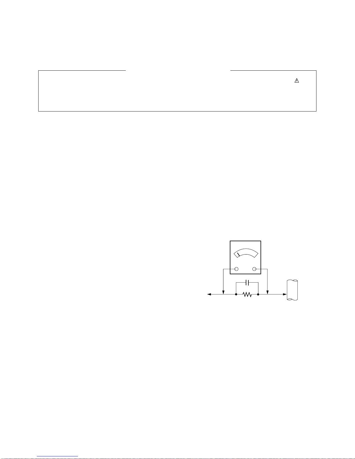
(1) Because this is not a hot chassis, it is not necessary to use
an isolation transformer. However, the use of isolation
transformer will help protect test instrument.
(2) Adjustment must be done in the correct order.
(3) The adjustment must be performed in the circumstance of
25±5°C of temperature and 65±10% of relative humidity if
there is no specific designation.
(4) The input voltage of the receiver must keep 100~240V,
50/60Hz.
(5) The receiver must be operated for about 5 minutes prior to
the adjustment.
OAfter RGB Full White in HEAT-RUN Mode, the receiver
must be operated prior to the adjustment.
OEnter into HEAT-RUN MODE
1) Press the POWER ON KEY on R/C for adjustment.
2) Press the ADJ KEY on R/C and enter EZ ADJUST
Select “3. Test Pattern” by using D/E(CH +/-) and press
ENTER(V)
Select “White” by using F/G(VOL +/-) and press
ENTER(V)
- Set is activated HEAT run without signal generator in this
mode.
- Single color pattern (RED / BLUE / GREEN) of HEAT RUN
MODE uses to check panel.
- Caution: If you turn on a still screen more than 20 minutes
(Especially digital pattern, cross hatch pattern), an after
image may be occur in the black level part of the screen.
[Caution
- Using ‘power on’ button of the control R/C, power on TV.
- All adjustment process is executed through RS-232C.
- Do not connect external input cable.
3. S/W Auto Download Using the
USB Memory Stick
[Caution
- Using ‘power on’ button of the control R/C, power on TV.
- USB file (EPK) version must be bigger than downloaded
version of main B/D.
(1) Insert the USB memory stick to the SET.
(2) Using ‘power on’ button of the control R/C, power on TV.
(3) S/W download process is executed automatically.
4. Auto-control Adjustment is Process
(1) All adjustment process is executed through RS-232C.
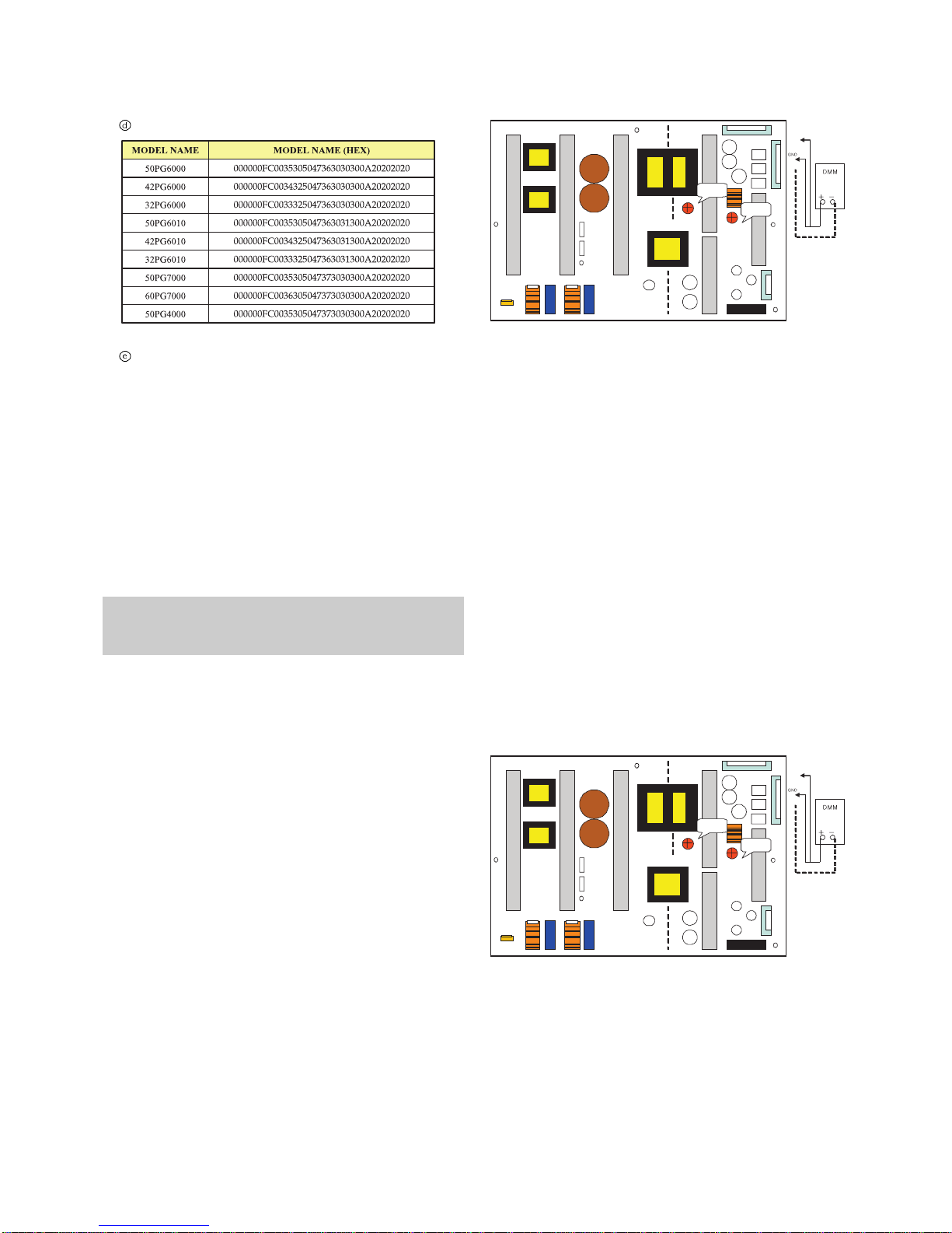
(2) Command send --> ADC Calibration --> Model name
download --> EDID download.
(3) Auto-control adjustment protocol(RS-232C)
(4) Defined model name protocol (RS-232C)

- 8 - LGE Internal Use OnlyCopyright©2008 LG Electronics. Inc. All right reserved.
Only for training and service purposes
5. Manual Model Name Download
(1) Press ADJ key on R/C for model name D/L
(2) Select “. Model Option” and press ENTER(V)
(3) Insert Option value by a number key
(4) Press the ENTER(V)
6. Manual ADC Adjustment
[Caution
- Do not connect external input cable
- Adjustment result is applied to SET On/Off later.
[Adjustment is done using internal ADC, so input signal is
not necessary.
(1) Press ADJ key on R/C for adjustment.
(2) Select “2. ADC calibration” by using D/E(CH +/-) and
press ENTER(V).
(3) Select “Start’ by using F/G(VOL +/-) and press
ENTER(V).
(4) ADC adjustment is executed automatically.
7. Manual EDID Download
(1) Press the ADJ KEY on R/C and enter EZ ADJUST.
(2) Select “5. EDID D/L” by using D/E(CH +/-) and press
ENTER(V).
(3) Select “Start” and press ENTER(V).
(4) EDID download is executed automatically.
(5) Press EXIT key on R/C.
8. EDID Data
(1) HDMI 1 (256 bytes)
(2) RGB (128 bytes)
=> Detail EDID Options are below( , , , )
1. -> Product ID
2. -> Serial No : Controlled on production line
3. -> Month, Year : Controlled on production line
NO SIGNAL or White noise NO SIGNAL
RF Input AV / Component / RGB input

- 9 - LGE Internal Use OnlyCopyright©2008 LG Electronics. Inc. All right reserved.
Only for training and service purposes
4. -> Model Name
5. -> Checksum : Changeable by total EDID data.
9. PCMCIA CARD Checking Method
You must adjust DTV 29 Channel and insert PCMCIA CARD
to socket.
(1) If PCMCIA CARD works normally, normal signals display
on screen.
But it works abnormally, “No CA module” words display on
screen.
[Caution: Set up “RF mode” before launching products.
Caution: Set up “RF mode(noise)” before voltage adjustment.
- Test equipment: D.M.M 1EA
- Connection Diagram for Measuring: refer to fig.1, fig 2, fig 3. fig 4
10. 50” POWER PCB Ass’y Voltage
Adjustment(Va, Vs voltage Adjustment)
10-1. Model name: 50PG6000, 50PG6010
10-2. Adjustment Method
(1) 50” Va Aadjustment (refer fig. 1)
1) After receiving 100% Full White Pattern, HEAT RUN.
2) Connect + terminal of D. M.M. to Va pin of P811,
connect -terminal to GND pin of P811.
3) After turning VR901,voltage of D.M.M adjustment as
same as Va voltage which on label of panel right/top
(deviation; ±0.5V)
(2) 50” Vs Adjustment (refer fig. 1)
1) Connect + terminal of D. M..M. to Vs pin of P811,
connect -terminal to GND pin of P811.
2) After turning VR951, voltage of D.M.M adjustment as
same as Vs voltage which on label of panel right/top(
deviation ; ±0.5V)
11. 42” POWER PCB Ass’y Voltage
Adjustment(Va, Vs voltage Adjustment)
11-1. Model name: 42PG6000, 42PG6010
11-2. Adjustment Method
(1) 42” Va Adjustment (refer fig. 2)
1) After receiving 100% Full White Pattern, HEAT RUN.
2) Connect + terminal of D. M..M. to Va pin of P811,
connect -terminal to GND pin of P811.
3) After turning VR901,voltage of D.M.M adjustment as
same as Va voltage which on label of panel right/top
(deviation; ±0.5V)
(2) 42” Vs Adjustment (refer fig. 2)
1) Connect + terminal of D. M..M. to Vs pin of P811,
connect -terminal to GND pin of P811.
2) After turning VR951, voltage of D.M.M adjustment as
same as Vs voltage which on label of panel right/top(
deviation ; ±0.5V)
Caution: Each PCB assembly must be checked by check JIG
set. (Because power PCB Assembly damages to PDP Module,
especially be careful)
P812
P811
P813
Vs adj
Va adj
VR951
SC101
VR901
Va
GND
5V
Vs
(Fig. 1) 50inch Power PCB Assy Voltage Adjustment
P812
P811
P813
Vs adj
Va adj
VR951
SC101
VR901
Va
GND
5V
Vs
(Fig. 2) 42inch Power PCB Assy Voltage Adjustment

- 10 - LGE Internal Use OnlyCopyright©2008 LG Electronics. Inc. All right reserved.
Only for training and service purposes
12. 60”(FHD), 50”(FHD) POWER PCB
Ass’y Voltage Adjustment
(Va, Vs voltage Adjustment)
12-1. Model name:50PG7000, 60PG7000, 50PG4000
12-2. Adjustment Method
(1) 60”FHD Va Adjustment (refer fig. 3)
1) After receiving 100% Full White Pattern, HEAT RUN.
2) Connect + terminal of D. M..M. to Va pin of P11, connect
-terminal to GND pin of P11.
3) After turning VR901,voltage of D.M.M adjustment as
same as Va voltage which on label of panel right/top
(deviation; ±0.5V)
(2) 60”FHD Vs Adjustment (refer fig. 3)
1) Connect + terminal of D. M..M. to Vs pin of P11, connect
-terminal to GND pin of P11.
2) After turning VR951, voltage of D.M.M adjustment as
same as Vs voltage which on label of panel right/top(
deviation ; ±0.5V)
13. 32”(XGA) POWER PCB Ass’y
Voltage Adjustment
(Va, Vs voltage Adjustment)
13-1. Model name:32PG6000, 32PG6010
13-2. Adjustment Method
(1) 32”Va Adjustment (refer fig. 4)
1) After receiving 100% Full White Pattern, HEAT RUN.
2) Connect + terminal of D. M.M. to Va pin of P811,
connect -terminal to GND pin of P811.
3) After turning VR901,voltage of D.M.M adjustment as
same as Va voltage which on label of panel right/top
(deviation; ±0.5V)
(2) 32”Vs Adjustment (refer fig. 4)
1) Connect + terminal of D. M..M. to Vs pin of P811,
connect -terminal to GND pin of P811.
2) After turning VR951, voltage of D.M.M adjustment as
same as Vs voltage which on label of panel right/top(
deviation ; ±0.5V)
- Before adjusting White-balance , the AV ADC should be done.
- If ADC status were “NG”, Need to ADC adjustment.
14. Adjustment of White Balance
Caution: Press the POWER ON KEY on R/C before W/B
adjustment.
14-1. Test Equipment
- Color Analyzer (CS-1000, CA-100+(CH.10), CA-210(CH.10))
[Please adjust CA-100+ / CA-210 by CS-1000 before
measuring
--> You should use Channel 10 which is Matrix
compensated (White, Red, Green, Blue revised) by CS-
1000 and adjust in accordance with White balance
adjustment coordinate.
OColor temperature standards according to CSM and Module
OChange target luminance and range of the Auto adjustment
W/B equipment.
(Fig. 3) 60inch FHD Power PCB Assy Voltage Adjustment
(Fig. 4) 32inch Power PCB Assy Voltage Adjustment

OWhite balance adjustment coordinate and color temperature
PC (for communication through RS-232C) ==> UART Baud
rate : 115200 bps
14-2. Connecting Picture of the Measuring
Instrument(On Automatic control )
Inside PATTERN is used when W/B is controlled. Connect to
auto controller or push control R/C INSTART —> Enter the
mode of White-Balance, the pattern will come out.
14-3. Auto-control Interface and Directions
(1) Adjust in the place where the influx of light like floodlight
around is blocked. (illumination is less than 10ux).
(2) In case of PDP: Measure and adjust after sticking the
Color Analyzer (CA-100+, CA210) to the side of the
module.
In case of LCD: Adhere closely the Color Analyzer (
CA210 ) to the module less than 10cm distance, keep it
with the surface of the Module and Color Analyzer’s Prove
vertically.(80~100°).
(3) Aging time
1) After aging start, keep the power on (no suspension of
power supply) and heat-run over 5 minutes.
2) In case of PDP, keep white pattern using inside pattern.
3) In case of LCD, using ’no signal’or ‘full white pattern’or
the others, check the back light on.
OAuto Adjustment Map(RS-232C)
14-4. Manual White Balance
1) Zero Calibrate CA-100+ / CA-210, and when controlling,
stick the sensor to the center of PDP module surface.
2) Press the ADJ KEY on R/C and enter EZ ASJUST
Select “2. White Balance”and press G(VOL +)
Set test-pattern on and display inside pattern.
3) Control is carried out on three color temperatures, COOL,
MEDIUM, WARM.
(Control is carried out three times)
<Temperature: COOL>
- R-Cut/ G-Cut / B-Cut is set to 64
- Control R-Gain and G-Gain.
- Each gain is limited to 192
<Temperature: MEDIUM>
- R-Cut/ G-Cut / B-Cut is set to 64
- Control R-Gain and G-Gain.
- Each gain is limited to 192
<Temperature: WARM>
- R-Cut/ G-Cut / B-Cut is set to 64
- Control G-Gain and B-Gain.
- Each gain is limited to 192
- 11 - LGE Internal Use OnlyCopyright©2008 LG Electronics. Inc. All right reserved.
Only for training and service purposes

- 12 - LGE Internal Use OnlyCopyright©2008 LG Electronics. Inc. All right reserved.
Only for training and service purposes
TROUBLE SHOOTING GUIDE
1. Power Board
1-1. The whole flowchart which it follows in voltage output state
Start check
Manufacture enterprise
meaning of a passage
1. Check the Power Off
condition.
Doesn't the
screen whole come
out?
Is it identical
with Power Off
condition?
Yes
Yes
No
No
No
No
No
2. Check the Interface
signal condition.
Is the Interface
signal operated?
Yes
3. Check the St-by 5V
signal circuit.
Doesn't the
low pressure output
come out?
Doesn't the
St-by 5V signal
come out?
Yes
Yes
No
4. Check the 5V Monitor
signal circuit.
Doesn't the
5V Monitor signal
come out?
Yes
7. Check the VSC Vs-ON
signal
Doesn't the
high tension output
come out?
Doesn't the
VSC signal Vs-ON
come out?
Yes
Yes
Does
high tension
output voltage Drop
occur?
When the
Y B/D Module
input connector is
removed, does output
voltage drop
occur?
When the
Y, Z B/D Module
input connector is remove,
does Power Board hightension
output voltage Drop
occur?
Yes No No
9. Check the Power
Board Output high
tension circuit
Yes
10. Check the Z B/D
Module output circuit
Yes
When the
Z B/D Module
input connector is
removed, does output
voltage Drop
occurs?
11. Check the Y B/D
Module output circuit
Yes
No
8. Check the Vs, Va
voltage output circuit.
Doesn't the
Vs, Va voltage output
come out?
Yes
No
No
5. Check the VSC RL-ON
signal.
Doesn't the
VSC signal RL-ON
come out?
Yes
6. Check the VSC low
pressure output
Doesn't the
VSC low pressure
output come out?
Yes

- 13 - LGE Internal Use OnlyCopyright©2008 LG Electronics. Inc. All right reserved.
Only for training and service purposes
1-2. Power Board Structure
(1) Pin Layout
(2) Pin Spec

- 14 - LGE Internal Use OnlyCopyright©2008 LG Electronics. Inc. All right reserved.
Only for training and service purposes
2. No Power
(1) Symptom
1) Doesn’t minute discharge at module.
2) Non does not come in into the front LED.
(2) Check following
A Power cord is plugged with TV set? Plug in power cord.
Yes
No
Is the AC-INLET connected with
the power board? Connect the AC-INLET
Yes
No
Is the Fuse(F101,F801) on
Power Board normal? Replace the Fuses.
Yes
No
Is the Power Board with
VSC Board though Cable connected? Connect the Cable.
Yes
No
Measure output voltages(16V,12V,5V) on the power board.
If the measured values is not normal, replace power board.

- 15 - LGE Internal Use OnlyCopyright©2008 LG Electronics. Inc. All right reserved.
Only for training and service purposes
3. Protect Mode
(1) Symptom
1) After once shining, it does not discharge minutely
from module.
2) The Rely falls.(The sound is audible “click”)
3) It is converted with the color where the front LED
is red from green.
(2) Check following
Is the Power Board
normal ? Replace Power
Board.
Is output the normality Low/High
voltage except Stand-by 5V?
Yes
No No
Is the each connector
normal? Replace the
connector.
Replace
Y-Board.
After connecting well each connector,
the normality it operates?
Yes
No Yes
Is the Ctrl Board
normal? Replace
X-Board.
Is the output voltage normal after
remove P163 connector of Ctrl-B/D?
Yes
No Yes
Is the Y-Board
normal?
Is the output voltage
normal after remove
P209 connector of
Y-B/D?
Is the Fuse(FS201) on Y-B/D
normal?(In case of open is replace)
Yes
No Yes Yes
Replace
Z-Board.
Is the Z-Board
normal?
Is the output voltage
normal after remove
P3 connector of Z-
B/D?
Is the Fuse (FS1) on Z-B/D normal?
(In case of open is replace)
Yes
No Yes
Is the X- Board
normal?
Is the output voltage normal after
remove P242 connector of
X-B/D?
After remove P211 output voltage normality:
Replace Right X-B/D
After remove P23 output voltage normality:
Replace Left X-B/D
Yes
No Yes
Is the
VSC Board normal? Is the output voltage normal after
remove P1001 of VSC Board?
After crisis COF of each board, check the normality operates.
If in case normality operates, correspondence COF Fail is replace the module.
After remove P1001 normal operation:
Replace VSC Board
Yes
No
Is the COF of X, Y, Z
normal ?
No
Yes
Yes

- 16 - LGE Internal Use OnlyCopyright©2008 LG Electronics. Inc. All right reserved.
Only for training and service purposes
Does minute discharge
At Module?
Is the LVDS cable
connect well from Ctrl
Board to VSC Borad?
Replace FLI106X0H
IC(IC100)
Is the VaVs normal?
Check the PDP Module
Yes
No
YES
Yes
Reconnect the LVDS
cable in P501
No
Is normal the VSC
Board?
Operates the FLI106X0H(IC100)?
1. Check the Monitor OUT by SCART2 : Connect the another TV SET
2. Check the LVDS clock(R537,R538) on the VSC Borad by Oscilloscope?
Replace the
VSC B/D.
No
NO Replace the
Power board
Is output the normality
Low/High voltage except
stand-by 5V?
NO
4. No Raster
(1) Symptom
1) No OSD and image occur at screen.
2) It maintains the condition where the front LED is green.
(2) Check the followings
Yes
No

- 17 - LGE Internal Use OnlyCopyright©2008 LG Electronics. Inc. All right reserved.
Only for training and service purposes
5. In case of occurring strange screen into specific mode
5-1. In case the OSD does not displayed
(1) Symptom
1) LED is green.
2) The minute discharged continuously becomes Accomplished from module.
(2) Check following
1. Is damage in the LVDS cable?
2. Isn’t the LVDS cable connect well from
Ctrl Board to VSC Board?
Is the VSC Board
normal?
1. Replace cable
2. LVDS Cable connect well from Ctrl Board to VSC Borad
No
Yes
Yes
No
Is the Ctrl Board of Module normal?
1. Check the LED on the Ctrl Board
2. Check the 5V_ON on the Power Board by the DMM.
No
Replace FLI106X0H
IC(IC100)
Operates FLI106X0H(IC100)?
1. Check the Monitor OUT by SCART2 : Connect the another TV set
2. Check the LVDS clock(R240,R243) on the VSC Borad by Oscilloscope?
Replace the
VSC B/D.
Yes
No
Replace the Ctrl B/D

- 18 - LGE Internal Use OnlyCopyright©2008 LG Electronics. Inc. All right reserved.
Only for training and service purposes
5-2. In case of does’t display the screen into specific mode
(1) Symptom
1) The screen does not become the display from specific input mode
(RF, AV, Component, RGB, DVI).
(2) Check following
1) Check the all input mode should become normality display
.
(3) In case of becomes unusual display from RF mode
(4) In the case of becomes unusual display from side S-video/AV mode
Is the Tuner normal? Is the RF Cable connected well?
1. Check the another TV set.
Cable inserts well or Change the RF Cable
Yes
No
No
Operates the FLI106X0H IC(IC100)?
1.Check the Monitor OUT by SCART2 : Connect the another TV SET
2.Check the LVDS clock(R537, R538) on the VSC Board by Oscilloscope?
3.Check the each Input Source. ATV(TV_CVBS : R302), DTV(TU301 Pin23),
S/AV Mode( SIDE_CVBS_IN : R1160), Component/RGB
(COMP_Y, V/HSYNC : R1122, R1174, R1180)
HMDI(SDA/SCL : IC201 Pin29, Pin30), SCART(SC1/2_CVBS_IN : R977, R521)
on the VSC Board by Oscilloscope.
Replace the Tuner(TU301)
No
Is normal the Input voltage, IIC Communication?
1.Check the Input Voltage 5V(L303), 3.3V(L1022), 1.8V(TU301 Pin22)
2. Check the Analog/Digital IIC(A:R334,R335 D:R342, R343)
Yes
Block A
Replace the FLI106X0H
(IC100).
No
Is Video input of the AV Jack (JK700, 707) normal?
1. Check the CVBS signal in AV jack by Oscilloscope
Yes
Check the input source of Equipment
No
Same as Block A

- 19 - LGE Internal Use OnlyCopyright©2008 LG Electronics. Inc. All right reserved.
Only for training and service purposes
(5) In the case of becomes unusual display from Component, RGB mode
(6) In the case of becomes unusual display from HDMI mode
(7) In the case of becomes unusual display from SCART mode
Is R,G,B input and H,V Sync of the JK701, 703 normal?
1. Check the RGB signal/H(V)SYNC in the RGB Cable
Yes
Check the input source of Equipment
Same as Block A
No
Is Video input of A/V jack normal?
Yes
Check the input source.
Same as Block A
No
No
Is the HDMI(IC201)
normal?
Yes
Same as Block A
Is the TMDS waveform between the
IC and HDMI jacks normal? Replace the IC201.
No

- 20 - LGE Internal Use OnlyCopyright©2008 LG Electronics. Inc. All right reserved.
Only for training and service purposes
6. In case of no sound
(1) Symptom
1) LED is Green.
2) Screen display but sound is not output.
(2) Check following
All input(mode) is no
sound?
Only HDMI is No
Sound?
Yes
Download
the EDID data
No
No YES
Only RF is no sound? Check the Tuner IN/OUT
TV_L/R_OUT( R356)
No
Yes
IC601(Audio AMP) operates Normal?
1.Check 1.8V, 3.3V, 16V input Voltage (L607, IC601 Pin8, IC601 Pin32)
2.Check the IIC communication (SDA/SCL : R645, R643)
3.Check the Audio Signal is normal.(SPK_L/R : L603, L604, L606, L610)
Replace the Audio AMP IC
(IC601).
No
No
YES
Replace the VSC Board
Is the speaker On it menu?
1. Menu > Audio > TV Speaker ON/OFF Set on speaker in menu.
(TV Speaker OFF ? ON)
No
Is the speaker Cable normal?
1. Isn’t damage in the Speaker Cable?
2. Is the Speaker cable connect well form VSC B/D to Speaker.
Change or Reconnect the
Speaker Cable.
Yes
Only RF is no sound? Replace the VSC B/D
Yes
Yes
Check the Input Sound IN/OUT
AV1(SC1_LIN : R1140, SC1_RIN : R1134)
AV1(SC2_LIN : R1146, SC2_RIN : R1145)
AV3(SIDE_LIN : R1306, SIDE_RIN: R1307 )
PC(PC_LIN: R631, PC_RIN : R630)
Component (COMP_LIN : R1178, COMP_RIN: R1179)
No
Other manuals for 32PG6000
1
This manual suits for next models
9
Table of contents
Other LG Plasma TV manuals