- 8 - LGE Internal Use OnlyCopyright ©2011 LG Electronics Inc. All rights reserved.
Only or training and service purposes
4. SET assembly adjustme t method
* Caution : Each PCB assembly must be checked by check JIG
set. (Because power PCB Assembly damages to PDP
Module, especially be care ul)
4-1.POWER PCB Assembly Voltage
adjustme t (Va/Vs Voltage Adjustme t)
Test equipment : D.M.M 1EA
Connection Diagram or Measuring : re er to ig.4
Adjustment method
(1) Va adjustment
1) Connect + terminal o D. M.M. to Va pin o P811,
connect -terminal to GND pin o P811.
2) A ter turning VR901,voltage o D.M.M adjustment as
same as Va voltage which on label o panel right/top
(deviation; ±0.5V)
(2) Vs adjustment
1) Connect + terminal o D. M..M. to Vs pin o P811,
connect -terminal to GND pin o P811.
2) A ter turning VR951, voltage o D.M.M adjustment as
same as Vs voltage which on label o panel right/top (
deviation ; ±0.5V)
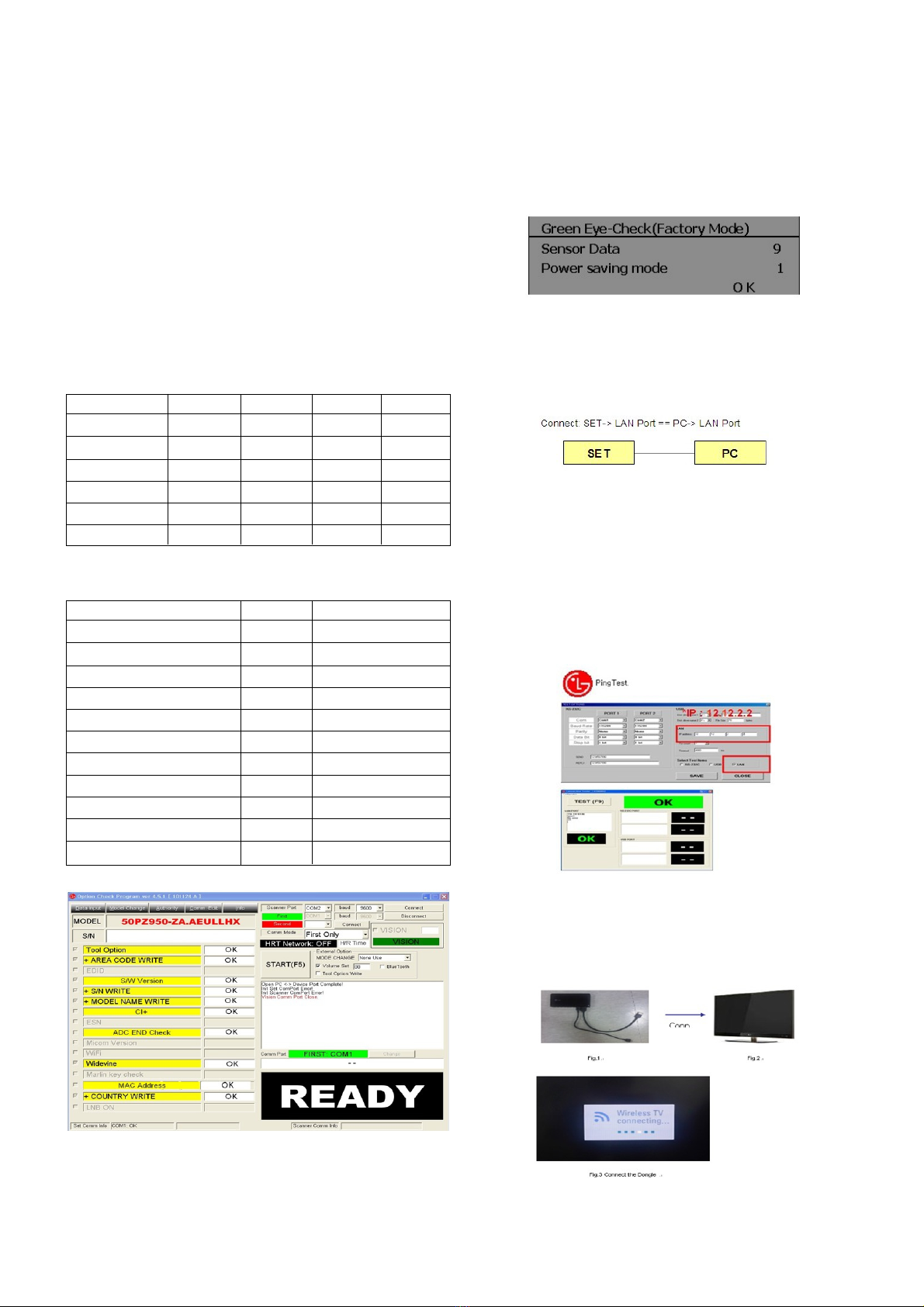
4-2. Dow load Serial umber (RS-232C)
VPress “Power on” key o service R/C.
(Baud rate : 115200 bps)
VConnect RS232 Signal Cable to RS-232 Jack.
VWrite Serial number by use RS-232.
VMust check the serial number at the Diagnostics o SET UP
menu. (Re er to below ‘6.SET INFORMATION’).
4-3. Adjustme t of White Bala ce
Required Equipment
ORemote controller or adjustment
OColor Analyzer ( CS-1000, CA-100,100+,CA-210 or same
produc: CH 10 (PDP)
* Please adjust CA-210, CA-100+ by CS-1000 be ore
measuring
OAuto W/B adjustment instrument(only or Auto adjustment)
O9 Pin D-Sub Jack(RS232C) is connected to the AUTO W/B
EQUIPMENT.
Before Adjust of White Bala ce, Please press POWER ONLY
key
Adjust Process will start by execute RS232C Command.
O Color temperature standards according to CSM and Module
OCS-1000/CA-100+/CA-210(CH 10) White balance
adjustment coordinates and color temperature.
* Manual W/B process (using adjusts Remote control)
Please Adjust in AV 1 MODE, Turn o Energy Saving Mode.
(1) Enter ‘PICTURE RESET’ on Picture Mode, then turn o
Fresh Contrast and Fresh colour in Advanced Control
(2) A ter enter Service Mode by pushing “ADJ” key,
(3) Enter White Pattern o o service mode, and change o ->
on.
(4) Enter “W/B ADJUST” by pushing “G” key at “3. W/B
ADJUST”.
* Gain Max Value is 192. So, Never make any Gain Value over
192 and please ix one Value on 192, between R, G and B.
* Auto-control inter ace and directions
(1) Adjust in the place where the in lux o light like loodlight
around is blocked. (Illumination is less than 10ux).
(2) Measure and adjust a ter sticking the Color Analyzer (CA-
100+, CA210 ) to the side o the module.
(3) Aging time
A ter aging start, keep the Power on (no suspension o
power supply) and heat-run over 5 minutes
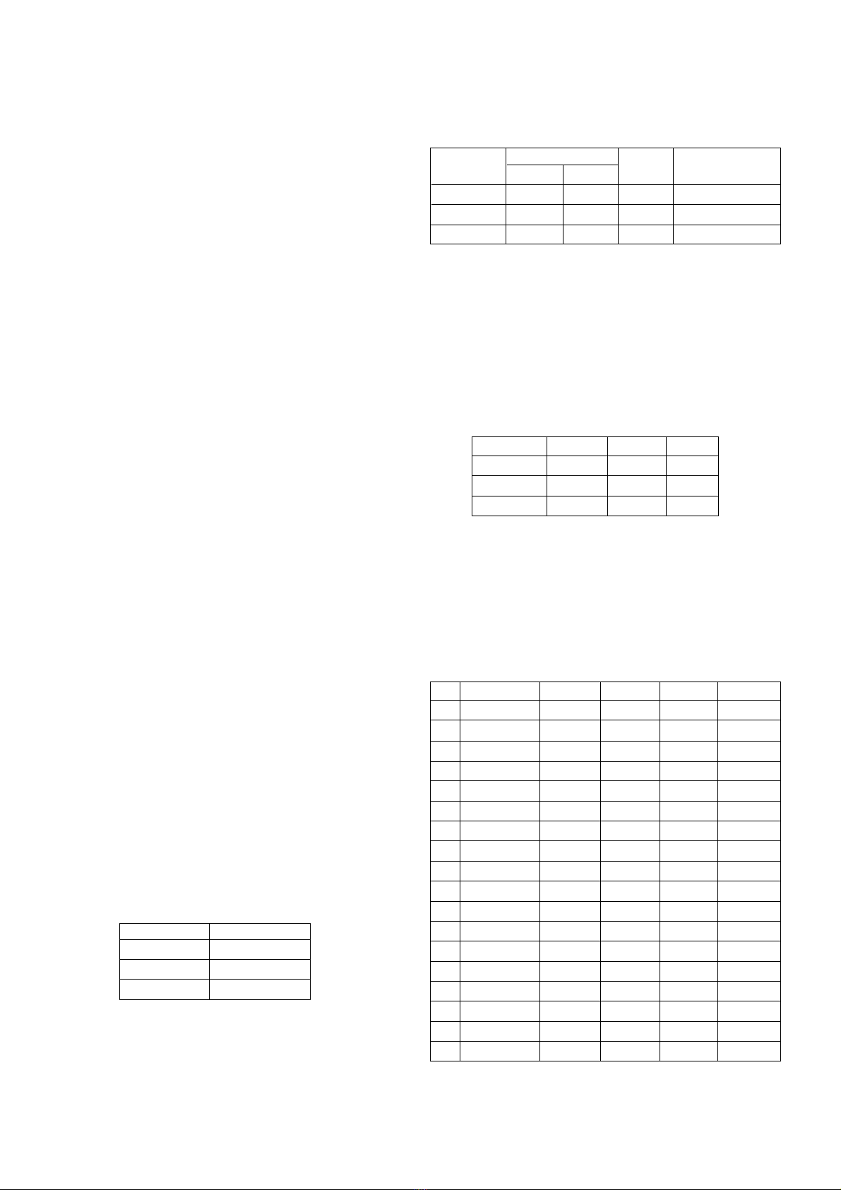
O Auto adjustment Map (RS232C)
CSM PLASMA
Cool 11000K
Medium 9300K
Warm 6500K
CSM Color Coordinate Temp ±Color Coordinate
xy
Cool 0.276 0.283 11000K 0.002
Medium 0.285 0.293 9300K 0.002
Warm 0.313 0.329 6500K 0.002
Min Tpy Max
R-GAIN 0 192 192
G-GAIN 0 192 192
B-GAIN 0 192 192
No Index CMD1 CMD2 Set ID Data
1 Start w b 0 00
2 Gain Start w b 0 10
3 Gain End w b 0 1F
4 O set Start w b 0 20
5 O set End w b 0 2F
6 End w b 0 FF
7 Medium R j a 0 00~FF
8 Medium G j b 0 00~FF
9 Medium B j c 0 00~FF
10 Warm R j d 0 00~FF
11 Warm G j e 0 00~FF
12 Warm B j 0 00~FF
13 Cool R j g 0 00~FF
14 Cool G j h 0 00~FF
15 Cool B j i 0 00~FF
16 Cool R,G,B j j 0 00~FF
17 Medium j k 0 00~FF
18 Warm j l 0 00~FF