LG 60PC1D - - 60" Plasma TV User manual

PLASMA TV
SERVICE MANUAL
CAUTION
BEFORE SERVICING THE CHASSIS,
READ THE SAFETY PRECAUTIONS IN THIS MANUAL.
CHASSIS : PB61A
MODEL : 60PC1D 60PC1D-AA
website:http://biz.LGservice.com
All manuals and user guides at all-guides.com
all-guides.com

- 2 -
CONTENTS
SAFETY PRECAUTIONS ....................................................................................3
SPECIFICATIONS ................................................................................................4
ADJUSTMENT INSTRUCTIONS .........................................................................6
TROUBLE SHOOTING GUIDE ..........................................................................11
BLOCK DIAGRAM.............................................................................................17
EXPLODED VIEW..............................................................................................18
EXPLODED VIEW PARTS LIST ........................................................................19
REPLACEMENT PARTS LIST...........................................................................20
SCHEMATIC DIAGRAM.........................................................................................
PRINTED CIRCUIT DIAGRAM ..............................................................................
All manuals and user guides at all-guides.com

- 3 -
SAFETY PRECAUTIONS
Many electrical and mechanical parts in this chassis have special safety-related characteristics. These parts are identified by in the
Schematic Diagram and Replacement Parts List.
It is essential that these special safety parts should be replaced with the same components as recommended in this manual to prevent
X-RADIATION, Shock, Fire, or other Hazards.
Do not modify the original design without permission of manufacturer.
General Guidance
An isolation Transformer should always be used during the
servicing of a receiver whose chassis is not isolated from the AC
power line. Use a transformer of adequate power rating as this
protects the technician from accidents resulting in personal injury
from electrical shocks.
It will also protect the receiver and it's components from being
damaged by accidental shorts of the circuitry that may be
inadvertently introduced during the service operation.
If any fuse (or Fusible Resistor) in this monitor is blown, replace it
with the specified.
When replacing a high wattage resistor (Oxide Metal Film Resistor,
over 1W), keep the resistor 10mm away from PCB.
Keep wires away from high voltage or high temperature parts.
Due to high vacuum and large surface area of picture tube,
extreme care should be used in handling the Picture Tube.
Do not lift the Picture tube by it's Neck.
Leakage Current Cold Check(Antenna Cold Check)
With the instrument AC plug removed from AC source, connect an
electrical jumper across the two AC plug prongs. Place the AC
switch in the on position, connect one lead of ohm-meter to the AC
plug prongs tied together and touch other ohm-meter lead in turn to
each exposed metallic parts such as antenna terminals, phone
jacks, etc.
If the exposed metallic part has a return path to the chassis, the
measured resistance should be between 1MΩand 5.2MΩ.
When the exposed metal has no return path to the chassis the
reading must be infinite.
An other abnormality exists that must be corrected before the
receiver is returned to the customer.
Leakage Current Hot Check (See below Figure)
Plug the AC cord directly into the AC outlet.
Do not use a line Isolation Transformer during this check.
Connect 1.5K/10watt resistor in parallel with a 0.15uF capacitor
between a known good earth ground (Water Pipe, Conduit, etc.)
and the exposed metallic parts.
Measure the AC voltage across the resistor using AC voltmeter
with 1000 ohms/volt or more sensitivity.
Reverse plug the AC cord into the AC outlet and repeat AC voltage
measurements for each exposed metallic part. Any voltage
measured must not exceed 0.75 volt RMS which is corresponds to
0.5mA.
In case any measurement is out of the limits specified, there is
possibility of shock hazard and the set must be checked and
repaired before it is returned to the customer.
Leakage Current Hot Check circuit
1.5 Kohm/10W
To Instrument's
exposed
METALLIC PARTS
Good Earth Ground
such as WATER PIPE,
CONDUIT etc.
AC Volt-meter
IMPORTANT SAFETY NOTICE
0.15uF
All manuals and user guides at all-guides.com

SPECIFICATIONS
NOTE : Specifications and others are subject to change without notice for improvement
.
VApplication Range
This spec is applied to the 360” PLASMA TV used PB61A Chassis.
V Specification
Each part is tested as below without special appointment.
1) Temperature : 25±5°C (77±9°F), CST : 40±5
2) Relative Humidity: 65±10%
3) Power Voltage: Standard Input voltage (100-240V~, 50/60Hz)
* Standard Voltage of each product is marked by models.
4) Specification and performance of each parts are followed each drawing and specification by part number in accordance with SBOM.
5) The receiver must be operated for about 20 minutes prior to the adjustment.
VTest Method
1) Performance : LGE TV test method followed.
2) Demanded other specification
Safety : CB specification
EMC : CISPR 13 specification
VGeneral Specification
1. Module Specification(PDP60X6)
- 4 -
Display area
Outline dimension
Number of Pixels
Cell pitch
Color arrangement
Weight(net)
Weight(gross)
Operation Environment Temperature
Humidity
Pressure
Storage Environmnet Temperature
Humidity
Pressure
I mage stick minimization Start time
mode Low Brightness
Arrival Time
1319.6 (H) * 741.9(V) °± 0.5
1408 (H) x 828 (V) x 61 (D)° ± 1
1366 (H) x 768(V)
322um (H) x 966um (V)
RGB closed type
32.0 33.0 32.0
122.0 123.0 124.0
0 ~ 40
20 ~ 80
800 ~ 1100
-20 ~ 60
10 ~ 90
700 ~ 1100
4.5 5 5.5
14 15 16
1
2
3
4
5
6
7
8
9
10
No Item Remark
1Pixel=3RGB Cells
Green Cell basis
5EA 1 Box
Altitude : 0 to 2000M
Altitude : 0 to 3000M
Chassis
PB61A 60PC1D-AA Australia LG
Model Name Market Brand Remark
60PC1D-AA Safety : IEC60065,EN60065
EMC : CISPR 13 Class B
Australia
Model ApplianceMarket Remark
mm
mm
um
Kg
Kg
deg
%
hPa
deg
%
hPa
min
min
Min Typ Max Unit
All manuals and user guides at all-guides.com

- 5 -
2. Model General Specification
Broadcasting system
Available Channel
Tuner IF
Input Voltage
PDP Module
Aspect ratio
Operating Temperature
Operating Humidity
Storage Temperature
Storage Humidity
PAL-B/G, DTV : DVB-T
1) VHF : 00 ~ 12
2) UHF : 20 ~ 75
3) CATV : 02 ~ 44
4) DTV : 06 ~12, 27 ~ 69
1) PAL : 38.90MHz(Picture),
34.40MHz(Sound)
2) DVB-T : 36.125MHz
240V~, 50Hz
PDP60X6
16:9 (wide)
0 40 deg
85 %
-20 60 deg
85 %
1
2
3
4
5
6
7
8
9
10
No Item
Remark
Maker : LGE
? Closed Type
Specification
Min Typ Max Unit
All manuals and user guides at all-guides.com

- 6 -
ADJUSTMENT INSTRUCTIONS
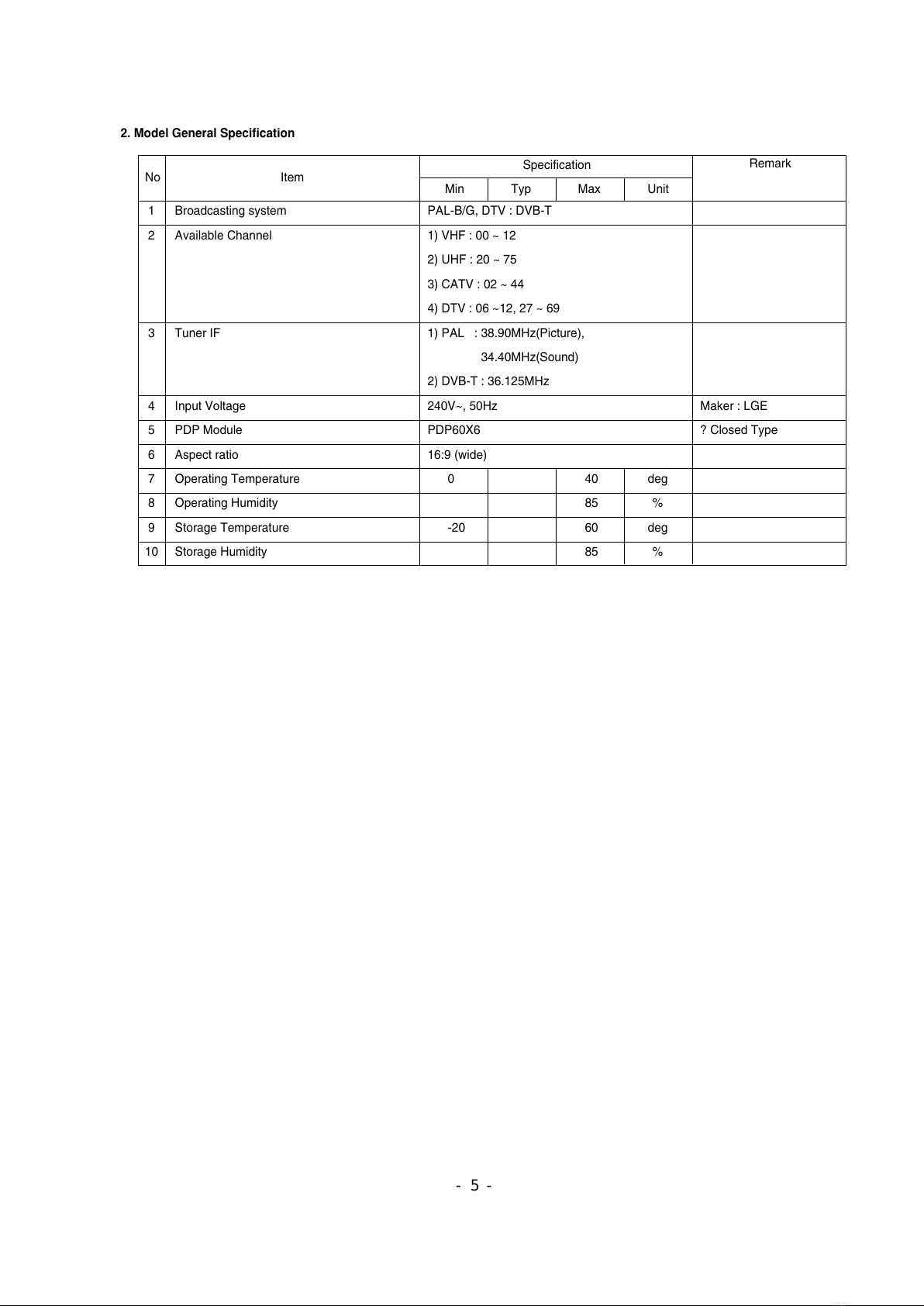
1. Application Object
These instructions are applied to all of the 60” PLASMA TV,
PB61A
Chassis.
2. Notes
(1) Because this is not a hot chassis, it is not necessary to use
an isolation transformer. However, the use of isolation
transformer will help protect test equipment.
(2) Adjustments must be done in the correct order.
(3) The adjustments must be performed in the circumstance of
25±5°C of temperature and 65±10% of relative humidity if
there is no specific designation.
(4) The input voltage of the receiver be must kept 220V~,
60Hz when adjusting.
(5) The receiver must be operational for about 15 minutes
prior to the adjustments.
OPreliminary action is applied to the test for afterimage
discharge detection, and 100% FULL WHITE PATTERN
must be operated automatically.
OTest for afterimage discharge detection
1) After pressing Power Only key(only operating by
pressing Power Only key), Full Test Pattern(2 min
30sec) --> Full Black Pattern(30sec) --> After this state,
Full White Pattern is displayed.
(but you must preset the program for Full White State
when you press the Main Power Off/On)
2) Pattern Mode is deselected by pressing CH +/-, Exit Key.
[Set is activated HEAT-RUN without signal generator in
this mode.
3. CPLD Download
(1) Test Equipment: PC, Jig for download
(2) Connect the power of VSC B/D.
(3) Execute download program of PC.
(4) After executing the hot key on the Programmer, click icon.
(5) End after confirming.
4. Sub-ucom(MTV) Download
(1) Test Equipment: PC, Jig for download
(2) Connect the power of VSC B/D.
(3) Execute download program of PC.
(4) After executing the hot key on the Programmer, click icon.
(5) End after confirming.
5. MST3362M-Set Adjustment
5-1. Synopsis
MST3362M-Set adjustment to set the black level and the Gain
of optimum with an automatic movement from the analog =>
digital converter.
5-2. Test Equipment
Service R/C, 801GF(802B,802F,802R),
MSPG-925 Pattern Generator.
( 480i, 1080i 60Hz Color Bar Pattern output will be possible
and the output level will accurately have to be revised with
0.7±0.1Vp-p)
5-3. Adjustment
(1) How to adjustment the Component1
1) Select Component1 as the input with Color Bar Pattern
in 480i 60Hz mode and select ‘Component1’ on screen.
2) After receiving signal for at least 1 second, press the
ADJ Key on the Service R/C to enter the ‘Ez - Adjust’
and select the ‘1. ADC 480i Comp1’. Pressing the Vol+
Key to adjust the component1.
3) When the adjustment is over, 'Component1 Adjustment
OK’ is displayed. If the adjustment has errors,
'Component1 Adjustment Failed! Try Again!’ is
displayed.
4) Readjust after confirming the case Pattern or adjustment
condition where the adjustment had errors.
5) After adjustment is complete, exit the adjustment mode
by pressing the ADJ KEY.
(2) How to adjustment the Component2, RGB
1) Select Component2, RGB-DTV as the input with Color
Bar Pattern in 1080i 60Hz mode and select
‘Component2’ on screen.
2) After receiving signal for at least 1 second, press the
ADJ Key on the Service R/C to enter the ‘Ez - Adjust’
and select the ‘2. ADC 1080i Comp2/RGB’. Pressing
the Vol+ Key to adjust the component2.
3) When the adjustment is over, 'Component2 Adjustment
OK’ is displayed. If the adjustment has errors,
'Component2 Adjustment Failed! Try Again!’ is
displayed. and If the adjustment has errors, 'RGB
Adjustment Failed! Try Again!’ is displayed.
4) Readjust after confirming the case Pattern or adjustment
condition where the adjustment had errors.
5) After adjustment is complete, exit the adjustment mode
by pressing the ADJ KEY.
PC
VSC
B/D
JIG cable(CPLD D/L )
<Fig. 1> Connection Diagram of CPLD Download
(Fig. 2) Adjust Pattern : 480i, 1080i 60Hz Color Bar Pattern
Caution) If you turn on a still screen more than 20 minutes
(Especially Digital pattern, Cross Hatch Pattern), an afterimage
may occur in the black level part of the screen.
All manuals and user guides at all-guides.com
all-guides.com

- 7 -
6. Video(uPD)-Set
6-1. Synopsis
This is a adjustment to reduce the color difference of video
signal Main/Sub Display.
6-2. Required Equipment
Service R/C, MSPG-925 Pattern Generator.
(It’s available to output the Color Bar Pattern of the NTSC,PAL)
6-3. Adjustment
(1) How to adjustment the uPD PAL
1) Select AV1 as the input with 100% 8 Color Bar Pattern
in PAL mode and select ‘AV1’ on screen.
2) After receiving signal for at least 1 second, press the
ADJ Key on the Service R/C to enter the ‘Ez - Adjust’
and select the ‘3. uPD PAL(Main&Sub)-Set’. Pressing
the Vol+ Key to adjust the uPD PAL.
3) When the adjustment is over, 'uPD64015 PAL Main
Adjustment OK’ and ‘uPD64015 PAL Sub Adjustment
OK’ is displayed. If the adjustment has errors,
'uPD64015 PAL Main Error!’ or 'uPD64015 PAL Main
Error!’ is displayed.
4) Readjust after confirming the case Pattern or adjustment
condition where the adjustment had errors.
5) After adjustment is complete, exit the adjustment mode
by pressing the ADJ KEY.
(2) How to adjustment the uPD NTSC
1) Select AV1 as the input with 100% 8 Color Bar Pattern
in NTSC mode and select ‘AV1’ on screen.
2) After receiving signal for at least 1 second, press the
ADJ Key on the Service R/C to enter the ‘Ez - Adjust’
and select the ‘4. uPD NTSC(Main&Sub)-Set’. Pressing
the Vol+ Key to adjust the uPD NTSC.
3) When the adjustment is over, 'uPD64015 NTSC Main
Adjustment OK’ and ‘uPD64015 NTSC Sub Adjustment
OK’ is displayed. If the adjustment has errors,
'uPD64015 NTSC Main Error!’ or 'uPD64015 NTSC
Main Error!’ is displayed.
4) Readjust after confirming the case Pattern or adjustment
condition where the adjustment had errors.
5) After adjustment is complete, exit the adjustment mode
by pressing the ADJ KEY.
7. POWER PCB Assy Voltage
Adjustment (Va, Vs Voltage Adjustment)
7-1. Test equipment: D.M.M 1EA
7-2. Connection Diagram for Measuring
Refer to Fig.5
7-3. Adjustment Method
Adjustment Method for Power Board( P/No: EAY32961801)
(1) Va Adjustment
1) After receiving 100% Full White Pattern, HEAT RUN.
2) Connect + terminal of D.M.M to Va pin of P812, connect
- terminal to GND pin of P812.
3) After turning VR901, voltage of D.M.M adjustment as
same as Va voltage which on label of panel right/top.
(Deviation; ±0.5V)
(2) Vs Adjustment
1) Connect + terminal of D.M.M to Vs pin of P812, connect
– terminal to GND pin of P812.
2) After turning VR951, voltage of D.M.M adjustment as
same as Va voltage which on label of panel right/top.
(Deviation; ±0.5V)
(Fig. 3) Adjust Pattern :100% 8 Color Bar Pattern
Each PCB Assy must be checked by Check JIG Set before
assembly. (Especially, be careful Power PCB Assy which can
cause Damage to the PDP Module.)
(Fig. 5) Connection Diagram of Power Adjustment for Measuring
All manuals and user guides at all-guides.com

- 8 -
8. EDID(The Extended Display
Identification Data)/DDC
(Display Data Channel) Download
This is the function that enables “Plug and Play".
8-1. Required Test Equipment
(1) PC, Jig for adjusting DDC.
(PC serial to D-sub Connection equipment)
(2) DVI to HDMI Connector.
8-2. Setting of Device
8-3. EDID DATA
(1) HDMI EDID DATA.
(2) RGB EDID DATA.
8-4. Act or set the EDID S/W
1) As above Fig. 6, Connect the Set, EDID Download Jig, PC
& Cable.
2) Turn on the PC & EDID Download Jig. And Execute the
S/W : EDID TESTER Ver,2.5.
3) Set up S/W option.
Repeat Number : 3
Device Address : A0
PageByte : 8
8-5. How to use the EDID S/W
1) Init the data.
2) Load the EDID data.(Open File)
3) Press the “Write Data & Verify”button. and input the
data.
4) If the writing is finished, you will see the “OK” message.
Analog EDID
D-sub to D-sub
HDMI EDID
DVI-D to HDMI
PC
JIG
PDP
SET
RGB
(Analog)
67
Checksum
Model
60PC1D-AA
HDMI
(Digital)
3724
All manuals and user guides at all-guides.com

- 9 -
9. Adjustment of White Balance
9-1. Required Equipment
(1) Color analyzer (CA-100 or similar product)
(2) Automatic adjustor (with automatic adjustment hour
necessity and the RS-232C communication being possible)
9-2. Connection Diagram of Equipment
for Measuring (Automatic Adjustment)
9-3. Process of automatic adjustment
(1) As using the white pattern for adjustment the inner part,
HDMI connection need not. But as lower part, the RS-232C
Command is used.
Wb 00 00 Automatic adjustment of white balance start.
Wb 00 10 The start of gain adjustment.(inside pattern)
Ja 00 ff Adjustment Date.
Jb 00 c0
...
Wb 00 1f The end of gain adjustment.
As occasion demands , adjust the offset.
( Wb 00 20(Start) , Wb 00 2f(end))
Wb 00 ff Automatic adjustment of white balance end.
(Disappear the inside pattern)
Caution) When you adjust, automatically, RS-232C
Command is used.
[[RS-232C Command (Automatic Adjustment)
9-4. Adjustment of White Balance
(Automatic Adjustment)
O
Calibrate of the CA-100, then attach sensor to PDP module
surface when you adjust.
O
Manual adjustment is also possible by the following sequence.
(1) HEAT RUN at least 30 minutes by pressing the Power only
Key on the Service Remote Control and adjust. and use
power only or tint key and establish BaudRate to 115200.
(2) It must start “ 00 00”, complete “wb 00 ff”.
(3) Adjust offset.
9-5. Adjustment of White Balance
(Passivity Adjustment)
(1) HEAT RUN at least 30 minutes by pressing the ‘7. White-
Pattern’ on the Service Remote Control and adjust.
(2) After attaching sensor to center of screen, select ‘6. White-
Balance’ of ‘Ez - Adjust’ by pressing the ADJ KEY on the
Service R/C. Then enter adjustment mode by pressing the
Right KEY (
G
). This time white pattern is displayed.
(3) When fix R GAIN in 192,
- make the adjustment reducing the value of G GAIN and
B GAIN less than 192.
When fix G GAIN in 192,
- make the adjustment reducing the value of R GAIN and B
GAIN less than 192.
When fix B GAIN in 192,
- make the adjustment reducing the value of R GAIN and G
GAIN less than 192.
* Fix : R OFFSET=64, G OFFSET=64, B OFFSET=64
(4) Adjust using Volume +/- KEY.
Value of bright : High Level -> 216gray
[Cool]
X; 0.276±0.002 Y; 0.282±0.002
Color temperature: 11000°K ±1000°K
dUV: -3dUV
[Medium]
X; 0.285±0.002 Y; 0.294±0.002
Color temperature: 9300°K±1000°K
dUV: -3dUV
[Warm]
X; 0.314±0.002 Y; 0.323±0.002
Color temperature: 6300°K±1000°K
dUV: -3dUV
(5) Move the the Ez-Adjust screen by pressing the VKEY
and exit the adjustment mode by pressing the ADJ KEY.
216 FULL WHITE
CVBS Part
PDP MONITOR
COLOR
ANALYZER
TYPE; CA-100
<Fig. 6> Connection Diagram of Automatic Adjustment
R Gain
G Gain
B Gain
R Offset
G Offset
B Offset
CENTER
(DEFAULT)(Hex)
00
00
00
00
00
00
D0
D0
D0
7f
7f
7f
Min
Max
(Hex)
C0
C0
C0
40
40
40
Cool
C0
C0
C0
40
40
40
Mid
C0
C0
C0
40
40
40
Warm
RS-232C COMMAND
[CMD ID DATA]
Jg
Jh
Ji
lp
lq
lr
Cool
Ja
Jb
Jc
lj
lk
ll
Mid
Jd
Je
Jf
Lm
Lm
Lo
Warm
00
00
00
00
00
00
00
10
1f
20
2f
ff
Automatic adjustment of white balance start.
The start of gain adjustment.(inside white pattern)
The end of gain adjustment.
The start of Offset adjustment.(inside white pattern)
The end of Offset adjustment.
Automatic adjustment of white balance end.
(Disappear the inside pattern)
wb
wb
wb
wb
wb
wb
All manuals and user guides at all-guides.com

- 10 -
10. Check the adjustment of the plant
shipping mode
: This adjustment is checking the set state after take a
adjustment of examination, check state of this model as
shown below pressing the IN_STOP button on the
adjustment Remote Controller.
1
2
3
4
5
6
7
8
9
10
Digital
30
Off
16:9
1
Dynamic
Cool
Off
Auto
Standard
Off
0
On
On
--
Off
Off
Off
16:9
Off
Normal
Off
C0, C5, C6, S11,
C20, C35, C52, C68
C43
Item ConditionNo
Remark
Input Mode
Volume Level
Mute
Aspect Ratio
SET ID
Picture PSM
Color Temp.
Advanced Cinema
Black level
Sound SSM
AVL
Balance
TV Speaker
Time Auto Clock
Manual Clock
Off Timer / On Timer
Sleep Timer / Auto Off
Option Sub title
Child Lock
ARC
Demo
ISM Method
Low Power
Channel Memory Analog
Digital
All manuals and user guides at all-guides.com

- 11 -
TROUBLE SHOOTING GUIDE
1. Power Board
1-1. The whole flowchart which it follows in voltage output state
Start check
Manufacture enterprise
meaning of a passage
1. Check the Power Off
condition.
Doesn't the
screen whole come
out?
Is it identical
with Power Off
condition?
Yes
Yes
No
No
No
No
No
2. Check the Interface
signal condition.
Is the Interface
signal operated?
Yes
3. Check the St-by 5V
signal circuit.
Doesn't the
low pressure output
come out?
Doesn't the
St-by 5V signal
come out?
Yes
Yes
No
4. Check the 5V Monitor
signal circuit.
Doesn't the
5V Monitor signal
come out?
Yes
7. Check the VSC Vs-ON
signal
Doesn't the
high tension output
come out?
Doesn't the
VSC signal Vs-ON
come out?
Yes
Yes
Does
high tension
output voltage Drop
occur?
When the
Y B/D Module
input connector is
removed, does output
voltage drop
occur?
When the
Y, Z B/D Module
input connector is remove,
does Power Board hightension
output voltage Drop
occur?
Yes No No
9. Check the Power
Board Output high
tension circuit
Yes
10. Check the Z B/D
Module output circuit
Yes
When the
Z B/D Module
input connector is
removed, does output
voltage Drop
occurs?
11. Check the Y B/D
Module output circuit
Yes
No
8. Check the Vs, Va
voltage output circuit.
Doesn't the
Vs, Va voltage output
come out?
Yes
No
No
5. Check the VSC RL-ON
signal.
Doesn't the
VSC signal RL-ON
come out?
Yes
6. Check the VSC low
pressure output
Doesn't the
VSC low pressure
output come out?
Yes
All manuals and user guides at all-guides.com
all-guides.com

- 12 -
1-2. 60” Power Board Structure
T901,T902 : Vs Trans
T801 : Va Trans
T201 : Low Voltage Trans & ST-BY Trans
L601,L602 : PFC Inductor
All manuals and user guides at all-guides.com

- 13 -
2. In case of occurring strange screen into specific mode
2-1. In case the OSD does not displayed
(1) Symptom
1) LED is white.
2) Some discharge on Panel becomes accomplished continuously.
(2) Check follow
Is the LVDS cable
normal ?
Is the VSC Board
normal?
Is the LVDS cable
connected well?
Cable inserts well.
Yes
No
No
Yes
Does the Thine IC
(IC900) Operates ?
Replace Thine
(IC900).
No
Is the Ctrl Board of
Module normal? Replace Ctrl B/D.
No
No
Replace Scaler
(IC401).
No
Does the Scaler
(IC401) Operates ?
Replace VSC
Digital B/D.
Replace the cable.
Yes
Yes Yes
All manuals and user guides at all-guides.com

- 14 -
2-2. In case of does’t display the screen into specific mode
(1) Symptom
1) The screen does not become the display from specific input mode.
(RF, AV, Component, RGB, DVI)
(2) Check following
1) Check the all input mode should become normality display
.
2) Check the Video(Main)/Data(Sub), Video(Main)/Video(Sub) should become
normality display from the PIP mode or DW mode.
(Re-Check using Swap function)
Check the NEC64015(IC701) if the main picture is abnormal, and
Check the NEC64015(IC801) If the sub picture is abnormal.
(3) When Analog TV mode is abnormal
(4) When AV mode is abnormal
Is the Splitter normal?
Is the Flat Cables
normal? Replace Flat Cables.
Is the Tuner Cable
connected well?
Cable inserts well.
Yes
No
No
Yes
Is the CXA2069Q(IC100)
normal?
Replace the Tuner.
No
Is the Input voltage, IIC Communication
and CVBS output normal?
No
Is normal the Input voltage, IIC
Communication and HV sync?
No
Replace the IC.
No
Yes
Is the uPD64015
normal?
Is normal the Input voltage, IIC
Communication and HV sync?
Is normal the Input voltage, IIC
Communication and HV sync?
Is normal the Input voltage, IIC
Communication and HV sync?
No
Replace the IC.
No
Is the CXA2069Q
normal?
Yes
Is the uPD64015
normal?
No
Replace the IC.
No
No
Replace the IC.
No
Is normal the Input voltage, IIC
Communication and HV sync?
Yes
Is the Scaler normal?
No
Replace the IC.
No
Yes
All manuals and user guides at all-guides.com

- 15 -
(5) When Component or RGB-DTV/ PC mode is abnormal
(6) When HDMI/DVI mode is abnormal
(7) When DVI-PC mode is abnormal
(8) When Digital TV mode is abnormal
Is normal the Input voltage, IIC
Communication and HV sync?
Is normal the Input voltage, IIC
Communication and HV sync?
Is the CXA2151Q(IC500)
normal?
Yes
Is the MST3362(IC604)
normal?
Is the MST3362(IC604)
normal?
No
Replace the IC.
No
No
Replace the IC.
No
Is normal the Input voltage, IIC
Communication and HV sync?
Yes
Is the Scaler normal?
No
Replace the IC.
No
Is normal the Input voltage, IIC
Communication and HV sync?
Is the EDID correct?
Yes
Is the latest version the Graphic card
driver of the PC?
Update the Graphic card driver with the
latest version.
No
No
Is normal the Input voltage, IIC
Communication and HV sync?
Yes
Is the Scaler normal?
No
Replace the IC.
Cable connected well.
No
Is the Tuner Cable connected
well?
No Is normal the Input voltage, IIC
Communication and output of the tuner?
Is the Splitter normal?
Yes
Replace the Tuner.
Is the Flat Cables
normal?
No
Is normal the Input voltage, IIC
Communication and HV sync? Replace the IC.
No
Is normal the Input voltage, IIC
Communication and HV sync?
Yes
Is the Scaler normal?
No
Replace the IC.
No
No
Replace the Tuner.
No
Yes
All manuals and user guides at all-guides.com

- 16 -
3. When sound is abnormal
(1) Symptom
1) LED is green.
2) Screen display but sound is not output.
(2) Check following
Is the SPK cable
normal?
Is the SPK cable
connected well?
Cable inserts well.
No
No
Is the Flat cable
connected well?
Is the RF(Digital)
sound normal?
Cable inserts well.
No
No
Replace the IC200.
Replace SPK cable.
Yes
Yes
Yes
Is the RF(Analog) / AV/
Component L-R sound
normal?
Is the CS5330A(IC1000),
MC33078(IC1001),
Scaler(IC401) normal?
No
No Is the MSP4450K
(IC200) normal?
Replace the IC400.
Yes Is the NSP2100
(IC400) normal?
Replace the IC402.
Yes Is the TAS5122
(IC402) normal?
Replace the IC400.
Yes
Yes
No No No No
Is the Scaler
(IC401) normal?
Replace
VSC Digital B/D.
Yes
Yes
Replace the IC.
No
Is the SPDIF sound
normal?
Is the XC95288(IC300),
CS8415A(IC1003),
Scaler(IC401) normal?
No
Replace the IC.
All manuals and user guides at all-guides.com
all-guides.com

- 17 -
BLOCK DIAGRAM
HD2_DAC_LRCLK
HD2_ICE958_IN
HD2_DAC_SCLK
HY57V161610
SIF MSP
4450
PAL Tuner
(TAUM-W101P)
COFDM DEM.+
DVB Tuner
(TDFB-Z205P)
2
V/Y,C
CVBS
Y,C
IIC4
IIC1
9
Data[0:7], VH_TP_CLK
VALID
EEPROM
(AT24C512)
IIC2
SDRAM
(HY57V643220C)
SDRAM (4EA)
(HY57V641620B)
Side AV V,LR
3
Rear AV V,LR
3
Rear S YC
2
MNT_Out V
1
MSP4450 Ext A LR
2
TP/D1
9
YCbCr
H,V,CLK
FID
30
Data[0:7],
Sub_656_CLK
9
YCbCr
20
H,V,CLK
3
Y/U/V
X-tal
(24.576M
)
IIC3
IIC3
Reset
10
TP[0:7],
TP_CLK,
TP_valid
CPU ARM
(S3C44
B0X)
X-tal
(10M)
I2C Hub
(PCA9516)
IIC1
IIC2
IIC3
IIC4
KIA7029
74HC14D
Reset
SDRAM
(HY57V651620B)
SDRAM (2EA)
(HY57V641620B)
FLASH
(29LV160B)
FLASH (2EA)
(AT49BV160)
A/V SW
(CXA2069Q)
V1 SUB
(V/YOUT2)
VOUT3
OUT1
Y1/C1
IN3
HD- 2.4
-TP De-Mux
- MPEG Decoding :
MP@HL
-Format Converter
-Host I/F, Memory I/F
-Digital I/F
-Video DAC, NTSC
Encoder
-AC-3 Decoder/SPDIF
In/out
-IEP2
SPDIF
Out
SPDIF
In
SPDIF
Out
SDRAM I/F
Text
Decoder
(SDA6001)
EPLD1
(XC95144XL)
Control GPIO
Peripheral Bus
SPIDIF_IN_BYPASS
BSS83
BSS83
8
2
RX[0:2]–, RXC–
DDC(I2C)
EEPROM
(AT24C02N)
3
YCbCr
Video SW
(CXA2181Q)
RGB-DTV/-PC
5
RGBHV
Comp_1 YCbCr
3
Comp_2 YCbCr3
EPLD1
( XC95144XL )
DVI_H,V,DE
FID
3
OR3
IIC3
SIF
PAL Tuner
Ext A L/R
2
CXA2069
Comp_1
2
L/R
Comp_2
2
L/R
Sound Proc
(MSP4450)
I2S Out
3HD-II
HD-III2S_In
MNT_Out L/R
2
RGB(Phone)
2
L/R
Audio ADC
(CS5331)
PWM
MODULATOR
(NSP2100A)
I2S
PWM AMP
(TAS5122)
PWM AMP
(TAS5122)
OR1
OR2
OR3
3
OR4
VCXO
27Mhz LGDPLL
(LGDT1901B)
HD2_VDPClk , HD2_NT2CLK
RS-232C
(ST3232)
OR4
HD-II
Video Decoder
(u PD64015)
3D Y/C Separator
DVBPAL
RF
SPLITTER
Video Decoder
(u PD64015)
3D Y/C Separator
HV,DE
RGB
30
3
DOutClk
LVDS Tx.
(THC63LVD103)
TX[0:4]–
TXC–
12
LVDS
WAFER
EEPROM
(AT24C02N
)
Buffer
(MC33078
)
CLK1
OR1
YCbCr
30
HDMI RX
& ADC
(MST3362M)
¥ 10-bit
¥ HDMI-Stereo
¥ 1A + 1D
¥ Video A/D
HY57V161610
EEPROM
(CAT24WC)
uCom
(MTV416M)
V4
Through
out
MAIN
(V/YOUT1)
SPDIF Rx.
(CS8415)
RX_HDMI_SPDIF
IIC1
X_tal
24Mhz
2
DDC(I2C) 2
H/V
X-tal
(24.576M
)
1
TXT_CVBS
2
IIC2
TXT R/G/B,
FB/H/V
6
1
1
1
3
Peripheral
(FMS6403
)
3
YCbCr
Y/U/V
3
H/V
2
H,V,CLK
OR2
3
IIC4
FID
IIC2
1FID
OR3
HD2_ICE958_OUT
1
IIC4
IIC2
IIC2
2
HD2_SYSCLK
1
EPLD1
(XC95288XL) 2HD2_SYSCLK , EPLD_CLK
IIC3
IIC4
1
2
L/R
SCK /LRCK /LRCH
3
SCK /LRCK /LRCH
4
SCK /LRCK /
LRCH /MSCK
1MCLK
IIC3
All manuals and user guides at all-guides.com

- 18 -
EXPLODED VIEW
300
305
301
206
208
580
581
204
202
210
201
207
302
303
304
121
600
602
601
120
560
570
260
250
240
101
102
104
501
520 502
590
103
105
200
530
203
210
209
211
400
900
901
All manuals and user guides at all-guides.com

- 19 -
EXPLODED VIEW PARTS LIST The components identified by mark is
critical for safety.
Replace only with part number specified.
101 5900904001A
Fan Module, 5900904001A 1.7KRPM DC 12V 250UA 3W 50HZ 1.5M3 per MIN 396X60.2X108.3MM
102 EAL30846301 Fan Module, G6015S12b2 1.8KRPM DC 12V 840MA 12W 60HZ 200MM3 per MIN 60 x 60 x 15 DONG YANG..
103 MJH36431302 Supporter, PRESS EGI t 1.0 Supporter EGI t1.0 PRESS
104 AJJ32303802 Supporter Assembly, NEW FAN ASSY
105 4980900389A Supporter, FAN EGI CFF FOR 60INCH
120 EAB30829601 Speaker, Woofer g2060102 ND 15W 8OHM 82DB 100HZ 240 X 57 X 49 LUG MACOM
121 EAB30417203 Speaker, Tweeter L00033D-007 ND 15W 8OHM 81DB 0HZ 88 X 38.3 X 10, LUG SUNLINK
200 EAJ32249901 PDP, Module-XGA PDP60X60000.AKDDG XGA 60INCH 1365X768 16/9 PDP DIVISION
201 6871QCH080A PCB Assembly, Display CTRL ASSY HAND INSERT 60” X6 4024 6 LAYER
202 6871QDH123A PCB Assembly, Display YDRV ASSY HAND INSERT 60” X6 MOLEX
203 6871QDH124A PCB Assembly, Display YDRV ASSY HAND INSERT 60” X6 BOTTOM MOLEX
204 6871QLH053A PCB Assembly, Display XRLT ASSY HAND INSERT 60” X6 TCP 4024 LVDS LEFT TOP
205 6871QLH054A PCB Assembly, Display XRLT ASSY HAND INSERT 60” X6 TCP 4024 LVDS LEFT BOTTOM
206 6871QRH062A PCB Assembly, Display XRRT ASSY HAND INSERT 60” X6 TCP 4024 LVDS RIGHT TOP
207 6871QRH063A PCB Assembly, Display XRRT ASSY HAND INSERT 60” X6 TCP 4024 LVSD RIGHT BOTTOM
208 6871QXH031A PCB Assembly, Display XRCT ASSY HAND INSERT 60” X6 TCP 4024 LVDS CENTER TOP
209 6871QXH032A PCB Assembly, Display XRCT ASSY HAND INSERT 60” X6 TCP 4024 LVDS CENTER BOTTOM
210 6871QYH057B Hand Insert PCB Assembly, YSUS ASS’Y HAND INSERT 60” X6 4LAYER CI IPM PDP DIVISION
211 6871QZH060A PCB Assembly, Display ZSUS ASSY HAND INSERT 60” 60X6 4LAYER
240 AJJ30325101 Supporter Assembly, 60PC1 SUPP.ASSY MODULE VERTICAL R
250 AJJ30325102 Supporter Assembly, 60PC1 SUPP.ASSY MODULE VERTICAL L
260 4980V00E26J Supporter, COMPLEX GUIDE EGI 60PT1 MODULE EGI SUPP. SIDE (TYPE C)
300 ACQ30323203 Cover Assembly, 60PC1 PA63E 60” 60PC1D-AA CABINET ASSY
301 AJJ30324601 Supporter Assembly, 60PC1 SUPP.FILTER TOP ASSY
302 AJJ30324701 Supporter Assembly, 60PC1 SUPP.FILTER BOTTOM ASSY
303 AJJ30324801 Supporter Assembly, 60PC1 SUPP.FILTER ASSY SIDE R
304 AJJ30325001 Supporter Assembly, 60PC1 SUPP.FILTER ASSY SIDE L
305 5230V00026B Filter, CUTTING ACRYL TOP PDP 60” LG CHEMICAL GLASS FILTER
400 ACQ30321303 Cover Assembly, 60PC1D-AA PB61A 60” 60PC1 BACK COVER ASSY
501 AGU30325303 Plate Assembly, ASSY 60PC1D-AA PLATE TUNER ASSY
502 3301900092U Plate Assembly, ASSY DIGITAL COVER ASSY
520 EBR30683302 PCB Assembly, Main MAIN1 M.I PB61A 60PC1D-AA AAULLH AUSTRAILIA DTV DIGITAL MANUAL
530 68719SMK96B PCB Assembly, Sub SUB M.I PB61A 50PC1D-AA AAULLHX AUSTRAILIA DTV TUNER MANUAL
560 68719SMK74C PCB Assembly, Sub SUB M.I PB61A 60PC1D-AA AAULLH AUSTRAILIA DTV LOCAL ASSY MANUAL
570 EBR30687304 PCB Assembly, Sub SUB M.I PB61A 60PC1D-AA AAULLH AUS DTV PREAMP
580 EAY32961801 SMPS, AC/DC YPSU-J016A 100VTO240V 630W 50 TO 60HZ UL/CE/TUV 60INCH PDP XPOWER LGIT MAIN
581 EAY32961901 SMPS, AC/DC YPSU-J016B 100VTO240V 630W 50 TO 60HZ UL/CE/TUV 60INCH PDP XPOWER LGIT SUB
590 EAM30756201 Filter, AC Line IJ-N10CESL5 1.9mH 250VAC 10A 0.22uF 1000pF UL/VDE/CSA/K/CCC/ HOUSING/RING BK
600 68719SML57A Hand Insert PCB Assembly,Sub SUB M.I PB61A 42PC1DV-AA AAULLHX -
601 4811900021D Bracket Assembly, SIDE AV 42PC1RV-TH PP62A CORTEZ, NON EU
602 48149V0003B Plate, PRESS SPTE T0.3 SIDE AV 50PC1R
900 AAN30325801 Base Assembly, STAND 60PC1 PA63E 60PC1 FIXED STAND ASSY
901 35509K0101B Cover, 50PC1R-TA CABLE BK
No. Part No. Description
All manuals and user guides at all-guides.com

- 20 -
C223 0CK103CK56A 0603B103K500CT 10nF 10% 50V
C302 0CK103CK56A 0603B103K500CT 10nF 10% 50V
C464 0CK103CK56A 0603B103K500CT 10nF 10% 50V
C465 0CK103CK56A 0603B103K500CT 10nF 10% 50V
C469 0CK103CK56A 0603B103K500CT 10nF 10% 50V
C470 0CK103CK56A 0603B103K500CT 10nF 10% 50V
C471 0CK103CK56A 0603B103K500CT 10nF 10% 50V
C472 0CK103CK56A 0603B103K500CT 10nF 10% 50V
C473 0CK103CK56A 0603B103K500CT 10nF 10% 50V
C474 0CK103CK56A 0603B103K500CT 10nF 10% 50V
C475 0CK103CK56A 0603B103K500CT 10nF 10% 50V
C476 0CK103CK56A 0603B103K500CT 10nF 10% 50V
C477 0CK103CK56A 0603B103K500CT 10nF 10% 50V
C544 0CK103CK56A 0603B103K500CT 10nF 10% 50V
C7001 0CK103CK56A 0603B103K500CT 10nF 10% 50V
C222 0CK103CK56A 0603B103K500CT 10nF 10% 50V
C1000 0CK103CK56A 0603B103K500CT 10nF 10% 50V
C1013 0CK103CK56A 0603B103K500CT 10nF 10% 50V
C1123 0CK103CK56A 0603B103K500CT 10nF 10% 50V
C1145 0CK103CK56A 0603B103K500CT 10nF 10% 50V
C115 0CK103CK56A 0603B103K500CT 10nF 10% 50V
C1239 0CK103CK56A 0603B103K500CT 10nF 10% 50V
C124 0CK103CK56A 0603B103K500CT 10nF 10% 50V
C1520 0CK103CK56A 0603B103K500CT 10nF 10% 50V
C546 0CK103CK51A 0603B103K500CT 10nF 10% 50V
C1021 0CK103CK56A 0603B103K500CT 10nF 10% 50V
C1024 0CK103CK56A 0603B103K500CT 10nF 10% 50V
C108 0CK103CK56A 0603B103K500CT 10nF 10% 50V
C109 0CK103CK56A 0603B103K500CT 10nF 10% 50V
C110 0CK103CK56A 0603B103K500CT 10nF 10% 50V
C1237 0CK103CK56A 0603B103K500CT 10nF 10% 50V
C478 0CK103CK56A 0603B103K500CT 10nF 10% 50V
C479 0CK103CK56A 0603B103K500CT 10nF 10% 50V
C480 0CK103CK56A 0603B103K500CT 10nF 10% 50V
C481 0CK103CK56A 0603B103K500CT 10nF 10% 50V
C482 0CK103CK56A 0603B103K500CT 10nF 10% 50V
C539 0CK103CK56A 0603B103K500CT 10nF 10% 50V
C600 0CK103CK56A 0603B103K500CT 10nF 10% 50V
C707 0CK103CK56A 0603B103K500CT 10nF 10% 50V
C708 0CK103CK56A 0603B103K500CT 10nF 10% 50V
C807 0CK103CK56A 0603B103K500CT 10nF 10% 50V
C808 0CK103CK56A 0603B103K500CT 10nF 10% 50V
C856 0CK104CK56A 0603B104K500CT 100nF 10% 50
C857 0CK104CK56A 0603B104K500CT 100nF 10% 50
C858 0CK104CK56A 0603B104K500CT 100nF 10% 50
C859 0CK104CK56A 0603B104K500CT 100nF 10% 50
C860 0CK104CK56A 0603B104K500CT 100nF 10% 50
C864 0CK104CK56A 0603B104K500CT 100nF 10% 50
C865 0CK104CK56A 0603B104K500CT 100nF 10% 50
C866 0CK104CK56A 0603B104K500CT 100nF 10% 50
C867 0CK104CK56A 0603B104K500CT 100nF 10% 50
C870 0CK104CK56A 0603B104K500CT 100nF 10% 50
C871 0CK104CK56A 0603B104K500CT 100nF 10% 50
C872 0CK104CK56A 0603B104K500CT 100nF 10% 50
C873 0CK104CK56A 0603B104K500CT 100nF 10% 50
C877 0CK104CK56A 0603B104K500CT 100nF 10% 50
C878 0CK104CK56A 0603B104K500CT 100nF 10% 50
C881 0CK104CK56A 0603B104K500CT 100nF 10% 50
C882 0CK104CK56A 0603B104K500CT 100nF 10% 50
C883 0CK104CK56A 0603B104K500CT 100nF 10% 50
C886 0CK104CK56A 0603B104K500CT 100nF 10% 50
C888 0CK104CK56A 0603B104K500CT 100nF 10% 50
C901 0CK104CK56A 0603B104K500CT 100nF 10% 50
C902 0CK104CK56A 0603B104K500CT 100nF 10% 50
C904 0CK104CK56A 0603B104K500CT 100nF 10% 50
C906 0CK104CK56A 0603B104K500CT 100nF 10% 50
C907 0CK104CK56A 0603B104K500CT 100nF 10% 50
C911 0CK104CK56A 0603B104K500CT 100nF 10% 50
C912 0CK104CK56A 0603B104K500CT 100nF 10% 50
C915 0CK104CK56A 0603B104K500CT 100nF 10% 50
C917 0CK104CK56A 0603B104K500CT 100nF 10% 50
C855 0CK104CK56A 0603B104K500CT 100nF 10% 50
C918 0CK104CK56A 0603B104K500CT 100nF 10% 50
C920 0CK104CK56A 0603B104K500CT 100nF 10% 50
C774 0CK104CK56A 0603B104K500CT 100nF 10% 50
C776 0CK104CK56A 0603B104K500CT 100nF 10% 50
C780 0CK104CK56A 0603B104K500CT 100nF 10% 50
C782 0CK104CK56A 0603B104K500CT 100nF 10% 50
C785 0CK104CK56A 0603B104K500CT 100nF 10% 50
C786 0CK104CK56A 0603B104K500CT 100nF 10% 50
C788 0CK104CK56A 0603B104K500CT 100nF 10% 50
C797 0CK104CK56A 0603B104K500CT 100nF 10% 50
C804 0CK104CK56A 0603B104K500CT 100nF 10% 50
C810 0CK104CK56A 0603B104K500CT 100nF 10% 50
C811 0CK104CK56A 0603B104K500CT 100nF 10% 50
C812 0CK104CK56A 0603B104K500CT 100nF 10% 50
C814 0CK104CK56A 0603B104K500CT 100nF 10% 50
C815 0CK104CK56A 0603B104K500CT 100nF 10% 50
C816 0CK104CK56A 0603B104K500CT 100nF 10% 50
C817 0CK104CK56A 0603B104K500CT 100nF 10% 50
C818 0CK104CK56A 0603B104K500CT 100nF 10% 50
C819 0CK104CK56A 0603B104K500CT 100nF 10% 50
C820 0CK104CK56A 0603B104K500CT 100nF 10% 50
C821 0CK104CK56A 0603B104K500CT 100nF 10% 50
C822 0CK104CK56A 0603B104K500CT 100nF 10% 50
C823 0CK104CK56A 0603B104K500CT 100nF 10% 50
LOC. NO. PART NO. DESCRIPTION / SPECIFICATION LOC. NO. PART NO. DESCRIPTION / SPECIFICATION
REPLACEMENT PARTS LIST
DATE: 2007. 01. 15.
CAPACITOR
MAIN BOARD
All manuals and user guides at all-guides.com
Other manuals for 60PC1D - - 60" Plasma TV
4
This manual suits for next models
1
Table of contents
Other LG Plasma TV manuals
Popular Plasma TV manuals by other brands

Panasonic
Panasonic TH-42PX60X Operating instructions manual

Hitachi
Hitachi Ultravision P42T501 operating guide

Panasonic
Panasonic Viera TH-37PA60E operating instructions

Sanyo
Sanyo DP50749 - 50" Plasma TV Service manual

Samsung
Samsung PN64F5500 Specifications

Panasonic
Panasonic Viera TC-P46S1 operating instructions