LG 50PY2DR User manual

Please
read
this
manual
carefully
and
completely
before
operating
your
TV.
Retain
this
manual
for
future
reference.
Record
model
number
and
serial
number
of
the
TV
in
the
spaces
provided
below.
See
the
label
attached
on
the
back
cover
and
relate
this
information
to
your
dealer
if
you
require
service.
Model
Number
:
Serial
Number
:
MODELS:
50PY2DR
50PY2DRH
60PY2DR
60PY2DRH
50PX4DR
50PX4DRH
LG
Electronics
U.S.A.,
Inc.
TM
R
TruSurround
XT
PLASMA
TV
OWNER'S
MANUAL
50PY2DR-UA
50PY2DRH-UA
60PY2DR-UA
60PY2DRH-UA
50PX4DR-UA
50PX4DRH-UA

2
Plasma
TV
Warning/Caution
WARNING/CAUTION:
TO
REDUCE
THE
RISK
OF
ELECTRIC
SHOCK
DO
NOT
REMOVE
COVER
(OR
BACK).
NO
USER
SERVICEABLE
PARTS
INSIDE.
REFER
TO
QUALIFIED
SERVICE
PERSONNEL.
The
lightning
flash
with
arrowhead
symbol,
within
an
equilateral
triangle,
is
intended
to
alert
the
user
to
the
presence
of
uninsulated
"dangerous
voltage"
within
the
product's
enclosure
that
may
be
of
suffi-
cient
magnitude
to
constitute
a
risk
of electric
shock
to
persons.
The
exclamation
point
within
an
equilateral
triangle
is
intended
to
alert
the
user
to
the
presence
of
important operating
and
maintenance
(servicing)
instructions
in
the
literature
accompanying
the
appli-
ance.
WARNING/CAUTION:
TO PREVENT
FIRE
OR
SHOCK
HAZARDS,
DO
NOT
EXPOSE
THIS
PRODUCT
TO
RAIN
OR
MOISTURE.
FCC
NOTICE
?
A
Class
B
digital
device
This
equipment
has
been
tested
and
found
to
comply
with
the
limits
for
a
Class
B
digital
device,
pursuant
to
Part
15
of
the
FCC
Rules.
These
limits
are
designed
to
provide
reasonable
protection
against
harmful
interference
in
a
residential
installation.
This
equipment
generates,
uses
and
can
radiate
radio
frequency
energy
and,
if
not
installed
and
used
in
accordance
with
the
instructions,
may
cause
harmful
interference
to
radio
communications.
However,
there
is
no
guarantee
that
interference
will
not
occur
in
a
particular
installation.
If
this
equipment
does
cause
harmful
interference
to
radio
or
television
reception,
which
can
be
determined
by
turning
the
equipment
off
and
on,
the
user
is
encouraged
to
try
to
correct
the
interference
by
one
or
more
of
the
following
measures:
-
Reorient
or
relocate
the
receiving
antenna.
-
Increase
the
separation
between
the
equipment
and
receiver.
-
Connect
the
equipment
into
an
outlet
on
a
circuit
different
from
that
to
which
the
receiver
is
connected.
-
Consult
the
dealer
or
an
experienced
radio/TV
technician
for
help.
?
Any
changes
or
modifications
not
expressly
approved
by
the
party
responsible
for
compli-
ance
could
void
the
user's
authority
to
operate
the
equipment.
CAUTION:
Do
not
attempt
to
modify
this
product
in
any
way
without
written
authorization
from
LG
Electronics.
Unauthorized
mod-
ification
could
void
the
user's
authority
to
operate
this
product
COMPLIANCE:
The
responsible
party
for
this
product's
compliance
is:
LG
Electronics
U.S.A.,
Inc
1000
Sylvan
Avenue,
Englewood
Cliffs,
NJ
07632
1-800-243-0000
http://www.lgusa.com
WARNING/CAUTION
WARNING/CAUTION
TO
REDUCE
THE
RISK
OF
FIRE
AND
ELECTRIC
SHOCK,
DO
NOT
EXPOSE
THIS
PRODUCT
TO
RAIN
OR
MOISTURE.
W
W
arning/Caution
arning/Caution

Owner's
Manual
3
TV
Guide
On
Screen
Notices
for
U.S.A.
TV
Guide
On
Screen
Notices
for
U.S.A.
Digital
Cable
Compatibility
Digital
Cable
Compatibility
This
digital
television
is
capable
of
receiving
basic
analog,
digital
basic
and
digital
premium
cable
television
programming
by
direct
connection
to
a
cable
system
providing
such
programming.
A
security
card
provided
by
your
cable
operator
is
required
to
view
encrypted
digital
programming.
Cable
operator
enhanced
program
(For
example,
electronic
program
guide
provided
by
the
cable
operator),
and
data
enhanced
television
service
may
require
the
use
of
a
set
top
box.
For
more
information
con-
tact
your
local
cable
operator.
Use
of
the
CableCARD
TM
TradeMark.
"CableCARD
TM
is
a
trademark
of
Cable
Television
Laboratories,
Inc."
Trademark
Notice
In
the
United
States,
TV
GUIDE
and
other
related
marks
are
registered
marks
of
Gemstar-TV
Guide
International,
Inc.
and/or
one
of
its
affiliates.
In
Canada,
TV
GUIDE
is
a
registered
mark
of
Transcontinental
Inc.,
and
is
used
under
license
by
Gemstar-
TV
Guide
International,
Inc.
The
TV
Guide
On
Screen
system
is
manufactured
under
license
from
Gemstar-TV
Guide
International,
Inc.
and/or
one
of
its
affiliates.
The
TV
Guide
On
Screen
system
is
protected
by
one
or
more
of
the
following
issued United
States
patents
6,498,895,
6,418,556,
6,331,877; 6,239,794;
6,154,203;
5,940,073; 4,908,713;
4,751,578;
4,706,121.
License
Notice
Patent Notice
Aux
Etats
Unis
TV
GUIDE
et
d'autres
marques
relatives
sont
des
marques
deposees
de
Gemstar-TV
Guide
International,
Inc.
et/ou
d'une
de
ses
societes
affiliees.
Au
Canada
TV
GUIDE
est
une
marque
deposee
de
Transcontinental
Inc.,
utilisee
sous
licence
de
Gemstar-TV
Guide
International,
Inc.
Le
systeme
TV
Guide
On
Screen
est
fabriques
sous
licence
de
Gemstar-TV
Guide
International,
Inc.
et/ou
d'une
de
ses
societes
affiliees.
Le
systeme
TV
Guide
On
Screen
est
proteges
par
un ou
plusieurs
brevets
emis
aux
Etats
Unis,
comme
le
6,498,895,
6,418,556, 6,331,877;
6,239,794;
6,154,203; 5,940,073;
4,908,713;
4,751,578; 4,706,121.

4
Plasma
TV
Warning/Caution
IMPORTANT
SAFETY
INSTRUCTIONS
Important
safety
instructions
shall
be
provided
with
each
apparatus.
This
information
shall
be
given
in
a
separate
booklet
or
sheet,
or
be
located
before
any
operating
instructions
in
an
instruction
for
installation
for
use
and
supplied
with
the
appa-
ratus.
This
information
shall
be
given
in
a
language
acceptable
to
the
country
where
the
apparatus
is
intended
to
be
used.
The
important
safety
instructions
shall
be
entitled
"Important
Safety
Instructions".
The
following
safety
instructions
shall
be
included
where
applicable,
and,
when
used,
shall
be
verbatim
as
follows.
Additional
safety
information
may
be
included
by
adding
statements
after
the
end
of
the
following
safety
instruction
list.
At
the
manufacturer's
option,
a
picture
or
drawing
that
illustrates
the
intent
of
a
specific
safety
instruction
may
be
placed
immediately
adjacent
to
that
safety
instruction
:
1.
Read
these
instructions.
2.
Keep
these
instructions.
3.
Heed
all
warnings.
4.
Follow
all
instructions.
5.
Do
not
use
this
apparatus
near
water.
6.
Clean
only
with
dry
cloth.
7.
Do
not
block
any
ventilation
openings.
Install
in
accordance
with
the
manufacturer
's
instructions.
8.
Do
not
install
near
any
heat
sources
such
as
radiators,
heat
registers,
stoves,
or
other
apparatus
(including
ampli-
fiers)that
produce
heat.
9.
Do
not
defeat the
safety
purpose
of
the
polarized
or
grounding-type
plug.
A
polarized
plug
has
two
blades
with
one
wider
than
the
other.
A
grounding
type
plug
has
two
blades
and
a
third
grounding
prong,
The
wide
blade
or
the
third
prong
are
provided
for
your
safety.
If
the
provided
plug
does
not
fit
into
your
outlet,
consult
an
electrician
for
replacement
of
the
obsolete
outlet.
10.
Protect
the
power
cord
from
being
walked
on
or
pinched
particularly
at
plugs,
convenience
receptacles,
and
the
point
where
they
exit
from
the
apparatus.
11.
Only
use
attachments/accessories
specified
by
the
manufacturer.
12.
Use
only
with the
cart,
stand,
tripod,
bracket,
or
table
specified
by
the
manufacturer,
or
sold
with the
apparatus.
When
a
cart
is
used,
use
caution
when
moving
the
cart/apparatus
combination
to
avoid
injury
from
tip-over.
Safety
Instructions
Safety
Instructions
PORTABLE
CART
WARNING

Owner's
Manual
5
Safety
Instructions
13.
Unplug
this
apparatus
during
lightning
storms
or
when
unused
for
long
periods
of
time.
14.
Refer
all
servicing
to
qualified
service
personnel.
Servicing
is
required
when
the
apparatus
has
been
damaged
in
any
way,
such
as
power-supply
cord
or
plug
is
damaged,
liquid
has
been
spilled
or
objects
have
fallen
into
the
apparatus,
the
apparatus
has
exposed
to
rain
or
moisture,
does
not
operate
normally,
or
has
been
dropped.
15.
CAUTION
concerning
the
Power
Cord
:
Most
appliances
recommend
they
be
placed
upon
a
dedicated
circuit;
that
is,
a
single
outlet
circuit
which
powers
only
that
appliance
and
has
no
additional
outlets
or
branch
circuits.
Check
the
specification
page
of
this
owner's
manual
to
be
certain.
Do
not
overload
wall
outlets.
Overloaded
wall
outlets,
loose
or
damaged
wall
outlets,
extension
cords,
frayed
power
cords,
or
damaged
or
cracked
wire
insulation
are
dangerous.
Any
of
these
conditions
could
result
in
electric
shock
or
fire.
Periodically
examine
the
cord
of
your
appliance,
and
if
its
appearance
indicates
damage
or
deterioration,
unplug
it,
discontinue
use
of
the
appliance,
and
have
the
cord
replaced
with
an
exact
replacement
part
by
an
authorized
servicer.
Protect
the
power
cord
from
physical
or
mechanical
abuse,
such
as
being
twisted,
kinked,
pinched,
closed
in
a
door,
or
walked
upon.
Pay
particular
attention
to
plugs,
wall
outlets,
and
the
point
where
the
cord
exits
the
appliance.
16.
Outdoor
Use
Marking
:
WARNING
-
To
Reduce The
Risk
Of
Fire
Or
Electric
Shock,
Do
Not
Expose
This
Appliance
To
Rain
Or
Moisture.
17.
Wet
Location
Marking
:
Apparatus
shall
not
be
exposed
to
dripping
or
splashing
and
no
objects
filled
with
liquids,
such
as
vases,
shall
be
placed
on
the
apparatus.
18.
Any
DATA
saved
on
HDD
may
be
lost
or
damaged,
making
a
back
up
copy
of
data
is
strongly
recommended.
The
manufacturer
will
NOT
be
responsible
for
any
data
loss
or
damage.

6
Plasma
TV
Contents
After
reading
this
manual,
keep
it
handy
for
future
reference.
Warning/Caution................................2
DigitalCableCompatibility.........................3
SafetyInstructions.............................4~5
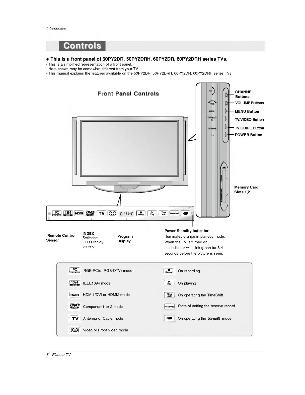
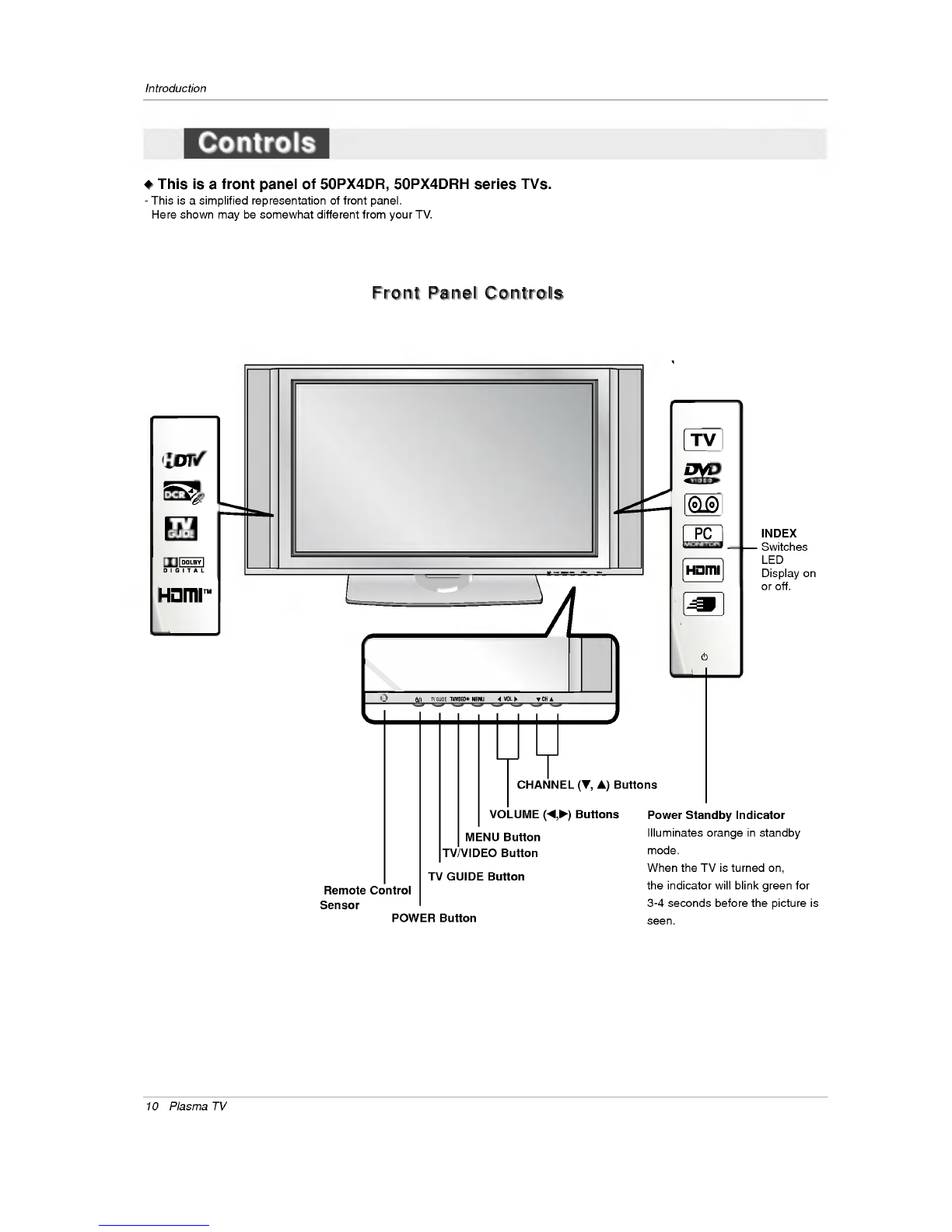
Introduction
Controls/Connection
Options
. . . . . . . . . . . .
.8~11
RemoteControlKeyFunctions.
. . . . . . . .
.12~13
Installation
Accessories...........................14
Installation
Instructions
Joining
the
TV
assembly
to
the
wall
to
protect
the
set
tum-
bling.................................14
Install
the
RING
SPACER
with
the
bolts
on
the
set
asshown.............................15
Remove
orAttachethePlateCover
. . . . . . . . . .
.17
Swivelfunction.........................18
Arrangementwires......................18
External
Equipment
Connections
. . . . . . . . .
.19~25
AntennaorCableConnection
. . . . . . . . . .
.19~20
VCRSetup...........................20
ExternalA/VSourceSetup................21
DVDSetup............................21
CableCARD
TM
Setup.....................22
HDSTBSetup.........................22
PCSetup..........................23~24
MonitorOutSetup......................25
DigitalAudioOutput.....................25
HDMI...............................26~28
TVGuideOnScreenSetup..............29~35
Operation
TurningtheTVOn........................36
HOMEMenu............................37
TVSetup............................38~56
On-screen
Menus
Language
Selection
. . . . . .
.38
Setup
Menu
Options
EZScan(ChannelSearch)................39
ManualScan..........................39
ChannelEdit...........................40
DTVSignalStrength.....................40
ChannelLabelSetup....................41
MainPictureSourceSelection
..... .... ...
.41
InputLabel............................41
Video
Menu
Options
EZPicture............................42
Manual
Picture
Control
(Custom
Option)
. . . . .
.42
ColorTemperatureControl................42
VideoReset...........................42
Audio
Menu
Options
AudioLanguage........................43
EZSoundRite/EZSound.................43
Manual
Sound
Control
(custom
Option)
. . . . . .
.44
FrontSurround.........................44
TVSpeakersOn/OffSetup................45
Stereo/SAPBroadcastsSetup
..... .... ...
.45
BBE.................................45
Time
Menu
Options
AutoClockSetup.......................46
ManualClockSetup.....................46
On/OffTimerSetup.....................46
SleepTimer/AutoOff....................47
Option
Menu
Features
Advanced.............................48
Cinema3:2ModeSetup................48
LowPower..........................48
LGLogo............................49
AspectRatioControl.....................50
Caption...............................51
Caption/Text..........................51
CaptionOption........................52
ISMMethod...........................53
FrontDisplay..........................53
AutoDemo............................54
Lock
Menu
Options
ParentalLockSetup.....................56
CableCARD
TM
Function
Cablemenuoptions.....................57
Scrambledchannel......................57
CableChannelList......................58
EmergencyAlertMessage................58
RecordedTV.......................59~63
NotesonMemoryCard................64~67
PhotoList..........................68~69
MusicList..........................70~72
Timeshift...........................73~74
Recording..........................75~77
TV
Guide
On
Screen
TM
System...........78~98
IEEE1394..........................99~110
Remote
Control
PIP
(Picture-in-Picture)/POP/Twin
Picture
Watching
PIP/POP/Twin
Picture
. . . . . . . . . .
..111
Selecting
an
Input
Signal
Source
for
PIP/Twin
Picture
.111
SwappingPIP/TwinPicture...............111
TVProgramSelectionforPIP
..... ..... ..
.111
MovingthePIPsubpicture...............112
Adjusting
Main
and
Sub
Picture
Sizes
for
Twin
Picture
.112
POP
(Picture-out-of-Picture:
Channel
Scan)
.
.112
APM.
.................................113
BriedInfo...............................114
EZMute...............................115
ScreenSetupforPCmode.................116
ExternalControlDeviceSetup
...... ..... ..
.117~122
IRCodes..............................123~124
ProgrammingtheRemote.....................125
ProgrammingCodes.....................126~127
TroubleshootingChecklist.....................128
Maintenance................................129
ProductSpecifications........................130
Warranty...............................131~132
Contents
Contents

Owner's
Manual
7
Introduction
Introduction
Introduction
What
is
a
Plasma
Display
Panel
(PDP)?
A
plasma
display
panel
is
the
latest
display
technology
and
the
best
way
to
achieve
flat
panel
displays
with
excellent
image
quality
and
large
screen
sizes
that
are
easily
viewable.
The
PDP
can
be
thought
of
as
a
descendant
of
the
neon
lamp
and
it
can
be
also
be viewed
as
a
series
of
fluorescent
lamps.
How
does
it
work?
PDP
is
an
array
of
cells,
known
as
pixels,
which
are
comprised
of
3
sub
pixels,
corresponding
to
the
colors
red,
green,
and
blue.
Gas
in
a
plasma
state
is
used
to
react
with
phosphors
in
each
sub-pixel
to
produce
colored
light
(red,
green,
or
blue).
These
phos-
phors
are
the
same
types
used
in
Cathode
Ray
Tube
(CRT)
devices
such
as
televisions
and
common
computer
monitors.
You
get
the
rich,
dynamic
colors
that
you
expect.
Each
sub-pixel
is
individually
controlled
by
advanced
electronics to
produce
over
16
million
different
colors.
All
of
these
mean
that
you
get
perfect
images
that
are
easily
viewable
in
a
display
that
is
less
than
5
inches
thick.
160°
-
Wide
angle
range
of
vision
Your
flat
panel
plasma
screen
offers
an
exceptionally
broad
viewing
angle
--
over
160
degrees.
This
means
that
the
display
is
clear
and
visible
to
viewers
anywhere
in
the
room
who
can
see
the
screen.
Wide
Screen
The
screen
of
the
Plasma
Display
is
so
wide
that
your
viewing
experience
is
as
if
you
are
in
a
theater.
Multimedia
Connect
your
plasma
display
to
a
PC
and
you
can use
it
for
conferencing,
games,
and
Internet
browsing.
The
Picture-in-Picture
feature
allows
you
to
view
your
PC
and
video
images
simultaneously.
Versatile
The
light
weight
and
thin
size
makes
it
easy
to
install
your
plasma
display
in
a
variety
of
locations
where
conventional
TVs
will
not
fit.
The
PDP
Manufacturing
Process:
a
few
minute
colored
dots
may
be
present
on
the
PDP
screen
The
PDP
(Plasma
Display
Panel),
which
is
the
display
device
of
this
product,
is
composed
of
0.9
to
2.2
million
cells.
A
few
cell
defects
will
normally
occur
in
the
PDP
manufacturing
process.
Several
tiny,
minute
colored
dots
visible
on
the
screen
should
be
acceptable.
This
also
occurs
in
other
PDP
manufacturers'
products.
The
tiny
dots
appearing
does
not
mean
that
this
PDP
is
defec-
tive.
Thus
a
few
cell
defects
are
not
sufficient
cause
for
the
PDP
to
be
exchanged
or
returned.
Our
production
technology
mini-
mizes
these
cell
defects
during
the
manufacture
and
operation
of
this
product.
Cooling
Fan
Noise
In
the
same
way
that
a
fan
is
used
in
a
PC
computer
to
keep
the
CPU
(Central
Processing
Unit)
cool,
the
PDP
is
equipped
with
cooling
fans
to
cool
the
Monitor
and
improve
its
reliability.
Therefore,
a
certain
level
of
noise could
occur
while
the
fans
are
operat-
ing
and
cooling
the
PDP.
The
fan
noise
doesn't
have
any
negative
effect
on
the
PDP's
efficiency
or
reliability.
The
noise
from
these
fans
is
normal
during
the
operation
of
this
product.
We
hope
you
understand
that
a
certain
level
of
noise
from
the
cooling
fans
is
acceptable
and
is
not
suffi-
cient
cause
for
the
PDP
to
be
exchanged
or
returned.

8
Plasma
TV
Introduction
W
W
This
is
a
front
panel
of
50PY2DR,
50PY2DRH,
60PY2DR,
60PY2DRH
series
TVs.
-
This
is
a
simplified
representation
of
a
front
panel.
Here
shown
may
be
somewhat
different
from your
TV.
-
This
manual
explains
the
features
available
on
the
50PY2DR,
50PY2DRH,
60PY2DR,
60PY2DRH
series
TVs.
Front
Panel
Controls
Front
Panel
Controls
MENU
Button
TV/VIDEO
Button
POWER
Button
VOLUME
Buttons
CHANNEL
Buttons
INDEX
Switches
LED
Display
on
or
off.
TV
GUIDE
Button
Remote
Control
Sensor
Power
Standby
Indicator
Illuminates
orange
in
standby
mode.
When
the
TV
is
turned
on,
the
indicator
will
blink
green
for
3-4
seconds
before
the
picture
is
seen.
Controls
Controls
Memory
Card
Slots
1,2
Program
Display
RGB-PC(or
RGB-DTV)
mode
IEEE1394
mode
HDMI1/DVI
or
HDMI2 mode
Component1
or
2
mode
Antenna
or
Cable
mode
Video
or
Front
Video
mode
On
recording
On
playing
On
operating
the
TimeShift
State
of
setting
the
reserve
record
On
operating
the
mode

RS
32CINPUT
CONTROL/SERVCE)
AUDOINPUT
CMPNN
2
R
L
GTAAUDO(OTCAL)
DVI
NPUT
OMOET
INPUT
OUTPUT
AUDONPUT
RGBINPUT
VIDEO
NPUT
I
E
E
1
3
4
HDMI2
HDMI/DVI
CMPNN
1
MNOR
OTUT
AV
PT1
VDEO
R
LUI
MNO)
V
I
D
S R
E
M
O
C
O
N
T
CABE NTNNA
ACINPUT
DVD
/V
IPUT
S-VIDEO
VIDEO
L/MONO
AUDIO
FRONT
A/V
INPUT
R
RS-232C
INPUT
(CONTROL/SERVICE)
AUDIO
R
L
DIGITAL
AUDIO
(OPTICAL)
DVI
INPUT
COMPONENT2
INPUT
OUTPUT
AUDIO
INPUT
RGB
INPUT
VIDEO
HDMI
2
HDMI
/DVI
COMPONENT
INPUT
1
R
L
(MONO)
CABLE
ANTENNA
AC
INPUT
DVD
/DTV
INPUT
IEEE-1394
COMPONENT
INPUT 2
MONITOR
OUTPUT
A/V
INPUT
1
VIDEO
AUDIO
S-VIDEO
REMOTE
CONTROL
Cable
Owner's
Manual
9
Introduction
Back
Connection
Panel
Back
Connection
Panel
Antenna
Input
Connect
over-the-
air
signals
to
this
jack.
RGB/AUDIO
INPUT
Connect
the
moni-
tor
output
from
a
PC
to
the
appropri-
ate
input
port.
Digital
Audio
(DVI:
Digital
Visual
Interface/Compon
ent2)
Input/
Digital
Audio
Output
Connect
digital
audio
from
various
types
of
equipment.
Note:
In
standby
mode,
these
ports
will
not
work.
DVD/DTV
Input
(Component
1-2)
Connect
a
com-
ponent
video/audio
device
to
these
jacks.
Monitor
Output
Connect
a
second
TV
or
Monitor.
Remote
Control
Port
Connect
your
wired
remote
control
here.
S-Video
Input
Connect
S-
Video
out
from
an
S-VIDEO
device.
CABLE
Input
Connect
cable
signals
to
this
jack,
either
directly
or
through
a
cable
box.
RS-232C
INPUT
(CONTROL/SER-
VICE)
PORT
Connect
to
the
RS-
232C
port
on a
PC.
HDMI1/DVI(VIDE
O),
HDMI
2
Connect
a
HDMI
signal
to
HDMI1/DVI
or
HDMI2.
Or
DVI(VIDEO)
sig-
nal
to
HDMI1/DVI
port
with
DVI
to
HDMI
cable.
VIDEO
Input
Connects
the
video
signal
from
a
video
device.
AUDIO
Input
Connections
are
available
for
listen-
ing
stereo
sound
from
an
external
device.
Audio/Video
Input
Connect
audio/video
output
from
an
exter-
nal
device
to
these
jacks.
Power
Cord
Socket
This
TV
operates
on
an
AC
power.
The
voltage
is
indicated
on
the
Specifications
page.
Never
attempt
to
operate
the
TV
on
DC
power.
CableCARDTM
Used
for
CableCARDTM
received
Cable
Service
Provider.
G-LINK
Connect
an
IR
controller
to
this
jack.
IEEE1394
Connect
DVHS
or
MicroMV
to
IEEE1394
Connector.
Connection
Options
Connection
Options
Note:
-
After
removing
the
cover,
you
can
insert
the
CableCARDTM
or
connect
to
the
G-LINK
jack.
W
W
This
is
a
back
panel
of
50PY2DR,
50PY2DRH,
60PY2DR,
60PY2DRH
series
TVs.
S-VIDEO
Input
A
connection
is
available
to
provide
better
picture
quality
than
the
video
input.

10
Plasma
TV
Introduction
TV
GUIDE
TV
GUIDE
MENU
Button
TV/VIDEO
Button
VOLUME
(F,G)
Buttons
CHANNEL
(E,
D)
Buttons
INDEX
Switches
LED
Display
on
or
off.
TV
GUIDE
Button
Remote
Control
Sensor
Power
Standby
Indicator
Illuminates
orange
in
standby
mode.
When
the
TV
is
turned
on,
the
indicator
will
blink
green
for
3-4
seconds
before
the
picture
is
seen.
POWER
Button
Front
Panel
Controls
Front
Panel
Controls
W
W
This
is
a
front
panel
of
50PX4DR,
50PX4DRH
series
TVs.
-
This
is
a
simplified
representation
of
front
panel.
Here
shown
may
be
somewhat
different
from your
TV.
Controls
Controls

Owner's
Manual
11
Introduction
Connection
Options
Connection
Options
W
W
This
is
a
back
panel
of
50PX4DR,
50PX4DRH
series
TVs.
RS-232C
INPUT
(CONTROL/SERVICE)
AUDIO
R
L
DIGITAL
AUDIO
(OPTICAL)
DVI
INPUT
COMPONENT2
INPUT
OUTPUT
AUDIO
INPUT
RGB
INPUT
VIDEO
HDMI
2
HDMI1/DVI
COMPONENT
INPUT
1
R
L
(MONO)
CABLE
ANTENNA
AC
INPUT
DVD
/DTV
INPUT
IEEE-1394
COMPONENT
INPUT
2
MONITOR
OUTPUT
A/V
INPUT
VIDEO
AUDIO
S-VIDEO
REMOTE
CONTROL
S-VIDEO
FRONT
A/V
INPUT
VIDEO
L/MONO
AUDIO
R
Cable
S-VIDEO
Input
A
connection
is
available
to
provide
better
picture
quality
than
the
video
input.
Memory
Card
Slots
G-LINK
TM
Connect
an
IR
controller
to
this
jack.
CableCARDTM
Used
for
CableCARDTM
received
from
Cable
Service
Provider.
VIDEO
Input
Connects
the
video
signal
from
a
video
device.
AUDIO
Input
Connections
are
available
for
listening
stereo
sound
from
an
external
device.
Antenna
Input
Connect
over-the-
air
signals
to
this
jack.
RGB/AUDIO
INPUT
Connect
the
monitor
output
connector
from
a
PC
to
the
appropriate
input
port.
Digital
Audio
(DVI:
Digital
Visual
Interface/Component2)
Input/
Digital
Audio
Output
Connect
digital
audio
from
various
types
of
equipment.
Note:
In
standby
mode,
these
ports
will
not
work.
DVD/DTV
Input
(Component
1-2)
Connect
a
component
video/audio
device
to
these
jacks.
Monitor
Output
Connect
a
second
TV
or
Monitor.
Remote
Control
Port
Connect
your
wired
remote
control
here.
S-Video
Input
Connect
S-
Video out from
an
S-VIDEO
device
to
the
S-
VIDEO
input.
CABLE
Input
Connect
cable
signals
to
this
jack,
either
directly
or
through
a
cable
box.
RS-232C
INPUT
(CON-
TROL/SERVICE)
PORT
Connect
to
the
RS-232C
port
on
a
PC.
HDMI1/DVI,
HDMI
2
Connect
a
HDMI
sig-
nal
to
HDMI1/DVI
or
HDMI2.
Or
connect
a
DVI(Video)
signal
to
HDMI1/DVI.
Audio/Video
Input
Connect
audio/video
output
from
an
external
device
to
these
jacks.
Power
Cord
Socket
This
TV
operates
on
an
AC
power.
The
voltage
is
indicated
on
the
Specifications
page.
Never
attempt
to
operate
the
TV
on
DC
power.
IEEE1394
Connect
DVHS
or
MicroMV
to
IEEE1394
Connector.
Back
Connection
Panel
Back
Connection
Panel

12
Plasma
TV
Introduction
-
When
using
the
remote
control,
aim
it
at
the
remote
control
sensor
on
the
TV.
MODE
D
A
Y
-
D
A
Y
+
FLASHBK
APM
CC
AUTO
DEMO
M/C
EJECT
TV
INPUT
TV/VIDEO
LIGHT
Illuminates
the
remote
control
buttons
of
selected
mode.
DAY+/DAY-
Moves
the
Listings
Grid
forward
or
backward
in
24
hour
increments.
NUMBER
buttons
/VCR/DVD
control
buttons
?
Use
for
DVR
record
or
trick
play.
? ?
?
(Refer
to
p.61,
74)
?
Use
for
Photo
mode
or
Music
mode
?of
.
(Refer
to
p.69,
72)
?
Controls the
DVHS
or
Camcorder
in
?
IEEE
1394
mode.
?
Controls
some
video
cassette
? ? ? ?
?
recorders
or
DVD
players
when
you
?
have
already
selected
DVD
or
VCR
?
mode
button.
RATIO
Changes
the
aspect
ratio.
POWER
Turns
your
TV
or
any
other
programmed
equipment
on
or
off,
depending
on
mode.
CC
Select
a
closed
caption:
Off,
CC1~4,
Text1~4.
THUMBSTICK
(Up/Down/Left/Right/ENTER)
Allows
you
to
navigate
the
on-screen
menus
and
adjust
the
system
settings
to
your
pref-
erence.
CHANNEL
UP/DOWN
Selects
available
channels
found
dur-
ing
Manual
scan.
PAGE
UP/PAGE
DOWN
Moves
from
one
full
set
of
screen
information
to
the
next
one.
SAP
Selects
MTS
sound:
Mono,
Stereo,
and
SAP
in
Analog
mode.
Change
the
audio
language
in
DTV
mode.
EZ
SOUND
Selects
the
sound
appropriate
for
the
program's
character.
Bring
up
the
HOME
menu
to
the
screen.
APM
(Adaptive
Picture
Mode)
Concurrently,
compare
with
the
Daylight,
Normal,
Night
Time
and
Custom
on
the
screen.
(Refer
to
p.113)
VOLUME
UP/DOWN
Increases/decreases
the
sound
level.
REC
LIST
Appear
the
thumbnail
recorded
list.
M/C
EJECT
Remove
the
Memory
Card.
Remote
Control
Key
Functions
Remote
Control
Key
Functions
FLASHBK
Tunes
to
the
last
channel
viewed.

Owner's
Manual
13
Introduction
MODE
D
A
Y
-
D
A
Y
+
FLASHBK
APM
CC
AUTO
DEMO
M/C
EJECT
T
INPUT
TV/VIDEO
TV
INPUT
?
Rotates
the
input
mode
between Antenna
and
Cable.
?
Video,
Front
Video,
Component
1-2,
RGB-
DTV
(or
RGB-PC),
HDMI1/DVI,
HDMI2
and
IEEE1394
input
sources,
screen
returns
to
the
last
TV.
MUTE
Switches
the
sound
on
or
off.(Refer
to
p.115)
MODE
Selects
the
remote
operating
mode:
TV,
DVD,
VCR,
AUDIO,
CABLE
or
STB.
Select
other
operating
modes,
for
the
remote
to
operate
external
devices.
EXIT
Clears
all
on-screen
displays
and
returns
to
TV
viewing
from
any
menu.
TIMER
Lets
you
select
the
amount
of
time
before
your
TV
turns
itself
off
automatically.
MENU
Brings
up
the
main
menu
to
the
screen.
Enters
or
exits
a
Panel
Menu
in
the
TV
Guide
On
Screen
system.
PIP
Switches
to
PIP,
POP
(Picture-out-of-
Picture)
and
Twin
picture
modes
in
regu-
lar
sequence.
Switches
the
video
window
locking
or
unlocking
in
the
Listings
Grid.
PIPCH-/PIPCH+
Changes
to
the
next
higher/lower
PIP
channel.
PIP
INPUT
Selects
the
input
source
for
the
sub
pic-
ture
in
PIP/Twin
picture
mode.
SWAP
Exchanges
the
main/sub
images
in
PIP/Twin
picture
mode.
EZ
PIC
Adjusts
the
factory
preset
picture
depending
on
the
viewing
environment.
ADJUST
Adjusts
screen
position,
size,
and
phase
in
PC
mode.
AUTO
DEMO
Starts
the
demonstration
to
explain
the
main
features
of
this
TV.
TV/VIDEO
External
input
modes
rotate
in
regular
sequence:
Antenna,
Cable,
Video,
Front
Video,
Component
1-2,
RGB-DTV
(or
RGB-PC),
HDMI1/DVI
and
HDMI2
input
sources.
(Video,
Front
Video,
Component
1-2
input
sources
are
linked
automatically,
only
if
these
are
connected
)
INFO
When
you
watch
the
TV,
information
dis-
plays
on
top
of
the
screen.
Not
available
in
Component
1-2,
RGB,
HDMI1/DVI
and
HDMI2
mode.(Refer
to
p.114)
FAV
Scrolls
the
Favorite
channels.
TV
GUIDE
Brings
up
the
TV
Guide
On
Screen
sys-
tem
to
the
screen.
Mark
Selects
the
wanted
functions.
?
Open
the
battery
compartment
cover
on
the
back
side
and
install
the
batteries
matching
correct
polarity
(+
with
+,
-
with
-).
?
Install
two
1.5V
AA
batteries.
Don't
mix
old
or
used
batteries
with
new
ones.
Close
cover.
Installing
Batteries
Installing
Batteries

14
Plasma
TV
Installation
Installation
Installation
Owner's
Manual
1.5V
1
.
5
V
Batteries
Power
Cord
75Ω
Round
Cable
Ensure
that
the
following
accessories
are
included
with
your
TV.
If
any
accessory
is
missing,
please
contact
the
dealer
from
where
you
purchased
the
product.
User
must
use
shielded
signal
interface
cables(D-sub
15
pin
cable)
with
ferrite
cores
to
maintain
standard
compli-
ance
for
the
product.
Remote
Control
Installation
Instructions
Installation
Instructions
Accessories
Accessories
-
Secure
the
TV
assembly
by
joining
it
to
a
wall
by
using
the
TV/Wall
brackets.
-
Here
shown
may
be
somewhat
different
from
your
TV.
Joining
the
Joining
the
TV
assembly
to
the
wall
to
protect
the
set
tumbling
TV
assembly
to
the
wall
to
protect
the
set
tumbling
2-Wall
brackets(60")
2-TV
brackets(60")
G-LINK
Cable
6-RING
SPACER
(Only
60PY2DR/60PY2DRH
series)
6-
bolts
(Only
60PY2DR/60PY2DRH
series)
2-Wall
brackets(50")
2-eye-bolts(50")
50PY2DR/50PY2DRH
?
If
the
set
will
be
mounted
on
a
desk
top,
insert
the
2
eye-bolts
and
tighten
them
securely
in
the
upper
holes
as
shown.
Install
the
wall
brackets
on
the
wall
with
2
bolts*,
(not
supplied
with
the
product),
as
shown.
Match
the
height
of
the
eye-bolts
and
the
wall
brack-
ets.
Check
to
be
sure
the
eye-bolts
and
the
brackets
are
tightened
securely.
Option
Extras
D-sub
15
pin
cable

Owner's
Manual
15
Installation
?
Secure
the
TV
assembly
to
the
wall
with
strong
strings
or
wire
cables,
(not
supplied
with
the
prod-
uct),
as
shown.
?
If
the
set
will
be
mounted
on a
desk
top,
install
the
2
ring
spac-
er
on
the
TV.
And
then
install
the
TV
brackets
on
the
ring
spacer
as
shown.
Insert
the
2
bolts
and
tighten
securely,
in
the
upper
holes
on
the
brackets.
Install
the
wall
brackets
on
the
wall
with
2
bolts*,
(not
sup-
plied
with
the
product).
Match
the
height
of
the
TV
brackets
and
the
wall
brackets.
Check
to
be
sure
the
brackets
are
tightened
securely.
Note:
Bolts
and
RING
SPACER
commonly
use
for
fixing
the
TV
bracket
or
connecting
the
wall
mounting
bracket.
50PX4DR/50PX4DRH
2.
When
you
connect
the
wall
mounting
bracket
to
the
set,
connect
to
it
by
using
the
6-bolts,
(supplied
with
the
product),
as
shown.
Install
the
RING
SP
Install
the
RING
SP
ACER
with
the
bolts
on
the
set
as
shown.
ACER
with
the
bolts
on
the
set
as
shown.(Only
60PY2DR/60PY2DRH
series
)
?
If
the
set
will
be
mounted
on
a
desk
top,
insert
the
2
eye-bolts
and
tighten
them
securely
in
the
upper
holes
as
shown.
Install
the
wall
brackets
on
the
wall
with
2
bolts*,
(not
supplied
with
the
product),
as
shown.
Match
the
height
of
the
eye-bolts
and
the
wall
brack-
ets.
Check
to
be
sure
the
eye-bolts
and
the
brackets
are
tightened
securely.
1.
Put
the
RING
SPACER
in
the
holes
of
the
bolts
before
connecting
to
the
wall
mounting
bracket.
Note:
Bolts
and
RING
SPACER
commonly
use
for
fixing
the
TV
bracket
or
connecting
the
wall
mounting
bracket.
60PY2DR/60PY2DRH

16
Plasma
TV
Installation
Installation
Instructions
Installation
Instructions
GROUNDING
Ensure
that
you
connect
the
earth
ground
wire
to
prevent
possible
electric
shock.
If
grounding
methods
are
not
possible,
have
a
qualified
electrician
install
a
separate
circuit
breaker.
Do
not
try
to
ground
the
unit
by
connecting
it
to
telephone
wires,
lightening
rods,
or
gas
pipes.
TVGUDE
Power
Supply
Short-circuit
Breaker
4
inches
4
inches
2.36 inches
4
inches
2
inches
Desktop
Pedestal
Installation
Desktop
Pedestal
Installation
For proper
ventilation,
allow
a
clearance
of
4"
on
each
side
and
the
top,
2.36"
on
the
bottom,
and
2"
from
the
wall.
Detailed
installation
instructions
are
included
in
the
optional
Desktop
Stand
Installation.
?
The
TV
can
be
installed
in
various
ways
such
as
on a
desktop
etc.
?
The
TV
is
designed
to
be
mounted
horizontally.
?
It
is
recommended
that
50PY2DR,
60PY2DR,
50PX4DR
model
only
be
used
at
an
altitude
of
less
than
3281
feet
(1000m)
to
get
the
best
quality
picture
and
sound.
?
It
is
recommended
that
50PY2DRH,
60PY2DRH,
50PX4DRH
model
only
be
used
at
an
altitude
of
less
than
6561
feet
(2000m)
to
get
the
best
quality
picture
and
sound.
-
This
manual
explains
the
features
available
on
the
50PY2DR,
50PY2DRH,
60PY2DR,
60PY2DRH
series
TVs.
-
Here
shown
may
be
somewhat
different
from your
TV.
To
Install
on
a
Desktop
Pedestal
mount
minimum
allowableclearances
for
adequate
ventilation.

Owner's
Manual
17
Installation
RS
32C
NPUT
(CONROLSERVCE)
AUDO
NPUT
OPNN
2
R
L
DGTLAUIO
OPCAL)
DVI
NPUT
OMNN2
INPUT
UTUT
AUDOINPUT
RGBINPUT
VIDEOINPUT
I
E
E
1
3
9
HDM2
HDMI
DVI
OPNN
1
MOTR
UPT
V
NU1
IDO R
LUO
MN)
I
D
E
S R
E
M
O
T
E
C
O
N
T
R
O
L
CABE ATENA AC
NPUT
DVD
DTV
NPT
Remove
or
Remove
or
Attache
the
Plate
Cover
Attache
the
Plate
Cover
(Only
50/60PY2DR,
50/60PY2DRH
series
)
2.
Connect
the
power
cord
on
the
TV's
back.
-
This
function
explains
the
features
available
on
the
50PY2DR,
50PY2DRH,
60PY2DR,
60PY2DRH
series
TVs.
?
When
moving
or
connecting
the
power
cord,
be
used
the
these
methods.
?
And
after
removing
the
plate
cover,
you
must
install
the
wall
brackets
on
the
wall.
1.
With
hands,
push
the
lower
left/right
of
plate
cover
and
then
pull
out
to
the
front.
3.
In
attaching
the
plate
cover,
align
the
guide
to
the
bush-
ings
and
press
the
cover
in
place
with
your
hand.

18
Plasma
TV
Installation
RS
32C
NPUT
CONTOLSERIC) AUDIONPUT
OPNN
2
RL
DGTLADO(PTCAL)
DVI
NPT
OPNN2
IPUT
OUPU
AUDONPUTRGBNPUT
VDEOINPUT
I
E
E
1
3
9
HDMI2
HDM/DVI
OPNN
1
MNOR
OTUT
AV
PT1
VDEO
R
LD
MO)
V
D
E
S R
E
M
O
T
E
C
O
N
TR
O
CBLEATNNA AC
NPUT
DD
DTV
NPT
Swivel
function
Swivel
function
-
This
function
explains
the
features
available
on
the
50/60PY2DR,
50/60PY2DRH
series
TVs.
?
After
installing
the
TV,
you
can
adjust
the
the
TV
set
manually
turning
it
to
the
left
or
right
direction
by
20
degrees
to
suit
your
viewing
position.
Arrangement
wires
Arrangement
wires
(Only
50/60PY2DR,
50/60PY2DRH
series
)
-
This
function
explains
the
features
available
on
the
50/60PY2DR,
50/60PY2DRH
series
TVs.
?
Run
the
accessory
device
wires
inside
the
JACK
MANAGEMENT
pole
as
shown.
Note:
Before
adjusting
the
angle,
you
must
loosen
(to
the
left)
the
shaft
bolt
on
the
middle
of
stand's
back.
And
when
you
acheve
the
desired
position,
you
must
close
the
shaft
bolt
to
set
the
hole.(As
shown
below)
20°
Installation
Instructions
Installation
Instructions
50/60PY2DR,
50/60PY2DRH
50PX4DR/50PX4DRH
20°

Owner's
Manual
19
Installation
Antenna
or
Cable
Connection
Antenna
or
Cable
Connection
-
Wall
Antenna
Socket
or
Outdoor
Antenna
without
a
Cable
Box
Connections
-
For
optimum
picture
quality,
adjust
antenna
direction
if
needed.
1.
Analog
and
Digital
TV
signals
provided
on
antenna
2.
Analog
and
Digital
TV
signals
provided
on
cable
CABLE
ANTENNA
AC
INPUT
Multi-family
Dwellings/Apartments
(Connect
to
wall
antenna
socket)
Single-family
Dwellings
/Houses
(Connect
to
wall
jack
for
outdoor
antenna)
Outdoor
Antenna
Wall
Antenna
Socket
VHF
Antenna
UHF
Antenna
RF
Coaxial
Wire
(75
ohm)
Bronze
Wire
Turn
clockwise
to
tighten.
Bronze
Wire
Be
careful
not
to
bend
the
bronze
wire
when
connecting
the
antenna.
Bronze
Wire
Cable
TV
Wall
Jack
RF
Coaxial
Wire
(75
ohm)
CABLE
ANTENNA
AC
INPUT
External
Equipment
Connections
External
Equipment
Connections
Turn
clockwise
to
tighten.

20
Plasma
TV
Installation
-
To
avoid
picture
noise
(interference),
leave
an
adequate
distance
between
the
VCR
and
TV
-
Use
the
ISM
Method
(on
the
Option
menu)
feature
to
avoid
having
a
fixed
image
remain
on
the
screen
for
a
long
period
of
time.
If
the
4:3
picture
format
is
used;
the
fixed
images
on
the
sides
of
the
screen
may
remain
visible
on
the
screen.
Connection
Option
1
Set
VCR
output
switch
to
3
or
4
and
then
tune
TV
to
the
same
channel
number.
Connection
Option
2
1.
Connect
the
audio
and
video
cables
from
the
VCR's
output
jacks
to
the
TV
input
jacks,
as
shown
in
the
figure.
When
connecting
the
TV
to
VCR,
match
the
jack
colors
(Video
=
yellow,
Audio
Left
=
white,
and
Audio
Right
=
red).
If
you
connect
an
S-VIDEO
output
from
VCR
to
the
S-VIDEO
input,
the
picture
quality
is
improved;
compared
to
connecting
a
regular
VCR
to
the
Video
input.
2.
Insert
a
video
tape
into
the
VCR
and
press
PLAY
on
the
VCR.
(Refer
to
the
VCR
owner
's
manual.)
3.
Select
the
input
source
with
using
the
TV/VIDEO
button
on
the
remote
control.
(If
connected
to
A/V
INPUT
,
select
Video
input
source)
Do
not
connect
to
both
Video
and
S-Video
at
the
same
time.
VCR
Setup
VCR
Setup
AUDIO
R
L
RGB
INPUT
VIDEO
COMPONENT
INPUT
1
R
L
(MONO)
CABLE
ANTENNA
AC
INPUT
DVD
/DTV
INPUT
COMPONENT
INPUT
2
MONITOR
OUTPUT
A/V
INPUT
VIDEO
AUDIO
AUDIO
INPUT
S-V
O
REMOTE
CONTROL
S-VIDEO
OUT
IN
(R)
AUDIO
(L)
VIDEO
34
OUTPUT
SWITCH
ANT
OUT
ANT
IN
VCR
Rear
1
Note:
The
TV
will
let
you
know
when
the
analog,
cable,
and
digital
channel
scans
are
complete.
?
To
improve
the
picture
quality
in
a
poor
signal
area,
please
purchase
a
signal
amplifier
and
install
properly.
?
If
the
antenna
needs
to
be
split
for
two
TV's,
install
a
"2-
Way
Signal
Splitter"
in
the
connections.
?
If
the
antenna
is
not
installed
properly,
contact
your
deal-
er
for
assistance.
ANTENNA
Signal
Amplifier
3.
Analog
and
Digital
TV
signals
provided
on
cable
and
antenna
Antenna
RF
Coaxial
Wire
(75
ohm)
Bronze
Wire
Turn
clockwise
to
tighten.
Cable
TV
Wall
Jack
RF
Coaxial
Wire
(75
ohm)
CABLE
ANTENNA
AC
INPUT
2
Bronze
Wire
Other manuals for 50PY2DR
5
This manual suits for next models
11
Table of contents
Other LG Plasma TV manuals
Popular Plasma TV manuals by other brands

Panasonic
Panasonic Viera TH-P55ST30A operating instructions

Philips
Philips 42 IN PLASMA FLAT TV HDTV MONITOR 42FD9954 Specifications

Samsung
Samsung PS51E6505 user manual

Optoma
Optoma SP50A Specification sheet

Panasonic
Panasonic Viera TC-P50U50 owner's manual

Panasonic
Panasonic TC-P42C1 - 41.6" Plasma TV operating instructions