LG 60PT1RF User manual

Please read this manual carefully before operating
your set.
Retain it for future reference.
Record model number and serial number of the set.
See the label attached on the back cover and quote
this information to your dealer when you require
service.
PLASMA TV
OWNER’S MANUAL
PLASMA TV MODELS
6600PPTTRRFF**
PP//NNOO:: MMFFLL33774455777755 ((00770099--RREEVV0000))
PPrriinntteedd iinn KKoorreeaa


1
ACCESSORIES
Ensure that the following accessories are included with your TV. If an accessory is missing, please contact the
dealer where you purchased the product.
ACCESSORIES
Owner’s Manual Batteries
Remote Control
Power Cord
Polishing Cloth
Polish the screen with the cloth
*Slightly wipe stained spot on the
exterior only with the cleansing
cloths or the product exterior i
there is stain or ingerprint on sur ace
o the exterior.
Do not wipe roughly when removing
stain. Please be cautious o that
excessive power may cause scratch
or discoloration.
Holder
(Re er to p.7)
Optional e tras can be changed or modified for quality improvement without any notification new option-
al e tras can be added.
Contract your dealer for buying these items.
Option Extras
Option Extras
Tilt wall mounting bracket
Desktop stand
Owner's
Manual
VOLPR
123
45
7
OK
INPUTMODE
TV
TV
DVD
RATIO
EXIT
VOL
POSITION
PR
PIP
SLEEP
LIST
Q.VIEW
I/II
MENU
SIZE
VCR
PIP PR-PIPPR+
PIP INPUT
POWER
123
456
789
0
SIMPLINK
INPUT
SWAP
COMP1
RGB
AV1
COMP2
HDMI1/2
AV2
MUTE
BRIGHT
FAV
MUTE
FAV

2
CONTENTS
CONTENTS
PICTURE CONTROL
Watching PIP(Picture-in-Picture) .............................44
Picture Size (Aspect Ratio)Control.........................46
Preset Picture Settings
- Picture Mode-Preset............................................48
- Auto Colour Tone Control(Warm/Medium/Cool)
49
Manual Picture Adjustment
- Picture Mode-User Option................................50
- Colour Tone - User Option ...............................5
-
Picture Improvement Technology
...................52
Advanced - Cinema......................................................53
Advanced - Black(Darkness) Level...........................54
Picture Reset ..................................................................55
Demo .................................................................56
Image Sticking Minimization(ISM) Method...........57
Low-Power Picture Mode............................................58
WATCHING TV /PROGRAMME CONTROL
Remote Control Key Functions.................................28
Turning on the TV....................................................... 30
Programme Selection ................................................. 30
Volume Adjustment......................................................30
On Screen Menus Selection and Adjustment.......3
Auto Programme Tuning............................................ 32
Manual Programme Tuning ....................................... 33
Fine Tuning .....................................................................34
Assigning a Station Name ..........................................35
Booster............................................................................36
Programme Edit ........................................................... 37
Favourite Programme .................................................. 38
Calling the Programme List....................................... 39
Input Source Selection ...............................................40
................................................................. 4
Key lock.......................................................................... 43
PICTURE CONTROL
WATCHING TV / PROGRAMME CONTROL
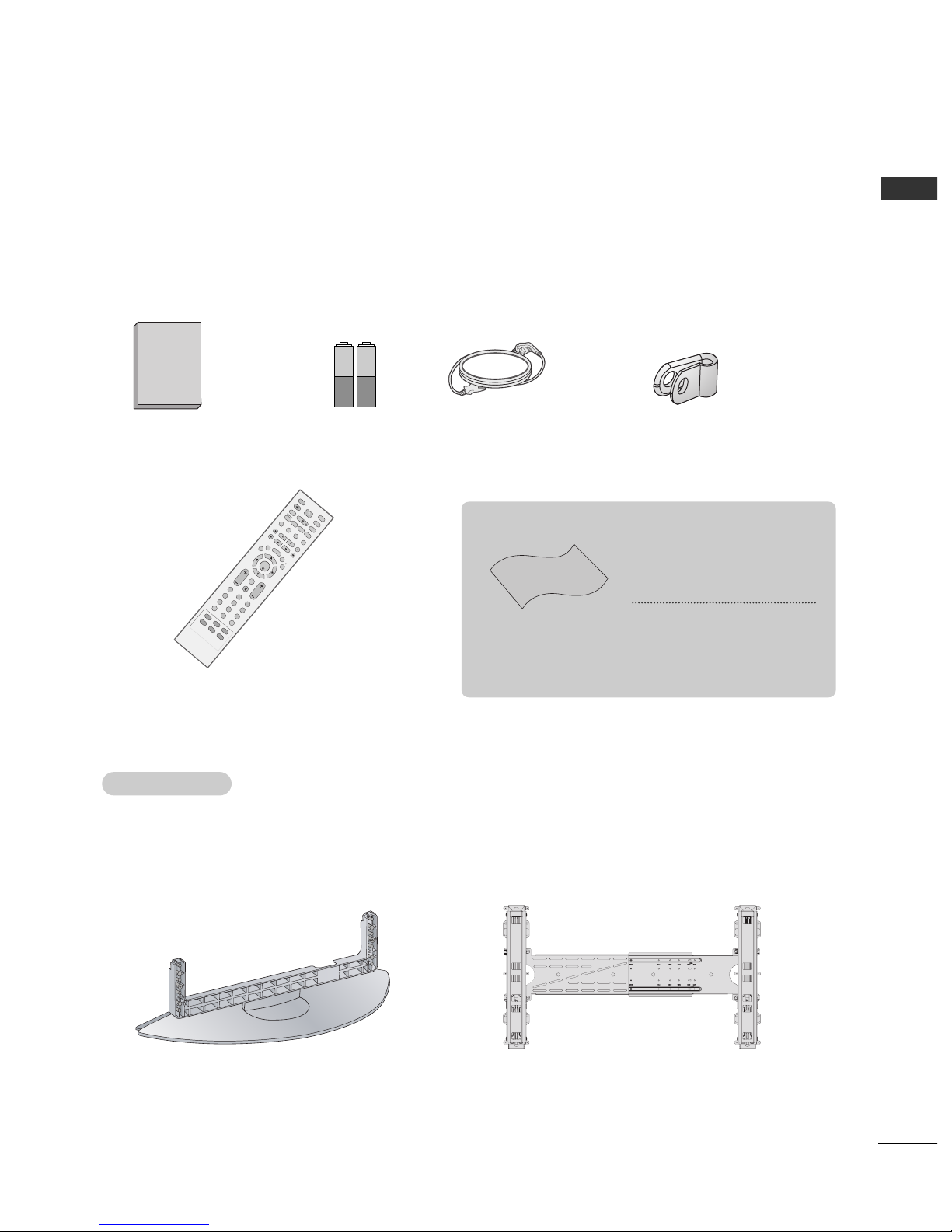
AACCCCEESSSSOORRIIEESS.....................................................
PREPARATION
Front Panel Controls..................................................... 4
Back Panel Information ................................................ 5
Desktop Pedestal Installation..................................... 6
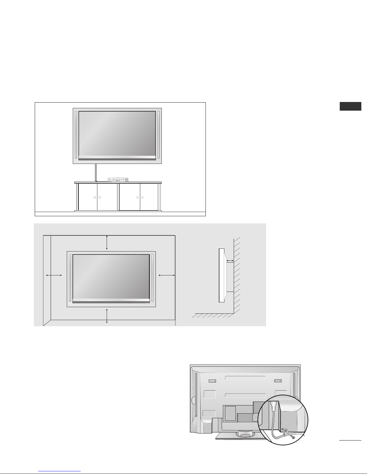
Wall Mount: Horizontal installation .......................... 7
Power cord Arrangement ............................................. 7
Antenna Connection..................................................... 8
EXTERNAL EQUIPMENT SETUP
HD Receiver Setup .........................................................9
DVD Setup ..................................................................... 2
VCR Setup ..................................................................... 5
Other A/V Source Setup........................................... 8
PC Setup ......................................................................... 9
- Screen Setup for PC Mode................................22
AV Output Setup ........................................................ 26
External Stereo Setup ................................................ 27
PREPARATION

3
CONTENTS
SOUND & LANGUAGE CONTROL
Preset Sound Settings - Sound Mode ....................59
Sound Setting Adjustment - User Mode ...............60
Auto Volume Leveler ....................................................6
Balance ............................................................................62
TV Speakers On/Off Setup.......................................63
I/II
- Stereo/Dual Reception.......................................64
- NICAM Reception ................................................65
- Speaker Sound Output Selection....................65
On-Screen Menu Language Selection
...................... 66
APPENDIX
Troubleshooting ............................................................74
Maintenance .................................................................76
Product Specifications ................................................77
Programming the Remote Control ........................ 78
IR Codes .........................................................................80
External Control Through RS-232C........................82
TIME SETTING
Clock Setting..................................................................67
Auto On/Off Timer Setting .......................................68
Sleep Timer Setting......................................................69
Auto Shut-off Setting...................................................70
TELETEXT
Switch On/Off ..............................................................7
SIMPLE Text....................................................................7
TOP Text .........................................................................72
FASTEXT .........................................................................72
Special Teletext Functions..........................................73

4
FRONT PANEL CONTROLS
PREPARATION
PREPARATION
■
This is a simplified representation of the front panel. Here shown may be somewhat different from your TV.
■
The external appearance of the set has an inherent character(annual ring, wood grain, knar) of wood.
■
If your product has a protection film attached, remove the film and then wipe the product with a polishing
cloth.
Power/Standby Indicator
• illuminates red in standby mode.
• illuminates green when the set is switched on.
PR
VOL
OK
MENU
INPUT
Remote Control Sensor
PROGRAMME Buttons
VOLUME Buttons
OK Button
MENU Button
INPUT Button
POWER Button

5
PREPARATION
BACK PANEL INFORMATION
■
This is a simplified representation of the back panel. Here shown may be somewhat different from your TV.
HDMI/DVI1, HDMI2 Input
Connect a HDMI signal to HDMI IN.
Or DVI(VIDEO)signal to HDMI/DVI port with DVI
to HDMI cable.
RGB/Audio Input
Connect the monitor output from a PC to the
appropriate input port.
Audio/Video Input (AV IN 1)
Connect audio/video output from an external
device to these jacks.
AV Output
Connect second TV or monitor to the AV OUT
socket on the set.
Antenna Input
Connect over-the-air signals to this jack.
Component Input 1/2
Connect a component video/audio device to
these jacks.
Variable Audio Output
Connect an external amplifier or add a subwoofer
to your surround sound system.
RS-232C Input(CONTROL&SERVICE)Port
Connect the serial port of the control devices
to the RS-232C jack.
Power Cord Socket
This TV operates on an AC power. The voltage is
indicated on the Specifications page. Never
attempt to operate the TV on DC power.
1
2
3
4
5
6
7
8
9
9
S-Video Input
Connect S-Video out
from an S-VIDEO device.
Audio/Video Input
Connect audio/video
output from an external
device to these jacks.
AV IN 2V IN 2
L/L/MONOMONO
R
AUDIOAUDIO
VIDEOVIDEO
S-VIDEOS-VIDEO
HDMI INHDMI/DVI IN
1
1
2
2
VARIABLE AUDIO OUT
RGB IN
COMPONENT IN
AV IN 1 AV OUT
L/MONO
R
AUDIO
VIDEO
RS-232C IN
(CONTROL&SERVICE)
AV IN 2
L/MONO
R
AUDIO
VIDEO
S-VIDEO
HDMI IN
HDMI IN
HDMI/DVI IN
HDMI/DVI IN
1
1
2
2
VARIABLE
ARIABLE
AUDIO OUT
AUDIO OUT
AUDIO
(RGB/DVI)
RGB
(PC)
RGB IN
RGB IN
COMPONENT IN
COMPONENT IN
AUDIO
VIDEO
AV IN 1
V IN 1
AV OUT
V OUT
L/
L/
MONO
MONO
R
AUDIO
AUDIO
VIDEO
VIDEO
ANTENNA
IN
RS-232C IN
(CONTROL&SERVICE)
2
1
4
35
7
68

6
PREPARATION
■The TV can be installed in various ways such as on a wall, or on a desktop etc.
■The TV is designed to be mounted horizontally.
Power Supply
Short-circuit
Breaker
GROUNDING
Ensure that you connect the earth ground wire to prevent
possible electric shock. If grounding methods are not possi-
ble, have a qualified electrician install a separate circuit
breaker.
Do not try to ground the unit by connecting it to telephone
wires, lightening rods, or gas pipes.
PREPARATION
DESKTOP PEDESTAL INSTALLATION
For proper ventilation, allow a clearance of 4” on each side and the top and 4” from the wall. Detailed
installation instructions are included in the optional Desktop Stand Installation and Setup Guide available
from your dealer.
4 inches
4 inches 4 inches
4 inches

7
PREPARATION
POWER CORD ARRANGEMENT
After connecting the power cord to the AC input
terminal, remove the bolt at the hole on the back
cover and fix the power cord at the rear side of the
TV by using the bracket for fixing the power cord.
WALL MOUNT: HORIZONTAL INSTALLATION
For proper ventilation, allow a clearance of 4" on each side and from the wall. Detailed installation instruc-tions are
available from your dealer, see the optional Tilt Wall Mounting Bracket Installation and Setup Guide.
4 inches
4 inches
4 inches
4 inches
4 inches

8
PREPARATION
AV IN 2
L/MONO
R
AUDIO
VIDEO
S-VIDEO
HDMI INHDMI/DVI IN
1
1
2
2
VARIABLE AUDIO OUT
RGB IN
COMPONENT IN
AV IN 1 AV OUT
L/MONO
R
AUDIO
VIDEO
ANTENNA
IN
RS-232C IN
(CONTROL&SERVICE)
AV IN 2
L/MONO
R
AUDIO
VIDEO
S-VIDEO
HDMI INHDMI/DVI IN
1
1
2
2
VARIABLE AUDIO OUT
RGB IN
COMPONENT IN
AV IN 1 AV OUT
L/MONO
R
AUDIO
VIDEO
ANTENNA
IN
RS-232C IN
(CONTROL&SERVICE)
ANTENNA CONNECTION
■For optimum picture quality, adjust antenna direction.
■An antenna cable and converter are not supplied.
Multi- amily Dwellings/Apartments
(Connect to wall antenna socket)
Single- amily Dwellings /Houses
(Connect to wall jack or outdoor antenna)
Outdoor
Antenna
Wall
Antenna
Socket
RF Coaxial Wire (75 ohm)
Antenna
UHF
Signal
Ampli ier
VHF
■In poor signal areas,to get better picture quality, install a signal amplifier to the antenna as shown to the right.
■If signal needs to be split for two TVs,use an antenna signal splitter for connection.
■To prevent the equipment damage, never plug in any power cords until you have finished connecting all equipment.
PREPARATION

9
EXTERNAL EQUIPMENT SETUP
HDMI INHDMI DVI IN
1
2
COMPONENT INCOMPONENT IN
AUDIO
VIDEO
HDMI INHDMI DVI IN RGB IN
HDMI/DVI IN
1
HDMI INHDMI DVI IN HDMI INHDMI/DVI IN
12
1 2
HD RECEIVER SETUP
When connecting with a component cable
Connect the video outputs (Y, PB, PR)of the digital set
top box to the CCOOMMPPOONNEENNTT IINN VVIIDDEEOOjacks on the
set.
Connect the audio output of the digital set-top box to
the CCOOMMPPOONNEENNTT IINN AAUUDDIIOOjacks on the set.
Turn on the digital set-top box.
(Refer to the owner’s manual for the digital set-top box.)
Select Component1 input source with using the
IINNPPUUTT button on the remote control.
If connected to CCOOMMPPOONNEENNTT IINN22, select
Component2 input source.
2
3
4
1
Signal
480i/576i
480p/576p
720p
080i
080p(50Hz/60Hz)
Component /2
Yes
Yes
Yes
Yes
Yes
HDMI /DVI, HDMI2
No
Yes
Yes
Yes
Yes
■To prevent the equipment damage, never plug in any power cords until you have finished connecting all equipment.

10
EXTERNAL EQUIPMENT SETUP
HDMI-DTV OUTPUT
HDMI INHDMI DVI IN
1
2
COMPONENT IN
HDMI INHDMI DVI IN RGB IN
HDMI/DVI IN
1
HDMI INHDMI DVI IN HDMI INHDMI INHDMI/DVI INHDMI/DVI IN
1 2
1
When connecting with a HDMI cable
Connect the HDMI output of the digital set-top box to
the HHDDMMII//DDVVII IINN or HHDDMMII IINN 22 jack on the set.
Select HDMI1/DVI or HDMI2 input source with using
the IINNPPUUTTbutton on the remote control.
Turn on the digital set-top box.
(Refer to the owner’s manual for the digital set-top box.)
2
3
1
GGIf the digital set-top box supports Auto HDMI function, the output resolution of the source device will
be automatically set to 280x720p.
GGIf the digital set-top box player does not support Auto HDMI, you need to set the output resolution
appropriately.
To get the best picture quality, adjust the output resolution of the source device to 920x 080i/ 080p.
NOTE
!
EXTERNAL EQUIPMENT SETUP

11
EXTERNAL EQUIPMENT SETUP
HDMI INHDMI DVI IN
1
2
COMPONENT IN
AUDIO
(RGB/DVI)
RGB
(PC)
HDMI INHDMI DVI IN
AUDIO
(RGB/DVI)
RGB
(PC)
RGB INRGB IN
HDMI/DVI INHDMI/DVI IN
1
HDMI INHDMI DVI IN
HDMI INHDMI/DVI IN
12
RS-232C
(CONTROL&SERVICE)
AV IN 1AV IN 1 AV OUTAV OUT
L/MONO
AUDIO OUT
12
Connect the DVI output of the digital set-top box to the HHDDMMII//DDVVII IINN jack on the set.
Connect the audio output of the digital set-top box to the AAUUDDIIOO((RRGGBB//DDVVII)) jack on the set.
Turn on the digital set-top box. (Refer to the owner’s manual for the digital set-top box.)
Select HDMI1/DVI input source with using the IINNPPUUTTbutton on the remote control.
2
3
4
1
When connecting with a HDMI to DVI cable

12
EXTERNAL EQUIPMENT SETUP
HDMI INHDMI DVI IN HDMI INHDMI/DVI IN
12
HDMI INHDMI INHDMI DVI INHDMI DVI IN
1
2
COMPONENT INCOMPONENT IN
AUDIO
VIDEO
AV IN 2
L/MONO
R
AUDIO
VIDEO
S-VIDEO
1 2
DVD SETUP
When connecting with a component cable
Component Input ports
To get better picture quality, connect a DVD player to the component input ports as shown below.
Component ports on the TV
YP
BPR
Video output ports
on DVD player
Y
Y
Y
Y
PB
B-Y
Cb
Pb
PR
R-Y
Cr
Pr
Connect the video outputs (Y, PB, PR)of the DVD to the
CCOOMMPPOONNEENNTT IINN VVIIDDEEOOjacks on the set.
Connect the audio outputs of the DVD to the CCOOMMPPOO--
NNEENNTT IINN AAUUDDIIOOjacks on the set.
Turn on the DVD player, insert a DVD.
Select Component input source with using the IINNPPUUTT
button on the remote control.
If connected to CCOOMMPPOONNEENNTT IINN22, select Component2
input source.
Refer to the DVD player's manual for operating instructions.
2
3
4
5
1
EXTERNAL EQUIPMENT SETUP

13
EXTERNAL EQUIPMENT SETUP
When connecting with an S-Video cable
Connect the S-VIDEO output of the DVD to the SS--
VVIIDDEEOOinput on the set.
Connect the audio outputs of the DVD to the AAUUDDIIOO
input jacks on the set.
Turn on the DVD player, insert a DVD.
Select AV 2 input source with using the IINNPPUUTTbut-
ton on the remote control.
Refer to the DVD player's manual for operating
instructions.
2
3
4
5
1
LR
S-VIDEO
VIDEO
OUTPUT
SWITCH
ANT IN
ANT OUT
HDMI INHDMI DVI IN
HDMI INHDMI/DVI IN
12
HDMI INHDMI DVI IN
1
2
COMPONENT IN
AV IN 2AV IN 2
L/L/MONOMONO
R
AUDIOAUDIO
VIDEOVIDEO
S-VIDEOS-VIDEO
12

14
EXTERNAL EQUIPMENT SETUP
HDMI INHDMI INHDMI DVI INHDMI DVI IN HDMI INHDMI INHDMI/DVI INHDMI/DVI IN
1 2
HDMI INHDMI DVI IN
1
2
COMPONENT IN
AV IN 2
L/MONO
R
AUDIO
VIDEO
S-VIDEO
1
When connecting HDMI cable
Connect the HDMI output of the DVD to the
HHDDMMII//DDVVII IINN or HHDDMMII IINN 22jack on the set.
Select HDMI1/DVI or HDMI2 input source with
using the IINNPPUUTTbutton on the remote control.
Refer to the DVD player's manual for operating
instructions.
1
GGIf the DVD supports Auto HDMI function, the DVD output
resolution will be automatically set to 280x720p.
GGIf the DVD player does not support Auto HDMI, you need
to set the output resolution appropriately.
To get the best picture quality, adjust the output resolution
of the DVD to 920x 080i/ 080p.
NOTE
!
2
3
EXTERNAL EQUIPMENT SETUP

15
EXTERNAL EQUIPMENT SETUP
AV IN 1AV IN 1 AV OUTAV OUT
L/MONO
AV IN 2
L/MONO
R
AUDIO
VIDEO
S-VIDEO
ANTENNA
IN
AV IN 1
L/MONO
R
AUDIO
VIDEO
OUTPUT
SWITCH
ANT IN
R
S-VIDEO VIDEO
ANT OUT L
HDMI INHDMI DVI IN
AUDIO
(RGB/DVI)
RGB
(PC)
HDMI INHDMI DVI IN
RS-232C
(CONTROL&SERVICE)
Wall Jack
Antenna
1
VCR SETUP
When connecting with an antenna
■To avoid picture noise (interference), leave an adequate distance between the VCR and TV.
■Typically a frozen still picture from a VCR. If the 4:3 picture format is used; the fi ed images on the sides of
the screen may remain visible on the screen.
Connect the AANNTT OOUUTTsocket of the VCR to the AANNTTEENNNNAA IINNsocket on the set.
Connect the antenna cable to the AANNTT IINNsocket of the VCR.
Press the PPLLAAYYbutton on the VCR and match the appropriate programme between the TV and VCR for
viewing.
1
2
2
3
1

16
EXTERNAL EQUIPMENT SETUP
When connecting with a RCA cable
AV IN 1AV IN 1 AV OUTAV OUT
L/MONO
AV IN 2
L/MONO
R
AUDIO
VIDEO
S-VIDEO
AV IN 1
L/L/MONOMONO
R
AUDIOAUDIO
VIDEOVIDEO
LR
S-VIDEO
VIDEO
OUTPUT
SWITCH
ANT IN
ANT OUT
AUDIO
(RGB/DVI)
RGB
(PC)
HDMI INHDMI DVI IN
RS-232C
(CONTROL&SERVICE)
HDMI INHDMI DVI IN
Connect the AAUUDDIIOO/VVIIDDEEOOjacks between TV and VCR. Match the jack colours (Video = yellow,
Audio Left = white, and Audio Right = red)
Insert a video tape into the VCR and press PLAY on the VCR. (Refer to the VCR owner’s manual.)
Select AV 1 input source using the IINNPPUUTTbutton on the remote control.
If connected to AAVV IINN22, select AV 2 input source.
1
2
3
GGIf you have a mono VCR, connect the audio cable from the VCR to the AAUUDDIIOO LL//MMOONNOOjack
of the set.
NOTE
!
1
EXTERNAL EQUIPMENT SETUP

17
EXTERNAL EQUIPMENT SETUP
GGIf both S-VIDEO and VIDEO sockets have been connected to
the S-VHS VCR simultaneously, only the S-VIDEO can be
received.
NOTE
!
LR
S-VIDEO
VIDEO
OUTPUT
SWITCH
ANT IN
ANT OUT
AV IN 2
L/MONOMONO
R
AUDIOAUDIO
VIDEOVIDEO
S-VIDEO
AV IN 1
L/MONO
R
AUDIO
VIDEO
HDMI INHDMI DVI IN
HDMI INHDMI DVI IN
When connecting with an S-Video cable
Connect the S-VIDEO output of the VCR to the SS--
VVIIDDEEOOinput on the set. The picture quality is
improved; compared to normal composite (RCA cable)
input.
Connect the audio outputs of the VCR to the AAUUDDIIOO
input jacks on the set.
Insert a video tape into the VCR and press PLAY on
the VCR. (Refer to the VCR owner’s manual.)
Select AV 2 input source with using the IINNPPUUTTbut-
ton on the remote control.
2
3
4
1
1 2

18
EXTERNAL EQUIPMENT SETUP
AV IN 2V IN 2
L/L/MONOMONO
R
AUDIOAUDIO
VIDEOVIDEO
S-VIDEOS-VIDEO
L R
VIDEO
Camcorder
Video Game Set
1
OTHER A/V SOURCE SETUP
Connect the AAUUDDIIOO/VVIIDDEEOOjacks between TV and external equipment. Match the jack colours
.
(Video = yellow, Audio Left = white, and Audio Right = red)
Select AV 2 input source with using the IINNPPUUTTbutton on the remote control.
If connected to AAVV IINN, select AV 1 input source.
Operate the corresponding external equipment.
Refer to external equipment operating guide.
1
2
3
EXTERNAL EQUIPMENT SETUP
Other manuals for 60PT1RF
1
This manual suits for next models
1
Table of contents
Other LG Plasma TV manuals

LG
LG RU-42PZ90 - Stand For 42 Inch Plasma EDTV... User manual

LG
LG 50PY2DR User manual

LG
LG 60PN5700 User manual

LG
LG PH47 series User manual

LG
LG 50PC1RR Series User manual

LG
LG 42PQ600R User manual

LG
LG 50PC5DC - - 50" Plasma TV User manual

LG
LG 60PS11 - - 60" Plasma TV User manual

LG
LG PM47 series User manual

LG
LG 50PH4700 User manual