LG 50PX4D User manual

PT_v !
_PX4D-UB/_PX5D-UB
61TAI
....
iiiiiiiiiiiiiiiiiiiiiiiiiiiiiiiiiiiii_,,
iiiiiiiiiiiiiiiiiiiiiiiiiiiiiiiiiiiiiiiii_....
iiiiiiiiiiiiiiiiiiiiiiiiiiiiiiiiiiiiiiiiiiiiiiiiii_........
and completely before
2. of the TV in the
and relate this
;rJice.

Warning/Caution
WARNING/CAUTION:
TO REDUCE THE RISK OF ELECTRIC SHOCK DO NOT REMOVE COVER (OR BACK). NO USER
SERVICEABLE PARTS iNSiDE REFER TO QUAUF_ED SERVICE PER_NNEL.
The lightning flash w_h arrowhead sym_I, within an equilateral triangle, is intended to alert the user to
the presence of uninsu_ated 'dan_rous ve]tege" within the pr_uct's enclosure that may be of st.dfi_
cient magnitude to constitute a risk of e_estric shock to persons.
The exclamation point within an equilateral triangle is intended to alert the user to the presence of
im_nt operating and maintenance (se_icing) instructions in the literature accompanying the app[F
anca
WARNING/CAUTION:
TO PREVENT F_RE OR SHOCK HAZARDS, DO NOT EXPOSE THIS PRODUCT TO RAiN OR MOISTURE.
FCC NOTICE
AClass Bdigital device
This equipment has been tested and found to comply with the _imits for a Class B digital device, pursuant to Part
15 of the FCC Ru_e& These limits are designed to provide reasonable protection against harmfu_ interference in
a residential installation, This equipment generates, uses and can radiate radio frequency energy and_ if not
inst_m_ and used in accordance with the instructions, may cause harmful interference to radio communications.
However, there is no guarantee that interference wi[I not occur in a particular insta[[a_en, ff this equipment d_s
cause harmful interference to radio or television reception, v_ich can be determined by turning the equipment off
and on, the user is encouraged to try to correct the interference by one or more of the foilowing measures:
° Reorient or relocate the receiving antenna.
-hcrease the separation between the equipment and receiver.
- Connect the equipment into an outlet on a circuit different from that to which the receiver is connected
- Consult the dealer or an experienced radiofTV technician for help_
Any changes or modifications not expressly approved by the party res_nsible for comptF
ance could void the user's authority to operate the equipment,
CAUTION:
Do not attempt to medif¢ this p_<luct in any way without written authorization from LG Electronic& Unauthorized mod-
ification could void the user's authority to operate this product_
WARNING/CAUTION
TO REDUCE THE RISK OF FIRE AND ELECTRIC SHOCK_ DO NOT EXPOSE THIS PRODUCT TO
RAIN OR MOISTURE.
2 Plasma TV

Trademark Notice
In the United States, TV GUIDE and other related marks are registered marks of Gemstar-TV Guida International [nc, and/or
one of its _ffiliates. In Canada, TV GUIDE is a registered mark of Transcontinental tnc, and is used undar license by
Gemstar-TV Guide Intemallonal, Inc.
License Notice
The TV Guide On _reen system is manufactured under license from Gemstar°TV Guida International, Inc. and/or one of its
affiliates.
Patent Notice
The _ Guide On Screen system is protected by one or more of the follow_ing issued United States patents 6,498,895_
6,418,556, 6,331,877; 6239,794; 6154,203; 5940,073; 4,90&713; 4,751 _578; 4,7_ 121.
Use of the Cab[eCARD _ TradeMark.
"CableCARD '_is a trademark of Cable Television Laboratories, lnc?
This digital television is capable of receiving basic anatog, digital basic and digital premium cabte television programming by
direct connection to a cable system providing such programming, A security card provided by your cable operator is required
to view encrypted digita_ programming. Cable operator enhanced program (For example, electronic program guide provided
by the cable operator), and data enhanced television service may require the use of a set top box. For mere information con-
tact you r _ocal cable operator.
Owner's Manual 3

Safety/nstructions
ctions
iMPORTANT SAFETY iNSTRUCTiONS
Important safety instructions shaJl _ provided with each apparatus_ This information shall be given in a separate booktat or
sheet_ or be _ocated before any operating instructions in an instruction for installation for use and supplied with the appara_
tus, This information shaJI be given in a language acceptable to the country where the apparatus is intended to be used The
important safety instructions shah be entk[ed "Importer Safety instructions". The following safety instructions shah be inctudo
ed where app[i_b[e, and, when used shall be verbatim as follows. Additional safety information may be included by adding
statements after the end of the following safety instruction [iat. At the rnanufucturer s option, a picture or drawing that illus-
trates the intent of a specific safety instruction may be p[aced immediately adjacent to that safety instru_on :
1, Read these instructions,
2, Keep these instructions,
3, Heed all warnings.
4. Follow all instructions.
5. _ not use this apparatus near water.
6. Clean only with dry cloth_
7. Do not block any ventilation openings. Instag in accordance with the manufacturer's instructions.
8. Do not install near any heat sources such as radiators, heat registers, stoves, or other apparatus (including ampli-
fiers)that produce heat.
9. Do not defeat the safety purpose of the polarized or groundtng4y_ plug. A polarized plug has two blades with
one wider than the other. A grounding type plug has two bledes and a third grounding prong, The wide blade or the
third prong are provided for your safety; If the provided plug does not fit into your outlet, consuR an electrician for
replacement of the obsolete outtet.
10. Prote_ the power cord from being walked on or pinched particularly at plugs, convenience receptacles, and the
point where they ex_ from the ap_r_us.
11°Only u_ attachments/accessories s_cifled by the manufacturer.
12. Use only with the cart, stand, tripod, bracket, or table specified by the _nufacturer, or sold with the apparatus.
When a cart is used, use caution when moving the ca_apparatus combination to avoid injury from tip-over.
PORTABI,,E CART WARNING
4 Plasma TV

SafetyInstructions
13.
14.
Unplug this apparatus during lightning storms or when unused for long periods of lime.
Refer all servicing to qualified service personnel. Servicing is required when the apparatus has been damaged
in any way, such as power-supply cord or plug is damaged, liquid has been spilled or objects have fallen into
the apparatus, the apparatus has exposed to rain or moisture, does not operate normally, or has been dropped.
15. CAUTION concerning the Power Cord :
16.
17.
Most appliances recommend they be placed upon a dedicated circuit; that
is, a single outlet circuit which powers only that appliance and has no
additional outlels or branch circuits. Check the specification page of
this owner's manual to be certain.
Do not overload wall outlets. Overloaded wall outlets, loose or damaged
wall outlets, extension cords, frayed power cords, or damaged or
cracked wire insulation are dangerous. Any of these conditions could
result in electric shock or fire. Periodically examine the cord of your
appliance, and if its appearance indicates damage or deterioration,
unplug it, discontinue use of the appliance, and have the cord replaced
with an exact replacement part by an authorized servicer.
Protect the power cord from physical or mechanical abuse, such as being
twisted, kinked, pinched, closed in a door, or walked upon. Pay
particular attention to plugs, wall outlets, and the point where the
cord exits the appliance.
Outdoor Use Marking :
WARNING -To Reduce The Risk Of Fire Or Electric Shock, Do Not Expose This Appliance To Rain Or Moisture.
Wet Location Marking :
Apparatus shall not be exposed to dripping or splashing and no objects filled with liquids, such as vases, shall
be placed on the apparatus,
J
Owner's Manual 5

Contents
Warning/Caution ............................ 2
Digital Cable Compatibility 3
Safety Instructions ............................ 4-5
IntroductionControls ............................ 8
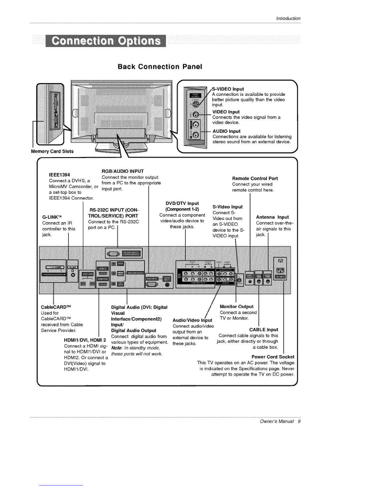
Connection Options ..................... 9
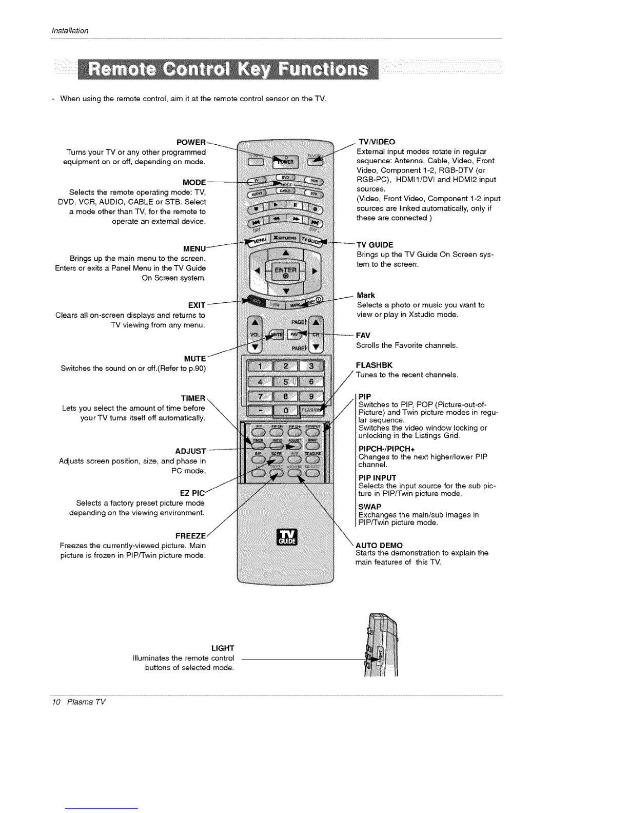
Remote Control Key Functions ......... 10_11
Installation
Accesso ries ............................ 12
Inst_tation Instructions .................. 12~13
Joining tt-_ _ assembly to _ wall to pro_ect tt'_ set tum-
bling .................................. 12
Sv_vel function ......................... 13
Extemat Equipment Connections .......... 14~19
Antenna or Cable Connection ......... 14~15
VCR Setup .......................... 15
External A!V Source Setup ................ 16
DVD Setup ............................ 16
CableCAR D r,_Setup ................ 17
HDSTB Setup .......................... 17
PC Setup ............................. 18
Monitor Out Setup ...................... 19
Digita_ Audio Output ...................... 19
HDMI ............................ 20-22
TV Guide On Screen Setup .............. 23~32
IEEE 1394 ................................ 33-40
TV Guide On Screen TM System ............. 41 ~59
Operation
Turning the TV On ........................ 60
TV Setup
Omscreen Menus Language Selection ...... 61
Setup Menu Options
EZ Scan (Channel Search} ................ 62
Manual Scan ........................... 62
Channel Ed_ .......................... 63
DTV Signal Strength ....................... 63
Channel La_ Setup .................... 64
Main Picture Source Selection ............ 64
Unput Label ............................ 64
Video Menu Options
EZ Picture ............................. 65
Manual Picture Control (Custom Option} ....... 65
Cotor Temperature Control .................. 65
Video Reset ........................... 65
Audio Menu Options
Audio Language .................. 66
EZ SoundR_e /EZ Sound .................. 66
Manual Sound Controm (Custom Option) ...... 66
Front Surround .......................... 67
TV Speakers On/Off setup ............... 67
BBE .......................... 68
Stereo!SAP Broadc_ts Setup .............. 68
Time Menu Options
Auto Ctock Setup ...................... 69
Manual Clock Setup ...................... 69
On/Off Timer Setup ..................... 69
Sfeep Timer /Auto Off .................... 70
Option Menu Features
Aspect Ratio Control ..................... 71
Cinema 3:2 Mode Setup .................. 71
Caption ............................... 72
Caption /Text ......................... 72
Caption Option ......................... 73
ISM Method ........................... 74
Low Power ............................ 75
Auto Demo .......................... 75
Lock Menu Options
Lock Menu Options ..................... 76
Parental Lock Setup ..................... 77
CableCARD _' Function
Cable menu options ..................... 78
ScramMed channel ...................... 78
Cable Channe_ List ...................... 79
Emergency A_ert Message ................. 79
_DIO .......................... 80-85
Remote Control
PIP (Pistureoin-Pi_ure)iPOPfTwin Picture ....... 86
Watching PIP/POP/Twin Picture ............. 86
_ecting an Inp_ S_na_ Source for PIP,Twin Picture, ,86
Swapping PIPfTwin Picture ................ 86
77/Program Select:ion for PIP .............. 86
Moving the PiP sub picture ................. 87
Adjusting Main and Sub Picture Sizes for Twin Picture, ,87
POP(Picture-out-of-Picture: Channel Scan) ..... 87
APM(Adaptive Picture Mode) ................ 88
Brief _nfo ................................. 89
EZ Mute ............................. 90
Freeze & Magnify ....................... 90
Screen Setup for PC mode .................. 91
External Control Device Setup ................ 92~97
IR C_es ................................ 98_99
Programming the Remote ..................... t00
Programming Codes ..................... 101~102
Troubleshooting Checklist ..................... 103
Maintenance , ............................... t04
Product Specifications ........................ 105
After reading this manual, keep it handy for future reference,
6 Plasma TV

Introduction
U
What is a Plasma Display Panel (PDP)?
Aplasma display panel is the lates_display technology and the best way to achieve fiat panel displays with excellent image quality
and large screen sizes that are easily viewab[e_ _e PDP can be thought ofas a descendant of the neon lamp and itcan be atso
be viewed as a series of fluorescent lamps
How does it work?
PDP is an array of cells, known _ pixe_s,which are comprised of 3 sub pixe[s, corresponding to the colors red, green, and blue.
Gas in a plasma state isused to react withphosphors in each subopixel to produce coJored Jight(red, green, or blue). These phos-
phors are the same types used in Cathode Ray Tu_ (CRT) devices such as televisions and com_n computer monitors.
You get the rich, dynamic colors that you expect. Each sub=pixe[ is individually controlled by advanced electronics to produce over
16 mimiion different colors. All of these mean that you get perfect images that are easily viewable in a display that is less than 5
inches thick.
160 ° - Wide angle range of vision
Your ft_ pane[ p_asma screen offers an exception_[y broad viewing angle --over 160 degrees. This means that the dispmay is
dear _d visible to viewers anywhere in the room who can see the screen,
Wide Screen
The screen of the Plasma Disptay is so wide that your viewing experience is as if you are in a theater,
Multimedia
Connect your p[asma display to a PC and you can use it for conferencing games, and _nternet browsing The Picture-in-Picture
feature a_[ows you to view your PC and video images simultaneously
Versatile
The light weight and thin size makes it easy to in_aJl your plasma display in a variety of locations where conventional TVs will not
fit.
The PDP Manufacturing Process: a few minute colored dots may _ present on the PDP _reen
The PDP (Plasma Display Pane_), which is the disptay device of this preduct:_ is composed of 0,9 to 2,2 miltion cell& A few sell
defects will norrr_ify occur in the PDP manufacturing prece_ Several tiny_ minute colored dots visible on the screen should be
acceptabie, This a_so occurs in other PDP manufacturers' products, The tiny dots ap_aring does not mean that this PDP is defec-
tive Thus a few celt defects are not sufficient cause for the PDP to be exchanged or returned. Our production technology mini _
mizes these ceil defects during the manufa_ure and operation of this product
Owner's Manual 7

Introduction
This is a simplified representation of afront panel
- Here shown may be somewhat d_erent from your TV,
Front Panel Controls
iNDEX
Switches
LED
Display on
oroff
Remote Control
Sensor
J | i i
_IHAN_NEL (T, &) Buttons
VOLUME (<U_) Buttons
MENU Button
TViV|DEO Button
TV GU|DE Button
Power Standby Indicator
Hluminates orange in
standby mode,
When the TV is turned on,
the indicator will Mink
green for 3°4 seconds
before the picture is seen,
POWER Button
8 Plas,"na TV

Introduction
Back Connection Panel
pu_
A connection is available to provide
better picture quality than the video
the video signal from a
Memory Card Slots
r'
RGB/AUDIO INPUT
IEEEi394 Connect the monitor output
Connect a DVH S, a from a PC to the appropriate
MicroMV Camcorder, or input port.
a set4op box to
IEEE1394 Connector.
G-LINK TM
Connect an IR
controller to this
jack.
RS-232C INPUT (CON-
TROL!SERVICE) PORT
Connect to the RS,232C
port on a PC
DV D/DTV Input
(Component 1-2)
Connect a component
video/audio device to
these jacks,
Remote Control Port
Connect your wired
remote control here.
_Video Input
Conn_ S-
Video out from
an S=VIDEO
device to the S-
VIDEC) input,
Antenna Input
Connect over4he_
air signals to this
Cab_ARD TM
Used for
CabieCARD TM
received from Cable
Service Provider_
HDMI1/DVI, HDMI 2
Connect a HDMI sig-
nal to HDMI1iDVl or
HDMI2. Or connect a
DVl(Video) signal to
HDMtl/DVl
Digital Audio (DVI: Digital
Visual np/u
int ertace/Oomponent2) AudioP¢ideo I t
Input/ Oonnect audio/video
Digital Audio Output output from an
Connect digital audio from external device to
various types of equipment these jacks
Note:/n standby mode,
these ports will not work
Monitor Output
Conn_ a second
"Pv' or Monitor,
CABLE Input
Connect cable signals to this
iack, either directly or through
a c_bie _x
Power Cord Socket
This TV operates on an AC power, The voltage
is indicated on the Specifications page, Never
attempt to operate the TV on DC power.
Owner's Manual 9

Ins_llation
When using the remote centre{, aim it at the remote contro_ sensor on the TV.
Turns your "CV or any other programmed
equipment on or off, depending on _de.
Selects the remote operating mode: _V,
DVD_ VCR, AUDIO, CABLE or STB. Se[e_
a mode other than TV, for the remote to
o_rate an externa_ device
Brings up the main menu to the screen,
Enters or exffs a PaneJ Menu in the TV Gui_
On Screen system_
Clears aJIon-screen displays and returns to
TV viewing from any menu.
Switches the sound on or off,(Refer to p,90)
TIMER:\
Lets you _etect the amount of time before "\\
your TV turns itseff off autom_atica_y. "_\
ADJUST
Adjusts screen pesffion, size, and phase in
PC mo_
EZ
Selects a factory preset picture mode
depending on the viewing environment.
FRE
Freezes the currentJy-viewed picture. Main
picture is frozen in PIP/Twin picture mo_.
TViV_DEO
Externa_ input modes rotate in regular
sequence: Antenna, Cable, Video, Front
Video, Component 1-2, RGB-DTV (or
RGB-PC)_ HDMII/DW and HDMI2 input
sources_
(Video, Front Video, Component 1-2 input
sources are linked a_om_icalty, oniy if
these are connected )
Bdngs up the TV Guide On Screen sys-
tem to the screen.
Mark
Selects a photo or music you want to
view or play in Xstudio mode.
Scrolls the Favonte channels.
FLASHBK
PIP
Switches to PIP, POP (Picture-ou_-of o
Pi_ure) and Twin pic_re modes in regu-
lar s_uence.
Switches the video win_w locking or
unlocking in the Listings Grid,
PIR;H-/PIPCH+
Changes to the next higher_ower PIP
channel.
PIP INPUT
Selects the input source for the sub pic-
ture in PIP/Twin picture mode.
SWAP
Exchanges the main/sub images in
PIP/Twin picture mode.
Starts the demonstration to explain the
main features of this TV.
LIGHT
IBuminates the remote control
buttons of _]ected mode.
tO Plasma TV

Installation
TV
- Rotates the input mode between Antenna
and Cable,
*Video, Front Video, Component 1-2,
RGB°DTV (or RGS-PC), HDMI1/DVL
HDMJ2
_d IEEE1394 input: sources, screen
returns to the last T\J.
8tings up the menu to select the Photo or
Music mode of Xstudio for memory cards.
THUMBST|CK (Up/Down/LePJRightf F3_%ER)
Allows you to navigate the on-screen menus
and adjust the system settings to your pref-
erence.
1394 (Refer to
VOLUME UP!DOWN
Increases/decreases the sound level
NUMBER
SAP._
Selects MTS sound: Mono, Stereo, and _--_..._
SAP in Analog mo_. Change the audio ]_-
guage in D3V mode,
_lect a dosed caption:
Off, CC1-4, Text1 ~4.
MlC
Remove the Memory
Card.
XsT_la/VCR/DVD control bu_ons
Use for Photo _de or Music mo_
of _J,, _(Refer to p,83, 85)
•Controls the DVHS or Camcorder in
IEEE 1394 mo_.
• Controls some video cassette
recorders or DVD players when you
have already selected DVD or VCR
mode button.
DAY+/DAY-
Moves the Listings Grid forward or back °
ward in 24 hour increments.
Channel information is displayed on top of
the screen, But not available in
Component 1o2, RGB, HDMtl/DW and
HDM_2 mode.(Refer to p.89)
Selects available channels found d_ring
Mat_ua_ s_n.
PAGE UP!PAGE DOWN
Moves from one fult set of screen infor-
mation to the next one.
Changes the aspect ratio.
Selects the sound appropriate for the
program's character.
APM (Adaptive Picture Mode)
Concurrently, compare with the
Dayffght, Normal Night _me and
Castom on _e screen. (Refer to p_88)
Installing Batteries
* Open the battery compartment cover on the back side and instalt the batteries
matching correct polarity:/(+ with +, with -).
* Ins_[[ two 15V AA batteries. Don't mix old or used batteries with new ones.
Replace cover.
Owner's Manual 11

Ins_llation
In !ion
Ensure th_ the following accessories are included with your plasma display. If an accessory is missing, please contact the de_er
where you purchased the product
Owner's Manual Batteries Power Cord Remote Control 75_ Round Cable
2-Wall brackets 2-eye-bolts G-LINK Cable D-sub 15 pin Cable
Secure the TV assembly by joining it to a wall by using the TV,a#Val{ brackets.
Here shown may be somewhat different from your TV,
,,.......
, If the set will be mounted on a desk top, in_
the 2 eye-_ffs and tighten them securely in the upper
holes as shown.
_ns_lI the wall brackets on the wall with 2 boJts*, (not
supplied with the pr_uct), as shown.
Match the height of the eye-boits and the wall brack_
ets
Check to be sure the eye-bo_ts and the brackets are
tighten_ securely.
, _cure the TV as_mbly to the wall with strong strings
or wire cables, (not supplied with the product) as
shown.
12 Plasma TV

Installation
GROUNDING
Ensure that you connect the ea_ ground wire to prevent possible
electric shock_ ff grounding methods are not pessible_ have a qualified
electrician install a separate circuit breaker, Do not try to ground the
unit by connecting it to telephone wires, _ightening rods, or gas pipes
•The TV can be installed in various ways such as on a wail, or on a desktop etc,
• The TV is designed to be mounted horizentaliy,
-Here shown may be somewhat diffe_nt from your TV.
-This manual exprains the features available on the 50PX4D series TVs.
POWer
Supply
Short[.circui!
B_aker
For proper ventilation, a_low a clearance of 4' on each
side and the top, 236 '_on the bottom, and 2" from the
walt Detailed instal}atJon instructions are inctuded in
the optional Desktop Stand Installation
• After installing the TV, you can adjust the the TV set manuatiy to the teft or dght direction by 20 degrees to suit your viewing
posi_on,
Note,; Before adjusting the angle, you must reopen (to the left,) the shaft bolt on the middle of stand's back:
And when stand be level with _you must close (to the right) the shaft bolt to set the hole,
Owner's Manual 13

Ins_llation
1_Analog and Digital TV signals provided on antenna
-Wall Antenna Socket or Outd_r Antenna without a Cable Box Connection
For optimum picture quatity adjust antenna direction if needed.
Mu{t_-family Dwellings/Apartments
_cket)
Bronze Wire
Turn clockwise to tighten,
Bronze Wire
8e careful not to bend the bronze wire when
connecting the antenna,
J
2, Analog and Digital TV signals provided on cable
f
Turn d_kwise [o t_hten=
CabJe TV Wa_l
Jack RF Coaxiai Wire (75 ohm)
14 Plasma TV

Installation
3, Analog and Digital TV signals provided on cable and antenna
Antenna Bronze Wire
RF Coaxial Wire (75 ohm)
Turn ck'_kwise to tighten,
Cable TV Walt 1
Ja_ RF Co_ial Wire (75 ohm) I
Bronze Wire J
88
* To improve the picture quality in a _or signal area,
please purchase a signal amplifier and install properly,
* ff the antenna needs to be spMitfor two TV's, install a "2-
Way Signal Splitter" in the connections.
* If the antenna is not installed properly, contact your deaf
er for assistance.
-To avoid picture noise (interference), _eave an adequate distance between the VCR and TV.
- Use the ISM Method (on the Option menu) feature to avoid having a fixed image remain on the screen for a long period of time.
if the 4:3 picture format is used', the fixed images on the sides of the screen may remain visible on the screen.
Connection Option 1
set VCR output switch to channel 3 or 4 and
then tune the TV to the same channel number.
Connection Option 2
1. Connect the audio and video cables from the
VCR's output jacks to the TV input jacks, as
shown in the figure.
When connecting the TV to VCR, match the
jack colors (Video =yellow, Audio Left = white,
and Audio Right =red).
tf you connect an S-VIDEO output from VCR to
the S-VIDEO input, the picture quality is
improved; compared to connecting a regumar
VCR to the Vi_o input.
2. Insert a video tape into the VCR and press
PLAY on the VCR. (Refer to the VCR owner's
manual.)
3. _lect the input source with using the
"rviV|DEO button on the remote control Note
that this T',/finds the connected input sources
automatically for Video, Front 'video and
Component 1-2. it is presumed tha_ RGB,
HDMI1iDVI and RDMI2 sources are connected.
Do not connect to both Video and
S-Video at the same time.
VCR Rear
Owner's Manual 15

Ins_ltation
How to connect
Connect the audio and video cables from the externaJ equip=
ment's output jacks to the TV input jacks, as shown in the
figure,
When connecting the TV to external equipment, match the
jack colors (Video = yellow, Audio Left = white, and Audio
Right = red),
How to use
1. Select the input source with using the TM/VIDEO button on
the remote control Note that this TV finds the connected
inpt._ sources automatically for Video, Front Video and
Component 1-2. it is presumed that RGB, HDMH/DVt and
HDMI2 sources are connected.
2. Operate the corresponding extema_ equipment. For connec-
tion instructions to operate the TV Guide On Screen system,
see page 23~24.
Video Game
Device
DVD
or
How to connect
1, Connect the DVD video outputs (Y_P_ PR) to the COMPONENT (Y, Ps, P_) _NPUT jacks on the TV and connect the DVD
audio outputs to the AUDIO iNPUT iacks on the TV, as shown in the figure,
2, If your DVD only has an S-Video output jack, connect this to the S=VlDEO input on the TV and connect the DVD audio outputs
to the AUDIO INPUT jacks on the TV, as shown in the figure,
Note: If your D VD player d_e not provide component video output, use S-Video output
How to tl_
1. Turn on the DVD player and then insert a DVD.
2. Use the TVtMIDEO button on the remote control to select Component 1 or Component 2. (if connected to S-VIDEO, select
the Video or Front Video external input source.)
3. Refer to the DVD player's manu_ for operating instructions.
.Component Input ports
To get better picture quality, connec_ a DVD piayer to the compo-
nent input po_s as shown below,
Component ports
on the TV
Video output ports
on DVD player
Notes:
.DigitalAudio will not work for Component t input source.
•Digi_l Audio operation has priority ff D_gilal Audio and AUDIO L/R
are connected at the same time.
16 Plasma TV

Installation
How to use
hse_ the CabteCARD _'_received from the cable service provider to
the CableCARD _"slot of TV back panel
If the pairing information about this TV and the CabteCARD is auto
maticNty displayed on the screen, contact v,4ththe _bLe service
provider.
Note :
.CableCARD '_ have the types of Motero_, Scientific Atlanta SCM etc..
The_ 3 types of CabfeCARD _ can be used for this PLASMA
Caution; When removing the Cab[eCARD _4, do not
drop it as this may cause damage to the
Cab]eCARD _%
-This TV can receive D[gffal Over-the-airiCab_e signals without an external digita_ set4op _x. However, if you do receive Digital
signals from a digital set-top box or other digital external device, refer to the, figure as shown _ow:
-This TV sup_rf_ HDCP (High-bandwidth Digital Contents Protection) protocol for Digi_ Conten_ (_0p,7_p,1080i).
or
Digital Set-top Box
How to connect
Use the TV's COMPONENT (Y, Pe, PR} [NPU_ RGB, HDMiliDVi or
HDMI2 jack for video connections, depending on your set4op box corn
hector, Then, make the corresponding audio connections.
How to use
1. Turn on the digita_ set-top box. (Refer to the owner's manuaJ for the
digita_ set-top box.)
2. Use TV/V|DEO on the remote control to seiect Component 1,
Component 2, RGB-DTV, or HDMII/DV|, HDMI2 source..
S!_na! Componentl_ RGB-DTV, HDM!I/DV]zHDM_
480i Yes No
48££ Yes Yes
7209 Yes Yes
1080i Yes Yes
Owner's Manual 17

Ins_!lation
This TV provi_s Plug and Play capability, meaning that the PC adjusts automatically to the TV's settings.
- The TV perceives 640x480, 60Hz as DTV 480p bacod on the PC graphic card, change the _reen scanning rate for the graphic
card accordingly.
<When the PC supports DVI>
How to connect
1. Connect the PC to HDMI1/DVl port of this TV with an HDMi-to-DV[ cable(not supplied with this product).
If you do not need to c4_nnect audio, HDM[2 port is _so available for the DVl video connection.
2. If the PC(or the sound card of the PC) has a fiber optic digita_ audio output connector, connect the PC's audio output to DIGI-
TAL AUDIO(OPT_CAL) port for DVl iNPUT.
3. ff the PC(or the sound card of the PC) has an anal_ audio output _nnector, connect the PC's audio output to AUDIO INPUT
port }ocated on the right side of RG£ INPUT port.
How To Use
1. To get the best picture quality, adiust the PC graphics card to 1024x768, 60Hz.
2. Select HDMWDW input source in main input option of SETUP menu.(Refer to R84)
TViVIDEO button is also available for this purpose.
3. Check the image on your TV. There may be noise associated with the resolution, vertica_ pattern, contrast or brightness in PC
mode. If noise is present, change the PC output to another resolution, change the refresh rate to another rate or adiust the
brightness and contrast on the WDEO menu uoti[ the picture is c_ear, if the refresh rate of the PC graphic card can not be
changed, change the PC graphic cerd or consult the manufacturer of the PC graphic card.
<When the PC supports RGB>
How to connect
1. Connect the PC to RGB INPUT port of this TV with a RGB cable(not supplied with this product).
2. If the PC(or the sound card of the PC) has an analog audio output connector, connect the PC's audio output to AUDIO INPUT
port _ecated on the right side of RGB iNPUT port:.
How To U_
1. To get the best picture quality, adiust the PC graphics card to 1024x768, 60 Hz_
2. Select RGB-PC input source in main input option of SETUP menu.(Refer to £_)
On_ you select RGB-PC in main input optJon of SETUP menu, TVP',/IDEO button is a_so available for this purpose.
3. Check the image on your TV. There may be noise associated with the resolution, vertical pattern, contrast or brightness in PC
mode. If noise is present:, change the PC output to another recoUution, change the refresh rate to _other rate or adjust the
brightness and contrast on the VfDEO menu until the picture is clear, if the refresh rate of the PC graphic card _n not be
changed, cha_qge the PC graphic card or consuJt the manufacturer of the PC graphic card.
Monitor Display Specifications (RGB-PC)
Horizontal Vertical
Resolution Frequency(KHz) Frequency(Hz)
31,469 70.08
7_x400 37,927 85,03
31 _469 59,94
37.861 72.80
640x480 37.5_ 75.00
43,269 8500
Resolution
800×600
1024x768
Horizontal
Frequency{KHz)
3&156
37.879
48.077
46.875
53.674
48.363
56.476
60,023
Vertical
Frequency(Hz)
5&25
60.31
72.18
75.00
85.06
60.00
70.06
75,02
18 Plasma TV

Installation
Monitor Display Specifications (HDMI/DVI Mode)
Resol_ton
640x480
800x600
Horizontal
Frequency(KHz)
31,469
37.861
37,500
35,156
37_879
48.077
4&875
Frequency{H_
59,94
72,80
75,00
56,25
60,31
72,18
75.00
Resol_ion
1024x768
48,363
56.476
60._3
Vertical
Frequency(Hz)
60.00
70._
75.02
The TV has a special signaJ output capability which allows you to
hook up the second TV or monitor.
Connect the second TV or monitor to the TV's MONITOR OUTPUT,
See the Operating Manuat of the _cond TV or monitor for further
details regarding the device's input settings
Notes:
,Component 1-2, RGB-PC/RGB-DT_ HDMfliDVLHDMI2, DTV
input sources cannot be u_d for Monitor out.
,When connectir_ with external audio equipments, such as amplif-
ers or speakers, please turn the TV speakers off,(Refer to p.67)
,We recommend to use the video and audio output jacks for VCR
recording,
Send the TV's audio to extemaI audio equipment (stereo system) via
the Digital Audio Output (Optical) port,
How to connect
I Connect one end of an optical cable to the T4 Digital Audio
(Optical) Output port,
2, Connect the other end of the optica4 cable to the dig_l audio (opti-
cal) input on the audio equipment
the external audio equipment instruction manual for operation,
Note: When connecting with external audio equipments, such as
ampfifers or _eaker& please turn the TV speakers off,(Refer to
p_67)
Caution: Do not took into the opticat output _rt
Looking at the _er beam may damage
you r vision,
Owner's Manual 19

Installation
HIGH _iNm;_ MUITIMEOtA iNTERFACE
- HDM] TM, the HDMi logo and High-Definition Multimedia interface is a tra_mark or registered trademark of HDMI Ucensing,
This TV can receive the High-Definition Multimedia _nterface(HDMI) or the Digital Visual Interface(DVt)_
= This TV supports HDCP(High-ban@wi@h Digita_ Contents Protection) Protosol for 720x480p, 1280x720p, and 1920x1080i resolu-
tion
- When you connect this TV w_h a source device(DVD ptayer, Set Top Box or PC) suppo_ng A_o HDMIiDV_ function, the output
resolution of the source device will be automaticaJly set to 1280x720p,
- if the source _vice does not support Auto HDM]/DVI, you need to set the output resolution appropriately,
To get the best picture quality, adjust the DVD Player or Set Topi Box's output resol_ion to 1280x720p, and the PC graphi_ _rd's
output resolution to 1024x768, 60,Hz,
- if the source device has an HDMi outpu% no other audio connection is necessa_ _cause HDMFto-HDM[ connection includes
both vi_o and audio,
ffthe source device has aDVI output and no HDM_ output_ a separated audio connection is necessan/_
<:Whenthe source device(DVD player or _t Top Box) supports HDMI>
How To Connect
1. Connect the source device to HDMI1/DVI or HDM_2 port of this TV with an HDMt cable(not supplied with this product),
2_ No separated audio connection is nece_ary_
How To Use
ff the sou rte device supports Auto HDMI function, the output resolution of the source device will _ autema_JcaHy set to 1280x720p_
-tf the source _vice does not support Auto HDM], you need to set the output resolution appropriately
To get the best picture quality, adjust the output resolution of the source device to 1280x720p.
-Select HDMI1!DVl or HDM]2 input source in main input option on the SETUP menu.(Refer to P.64)
TVN|DEO button is also available fo_ this purpose.
•=When the source device(DVD player or _t Top Box) supports DVI>
How To Connect
1. Connect the source device to HDMil/DV] port of this TV with a HDMFto=DVl cable(not supplied with this product).
Do not use HDMt2 p,ort for DVl connection if you want to connect audio.
2. A separated audio connection is necessary:
3. If the source device has a fiber op_c digital audio output, connect the audio output to DIGITAL AUDIO(OPTICAL) port for DV[
INPUT.
4. Connect the PC's audio output to AUDIO iNPUT port located on the right side of RGB INPUT port.
How To Use
- If the source device supports Auto DV] function, the output resolution of the source device will be automaticaBy set to 1280X720p_
If the source device does not support Auto DVI_ you ne_ to set the output resolution appropriately.
To cj_t the best picture qua_it_y, adjust the output resolution of the source device to 1280×720p,
Select HDMI1/DVl input source in main input option on the SETUP menu,(Refer to R_)
TVNIDEO button is a_so available for this purpose,
20 Plasma TV
Other manuals for 50PX4D
4
This manual suits for next models
3
Other LG Plasma TV manuals