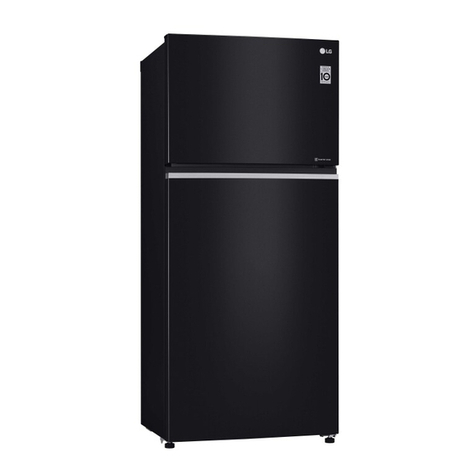
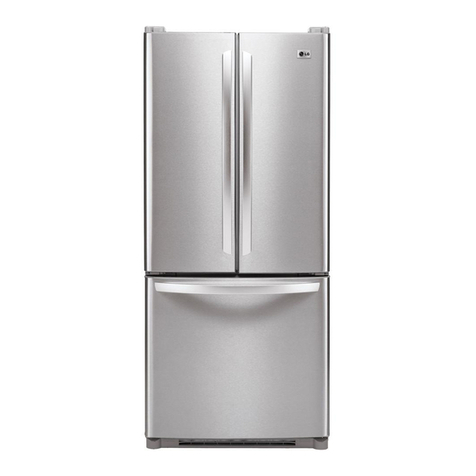
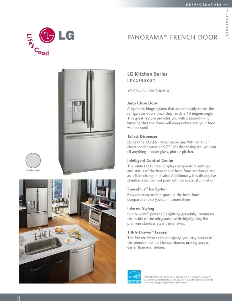
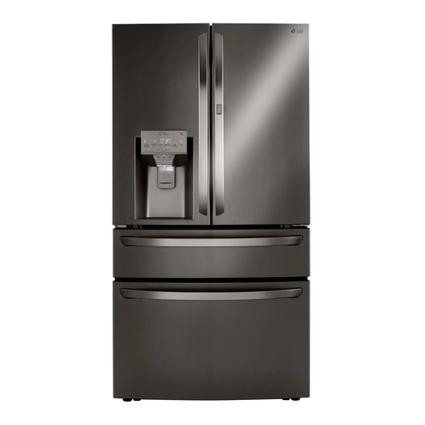
LG GR-J303TS User manual

CAUTION
PLEASE READ CAREFULLY THE SAFETY PRECAUTIONS OF THIS MANUAL
BEFORE CHECKING OR OPERATING THE REFRIGERATOR.
KIMCHI REFRIGERATOR
SERVICE MANUAL
http://biz.lgservice.com
MODEL : GR-J303T*

1. Firstly check that there is electrical leakage in the main body of the product.
2. Perform work always after removing the power plugs in handling with the part where electricity conducts through.
3. Wear a rubber gloves(insulation gloves) for preventing electrical shock accident in case of testing with power on.
4. Always check rated current, voltage and capacity in using the instruments.
5. Exercise care so that water does not enter into electrical parts around the machine room.
6. Take care so that things should not fall down by removing them cleanly on the product when leaning the product forward
or backward. Especially, take care of thin things (glass panels, books).
7. Ensure to consult the repair and maintenance center shop when the cold storage cycle is damaged (to prevent that gas
inside of the cycle gets a room dirty).
SAFETY INSTRUCTIONS
1. Product Specifications ..........................................................................................................................................................3
2. Circuit Diagram ....................................................................................................................................................................5
3. MICOM Function and Explanations of Circuits ....................................................................................................................6
4. Exploded View and Service Parts List ................................................................................................................................34
CONTENTS
- 2 -

1-1. GR-J303T*
1. PRODUCT SPECIFICATIONS
Rating
Defrosting Device
Dimensions (mm)
Net Weight
Motor Power Consumption
Cooling Method
Insulation
Evaporation Dish
Basket
Storage Container
Drawer
Shelf
Flap Door
Low temperature Catalyst
Deodorization
115V/60Hz 115V/60Hz
300 L 300 L
156 L 156 L
144 L144 L
667(W) X 670.4(D) 1775(H)mm 667(W) X 670.4(D) 1775(H)mm
113 Kg 103 Kg
138W 138W
Indirect Cooling System
Force
Automation
Automation
Force
Light Polyurethane Foam
1 EA (Behind)
2 EA
14 EA 8 EA
1 EA 3 EA
3 EA 1 EA
1 EA
2 EA
LC62LBCM
Fin Tube Type
Fin Tube Type
Wire Condenser, Back Plate Condenser
R134a (160 g) R134a (160 g)
α10G 310cc α10G 311cc
Heater, Sheath
Capacity
Defrosting
System
Cooling
Cycle
Net Capacity
Top Compartment
Middle/Bottom
Compartment
Method
Start
End
Evaporation
Compressor
Evaporator of
Top Compartment
Evaporator of
Middle Compartment
Condenser 2 EA
Refirgerant
Refrigerant Oil
ITEMS SPEC SPEC
MODEL GR-J303TG GR-J303TS
- 3 -

- 4 -
P6R8MD P6R8MD
4TM314TFB 4TM314TFB
Ø110 Fan Ø110 Fan
Ø110 Fan Ø110 Fan
Ø110 Fan Ø110 Fan
115 V 140 W 115 V 140 W
115 V 180 W(Half wave 90 W) 115 V 180 W(Half wave 90 W)
120 V(UL) 7 W 120 V(UL) 7 W
Cutted at 70 °C Cutted at 70 °C
250 V 9 A 250 V 9 A
14㎌/ 250Vac 14㎌/ 250Vac
Electrical
System
Rating
Defrosting
Heater
Top
Middle
P.T.C
Overload Protector
Fan Motor(Top)
Fan Motor(Middle)
Condenser
Cooling Fan Motor
Front-C Heater
Fuse-M(Top)
Fuse-M(Middle)
Protection Fuse
Capacitor, R
ITEMS SPEC SPEC

2. CIRCUIT DIAGRAM
- 5 -

3-1. EXPLANATION OF FUNCTION
3-1-1. DISPLAY PART
(1) BEST MODEL(GR-J303TG)
(2) BETTER MODEL(GR-J303TS)
1. MICOM becomes "Lock" status in initial application of power, and the upper room is indicated as "Freezing Food." "Mid",
the middle room as "Cabbage" "Mid", and the lower room as "Cabbage" "Mid".
2. MICOM maintains the previous display status in power failure and re-application of power. But in case of a power-shut or
power reconnection during rhythm fermenting, the temperature returns to "Mid" for the applicable food type.
3. Buzzer sound neither ring ever pressing the button in "Lock" status, nor performs function.
3. MICOM FUNCTION AND EXPLANATIONS OF CIRCUITS
- 6 -
NOTCH
Temperature
setting
Cabbage/Radish/ Mul Kimchi
Vegetble/ Fruit Light Freezing Frozen Food Chilled Food
Min Mid Max Min Mid Max Min Mid Max Min Mid Max Max Min Mid Max
1.0°C -0.5°C -2.0°C 4.5°C 3.5°C 2.5°C -4.0°C -5.0°C -6.0°C -15°C -18°C -21°C -25°C 5.0°C 2.0°C 0.0°C

3-1-2. Food storage/seasoning function
(1) When selecting food type and storage temperature
1. Press the “Lock/Unlock” button for more than 2 seconds to “Unlock” the refrigerator.
2. When you press the “Uppper compartment”, ”Store” button in this condition, the storage temperature level changes from
“Mid” ’ ”Max” ’ ”Min” ’ ”Mid”, and the food type changes as follows when the storage temperature level changes from
“Min” ’ ”Mid”. (“Freeze” ’ ”Refrigerate” ’ ”Kimchi”)
3. When you press the “Middle compartment”, “Storage” button, the storage temperature level changes from “Mid” ’ ”Max”
’ ”Min” ’ ”Mid”, and the food type changes as follows when the storage temperature level changes from “Min” ’ ”Mid”.
(“Cabbage Kimchi” ’ ”Old Kimchi” ’ ”Light freezing” ’ ”Vegetable/fruit”)
4. When you press the “Lower compartment”, “Storage” button, the storage temperature level changes from “Mid” ’ ”Max”
’ ”Min” ’ ”Mid”, and the food type changes as follows when the storage temperature level changes from “Min” ’ ”Mid”.
(“Cabbage Kimchi” ’ ”Old Kimchi” ’ ”Broth Kimchi” ’ ”Vegetable/fruit”)
5. Press the “Lock/Unlock” button to end the food storage and storage temperature selection. At this time, if no button is
selected for 1 minute without the “Lock/Unlock” button pressed, the unit will automatically switch to the Lock condition and
end the selection.
(2) When selecting food type and rhythm fermenting (seasoning)
1. Press the “Lock/Unlock” button for more than 2 seconds to “Unlock” the refrigerator.
2. When you press the “Ferment” button at this condition, the rhythm fermenting (seasoning) changes from “Fermented 1(
)” ’ “Fermented 2 ( )” ’ ”More fermented ( )” ’ ”Underground fermented( )” ’ ”Less fermented 1( )” ’ ”Less
fermented 2( )”, and the food type changes from Middle compartment: “Cabbage Kimchi” ’ ”Old Kimchi” ’ ”Cabbage
Kimchi”, Lower compartment: “Cabbage Kimchi” ’ ”Radish Kimchi” ’ ”Broth Kimchi” ’ ”Cabbage Kimchi” when the
Rhythm Ferment (Seasoning) changes to “Less fermented 2” or “Fermented 1”. (But, the uppper compartment only has
the underground fermenting function.)
3. When you press the Ferment button when the food type is “Vegetable/fruit”, “Light freezing”, it is set to “Cabbage Kimchi
– Fermented 1”.
4. Press the “Lock/Unlock” button to end the food storage and storage temperature selection. At this time, if no button is
selected for 1 minute without the “Lock/Unlock” button pressed, the unit will automatically switch to the Lock condition and
end the selection.
(3) When selecting Flavor Keeping
1. Press the “Lock/Unlock” button for more than 2 seconds to “Unlock” the refrigerator.
2. The Flavor Keeping function can only be selected when the food type of “Cabbage Kimchi”, “Old Kimchi”, “Radish Kimchi”
or “Broth Kimchi” is selected.
3. When you press the “Flavor Keeping” button at this condition, the Flavor Keeping function will toggle between selected
and canceled. (But if both the middle compartment and the lower compartment has food type that can use Flavor
Keeping, operate in the order of Middle compartment Flavor Keeping ON ’ Lower compartment Flavor Keeping ON ’
Middle/Lower compartment Flavor Keeping ON ’ Middle/Lower compartment Flavor Keeping OFF ’ Middle
compartment Flavor Keeping ON.
4. Press the “Lock/Unlock” button to end the Flavor Keeping. At this time, if no button is selected for 1 minute without the
“Lock/Unlock” button pressed, the unit will automatically switch to the Lock condition and end the Flavor Keeping.
5. When you select the Flavor Keeping during the fermenting process, the fermenting will immediately end and the Flavor
Keeping function will start. AT this time, the storage temperature is automatically set to “Mid”.
6. When you select the Flavor Keeping, it controls at lower temperature to keep the current taste of Kimchi longer.
(-1 deg for “Min”, -0.5deg for “Mid” and 0 deg for “Max”.)
7. During the Flavor Keeping operation, the unit runs a cold shock operation every 12 hours.
8. When you select the rhythm fermenting while executing the Flavor Keeping, the Flavor Keeping function will be canceled.
- 7 -
- 8 -
3-1-3. Rhythm fermenting control pattern diagram
1. The fermenting control pattern varies, depending on the temperature of the Kimchi when it is placed into the storage, the
type of Kimchi being made and the degree of the seasoning selected.
2. In the 1st seasoning cycle, if the Kimchi is at room temperature, the cold control operates.
3. During the seasoning cycle, if the Kimchi is cold, the seasoning heater is turned on and if the Kimchi is warm, the
seasoning heater is turned off.
4. If a failure occurs, such as a sensor error during seasoning, the storage will default to Cabbage Kimchi storage status.
5. The 2nd seasoning is not included in the underground fermenting, in the 3rd seasoning, Perform the Low temperature
mature keeping the Temperature is 3 C
Time
Seasoning complete
Kimchi sensor temperature
18 ℃
(Mul Kimchi:
10 ℃)
5 ℃
1.0 ℃
-0.5 ℃
-2.0 ℃
Storage
operation
When the Kimchi placed in
the refrigerator is cool
When the Kimchi
placed in the refrigerator
is at room temperature
1st
seasoning 2nd
seasoning 3rd
seasoning 4th
seasoning 5th
seasoning
Seasoning start
: Seasoning heater
ON/OFF
: Seasoning heater
OFF

- 9 -
3-1-4. TEMPERATURE CONTROL AT UPPER, MIDDLE AND LOWER COMPARTMENT
(1) Temperature control at upper compartment
1. Turn COMP, upper compartment fan motor depending on temperature of the upper compartment sensor and cool them
by opening the 3-way valve to the upper compartment.
2. However, cooling of the upper compartment starts after cooling of the Middle/lower compartment is completed while the
middle/lower compartment is cooling (Max 25 min).
(2) Temperature control at middle/lower compartment
1.Turn COMP, middle compartment fan motor depending on temperature of the middle/lower compartment sensor and cool
them by opening the 3-way valve to the middle/lower compartment ,and opening the middle/lower damper.
2. However, cooling of the middle/lower compartment starts after cooling of the upper compartment is completed while the
upper compartment is cooling (Max 35 min).
(3) Operation conditions of COMP
1. COMP turns on by the upper compartment sensor and lower compartment sensor.
2. COMP turns off by the upper compartment sensor, middle compartment sensor and lower compartment sensor.
(4) Operation conditions of 3-way valve
1. Open the upper, middle and lower compartment valve by the upper, middle or lower compartment sensor .
2. Perform operation for minimum 25 minutes (for 35 minutes at middle, lower compartment) upon request of “open”
(unsatisfactory temperature) at the other side while COMP operates with the valve opened in one side, and then cutoff
the valve to other side. In this case, immediately cutoff the valve if temperature is met even if 25 minutes (35 minutes for
middle, lower compartment) have not passed.
3. In input of initial power, cool from the upper compartment where the upper compartment is Data Frz. (Deep Frz), Frz.
when all upper/middle/lower compartment is not satisfactory, and firstly cool from the middle, lower compartment for the
other case.
3-1-5. LCD BACK LIGHT CONTROL (LIMITED TO LCD MODEL)
1. To make the LCD display easy to see, the LCD back light is turned on for 1 minute for the initial power connection or for
20 seconds for the final button operation.
2. When you press any display button when the back light is turned off, the button command will not be executed nor the
buzzer sound generated. Only the back light will be turned on. But only the “Lock/Unlock”button will operate normally.
(When you press the button when the LCD back light is turned off, only the command to turn on the back light will be
executed.)
3. When you press the “Storage”button of the uppper compartment and the “Storage”button of the lower compartment
simultaneously for more than 1 second, the back light will be turned on and all the graphics on the LCD will be turned on.
When you release the buttons, the LCD graphics will return to the prior condition and the back light turned off.
(LCD graphic and back light ON/OFF check)
3-1-6. LOCK FUNCTION (DISPLAY BUTTON LOCK/UNLOCK)
1. The “Lock”LED is turned on in the Lock status in application of refrigerator power.
2. Turn the “Unlock”LED by pressing the Lock/Unlock button for 2 seconds or more to allow operation of the display button.
3. Buzzer sound neither rings ever by pressing any button other than the Lock/Unlock button, nor performs function with the
“Lock”LED turned on.
4. The “Lock”LED automatically turns on and becomes lock status unless operating the display button for more than a
minute with the “Unlock”LED turned on.

- 10 -
3-1-7. FRONT-C HEATER CONTROL
1. A heater for prevention of dewing is installed on the FRONT-C part between the middle compartment and the lower
compartment, and turns on at the time of COMP ON and for 20 minutes after COMP OFF.
2. It turns off in the test mode (turn on after power off for normal operation).
3-1-8. BUZZER RINGING
1. “Ding~Dong~”sound rings when pressing the front display button.
2. No buzzer rings if pressing the button not according to the operation order.
3-1-9. POWER FAILURE COMPENSATION FUNCTION
1. Previous operation is performs even applying power again after power failure. However, error status or test mode status
is excluded.
3-1-10. OPERATION RESPOND TO AMBIENT TEMPERATURE
1. This is function of maintaining keeping temperature constantly irrespective of season by compensating for the in-
refrigerator temperature through ambient temperature of the refrigerator to prevent that the in-refrigerator temperature
changes according to ambient temperature (weak cold in winter, excess cold in summer).
3-1-11. DEFROSTING (REMOVAL OF FROST)
1. Defrosting is simultaneously performed by using the defrosting heater at the upper compartment and the middle
compartment whenever sum of compressor operation time reaches to 6 hours.
2. Defrosting is started if sum of compressor operation time reaches to 4 hours in input of initial power (or in returning from
power failure).
3. Complete defrosting function where defrosting sensor temperature of each room reaches to 7°C (16°C for GR-J213) for
the upper compartment, 16°C for the middle compartment respectively, after starting defrost work.
However, poor defrost is indicated if not reaching to 7°C (16°C for GR-J213) for the upper compartment, 16°C for the
middle compartment respectively 2 hours after starting defrost (See 3-1-11 Failure Diagnosis Function).
4. Poor defrost is indicated if the defrosting sensor is poor, and defrosting of the relevant room is not done.
-1.5 °C
-0.5 °C
4.0 °C
Keeping Temperature
(based on “Mid”)
Season Spring Summer Fall Winter
Operation Respond to Ambient Temperature
In General Operation

3-1-12. SEQUENTIAL OPERATION OF ELECTRICAL PARTS
Electrical parts such as COMP, defrosting heater at the upper & middle compartment, fan motor at the upper & middle
compartment, single motor damper and FRONT-C heater sequentially operate as followers for preventing noise and
damage of parts occurred by that various parts operate at the same time in input of initial power on and after test closing
(including temporary power failure, either):
- 11 -
Function Operation Sequence Remarks
In initial power on
When
defrosting
sensor
temperature at
the upper
compartment is
more than 45°C
(In purchasing,
movement)
When
defrosting
sensor
temperature at
the upper
compartment is
less than 45°C
(In power
failure, service)
No initial
operation is
done if error
occurs
during
operation.
POWER
ON
SINGLE
MOTOR
DAMPER
ON
COMP
ON F-FAN
ON
SINGLE
MOTOR
DAMPER
OFF
5~6
sec
0.5
sec 3-WAY
VALVE
ON
3-WAY
VALVE
OFF
3~6
sec
0.5
sec
FRONT
-C
HEATER
ON
0.5
sec 0.3
sec 10
sec
0.3
sec 4~5
sec
STEPPING
MOTOR
DAMPER
ON
STEPPING
MOTOR
DAMPER
OFF
POWER
ON
DEFROSTING
HEATER
AT UPPER
COMPARTMENT
ON
DEFROSTING
HEATER
AT MIDDLE
COMPARTMENT
ON
DEFROSTING
HEATER
AT UPPER
COMPARTMENT
OFF
DEFROSTING
HEATER
AT MIDDLE
COMPARTMENT
OFF
FRONT
-C
HEATER
ON
FRONT
-C
HEATER
OFF
SINGLE
MOTOR
DAMPER
ON
COMP
ON
FRONT
-C
HEATER
ON
0.5
sec 0.3
sec 4
sec 0.3
sec 0.3
sec
4
sec
4
sec 0.3
sec 0.3
sec
10
sec 10~30
sec
UPPER
COMPARTMENT
FAN
ON
SINGLE
MOTOR
DAMPER
OFF
0.5
sec 5~6
sec
3-WAY
VALVE
ON
3-WAY
VALVE
OFF
0.5
sec 3~6
sec
STEPPING
MOTOR
DAMPER
ON
STEPPING
MOTOR
DAMPER
OFF

3-1-13. FAILURE DIAGNOSIS FUNCTION
(1) Failure Mode
1. Failure diagnosis function is intended in order that service is easily done when failure to affect performance of the product
during use occurs.
2. Function is neither done, nor buzzer sound rings even when pressing the button in occurrence of failure.
3. The product returns to normal operation if failure is released during display of failure code in occurrence of failure
(RESET).
4. LEDs other than failure code turn off in occurrence of failure.
Note 1) All LEDs except for failure display LED (F1, F2, F3, F4, F5) turn on if simultaneously pressing both upper “Store”
button and middle “Store”button for a second where poor ambient temperature sensor exists.
- 12 -
1
2
3
4
5
6
7
8
9
10
Failure Display
(Food LED)
F1 F2 F3 F4 F5
NO Item Failures Remarks
Failure of upper
compartment (K1)
sensor
Failure of middle
compartment (K2)
sensor
Failure of lower
compartment (K3)
sensor
Failure of upper
compartment
defrosting sensor
Failure of middle
compartment
defrosting sensor
sensor Failure of
ambient
temperature sensor
Failure of single
motor damper
Poor defrosting at
upper compartment
Poor defrosting at
middle compartment
Poor
communication
Upper compartment sensor is disconnected
or shorted
Middle compartment sensor is
disconnected or shorted
Lower compartment sensor is disconnected
or shorted
Upper compartment defrosting sensor is
disconnected or shorted
Middle compartment defrosting sensor is
disconnected or shorted
Ambient temperature sensor is
disconnected or shorted
When ON/OFF of the reed-S/W is not
dectected even when driving the single
motor damper for 2 minutes
When defrosting sensor at the upper compartment
does not reach to more than 7°C even when two
hours have passed after starting defrost
When defrost sensor at the middle compartment
does not reach to more than 16°C even when
two hours have passed after starting defrost
When no communication is consecutively
done for 30 seconds
* Check wiring of respective
relevant sensor.
Damper motor damaged,
frozen, coil damaged, driving
IC(photo coupler) failure
Short of temperature fuse,
short of heater, clogging of
drain, poor heater driving relay
Short of temperature fuse,
short of heater, clogging of
drain, poor heater driving relay
Taking out of connector, Poor
TR on communication part
FS
US
LS
d1
d2
Note 1)
dP
H1
H2
CO
BEST MODEL
(GR-J303TG)
BETTER MODEL
(GR-J303TS)

(2) Load Operation in Failure
- 13 -
Classification
ITEM
NO
UPPER
COMPARTMENT
FAN
COMP
DEFROSTING
HEATER OF
UPPER
COMPARTMENT
DEFROSTING
HEATER OF
MIDDLE
COMPARTMENT
STEPPING
MOTOR
DAMPER
SINGLE
MOTOR
DAMPER
3-WAY
VALVE FRONT-C
HEATER
MIDDLE
COMPARTMENT
FAN
Normal
Failure of
Upper
compartment
(K1) sensor
Failure of
Middle
compartment
(K1) sensor
Failure of
Upper
compartment
(K1) sensor
Failure of
Upper
compartment
defrosting
sensor
Failure of
Middle
compartment
defrosting
sensor
Failure of
ambient
Temperature
sensor
Poor
defrosting
at upper
compartment
Poor
defrosting
at middle
compartment
Failure of
single
motor
damper
Poor
communication
1
2
3
4
5
6
7
8
9
10
11
O
15 min
ON/
15 min
OFF
O
O
O
O
O
O
O
O
O
O
O
O
O
O
O
O
O
O
O
O
O
O
O
O
O
O
O
O
O
O
O
O
O
O
O
Don’t
defrost
(immediat
ely return)
O
O
O
O
O
O
O
O
O
O
O
Don’t
defrost
(immediat
ely return)
O
O
O
O
O
O
O
15 min
OPEN/
15 min
CLOSE
O
O
O
(No
compensation
of ambient
temperature
)
O
O
O
O
O
O
O
10 min
OPEN/
15 min
CLOSE
O
O
(No
compensation
of ambient
temperature
)
O
O
Perform
normal
initialization
by checking
operation
in the cycle
of 1 hour
O
O
O
(Linked
with
COMP.
However,
FRONT-C
heater
turns off
for 15
minutes
and turn
on again if
the heater
turn on
time
continues
for more
than 40
minutes)

3-1-14. TEST FUNCTION
1. Test function is intended to check function of PCB and the product and find a failure part with failure status.
2. The test S/W exists on the main PCB, and ends the test mode after 2 hours irrespective of the test mode, and then
returns to normal status.
3. Function button is neither detected, nor button recognition sound comes out during the test mode.
4. Ensure to take the power cords out in completion of the test mode so that normal status will be arrived.
5. Release the test mode and display the failure mode if failure such as sensor failure during the test mode.
6. No test mode is performed even when pressing the test button during display of failure code.
•LED check function
All LEDs turn on if pressing both upper “Store”button and middle “Store”button at the same time for 1 second or more,
and display the previous status if releasing the button.
•FRONT-C Heater touching inspection mode
The FRONT-C heater consecutively turns on for 5 minutes and is then released if pressing both upper “Store”button and
lower “Ferment”button for 5 seconds or more. It is released if pressing them again for 5 senconds or more.
- Release check: LED on the remainder time display part of the lower compartment turns on with pressing for 5 seconds or
more.
- Input check: LED on the flavor keeping part turns on with pressing for 5 seconds or more.
- 14 -
MODE OPERATION DETAILS REMARKS
TEST1
TEST2
Normal
status
Press the test S/W
once
Press the test S/W
once in the test mode 1
Press the test S/W 3
times in the test mode 2
1. COMP (* Fan motor at machine room) ON
2. Defrost heater OFF at upper, middle compartment.
3. FRONT-C heater OFF
4. Fan motor at upper/middle compartment, damper
at middle/lower compartment and 3-way valve
operates to cool the upper/middle&lower
compartment in interval of 16/24 minute.
5. For display, the only “Min”LED of the upper room
turns on.
1. COMP (* Fan motor at machine room) OFF
2. Fan motor OFF at upper, middle compartment
3. Defrost heater ON at upper, middle compartment
4. FRONT-C heater ON
5. All dampers at middle, lower compartment are
closed.
6. 3-way valve maintains previous status.
7. For display, the only “MIN”LED of the upper room
turns on.
Returns to initial status
Returns to normal status
when maximum 2 hours
have passed.
Defrost sensor at the
upper compartment
performs initialization at
more than 7 °C, and
middle defrost sensor at
more than 16 °C (COMP
delay for 7 minutes)
COMP operates after
delay for 7 minutes

3-2. EXPLANATION OF CIRCUITS
3-2-1. POWER CIRCUIT
Power circuits consist of SMPS (Switching Mode Power Supply) power, and the SMPS consists of the rectification part
(BD1, CE1) to convert AC voltage to DC voltage, the switching part (IC3) to switch the converted DC voltage, a transformer
to transfer energy of the primary side on the switching terminal, secondary side power to supply power to the MICOM and
IC and the feed back part (IC4, IC5) to feedback the secondary side voltage to the primary side of transformer in order to
maintain it uniformly.
Caution.: Take a measure after more than 3 minutes have passed after removing the power cords in abnormal operation of
circuits since high voltage (DC310V) is maintained at the power terminal. Otherwise, it may cause electric shock.
Voltage of each part is as follows:
3-2-2. OSCILLATION CIRCUIT
Oscillation circuits are intended to generate clock for
synchronization for information transmission/receipt of logic
elements inside of the IC1 (MICOM) and generate basic time for
time calculation. Rated parts must be used since the OSC1 does
not operate or time calculated at the IC1 changes where SPEC
changes.
3-2-3. RESET CIRCUIT
The reset circuits are intended so that the whole of function is
started at the initial status by initializing various parts such as ram
inside of the MICOM (IC1) when power is applied to MICOM
again in input of initial power or by temporary power failure.
“LOW”voltage is applied to the reset terminal of MICOM for the
fixed time (10ms) at the start of power input.
During general operation, the reset terminal is at 5V (No MICOM
operates in case of poor reset IC).
- 15 -
Part Both ends of VA1 Both ends of CE1 Both ends of CE2 Both ends of CE3 Both ends of CE4
Voltage 220 Vac 310 Vdc 16 Vdc 12.5 Vdc 5 Vdc

3-2-4. LOAD/BUZZER DRIVE CRICUIT
(1) Load Drive Circuit
Type of Load
COMP,
Mechanical
Area FAN
UPPER
FAN
MOTOR
UPPER
DEFROST
HEATER
FRONT-C
HEATER
SINGLE
MOTOR
DAMPER
MIDDLE
DEFROST
HEATER
MIDDLE
FERMENT
HEATER
LOWER
FERMENT
HEATER
MIDDLE
FAN
MOTOR
Measuring Point(IC7) No.10 No.16 No.12
Q1 Collector
No.11 No.15 No.13 Q2Colletor No.14
Status ON Within 1V
OFF 11 ~ 13 V
- 16 -

(2) Buzzer driving circuit (located on display PCB)
g Only the buzzer sound for the Lock/Unlock operation is shown in this SVC technical manual.
3-2-5. SWITCH INPUT CIRCUIT
Following circuits are input circuits for detecting signal of the test switch for checking refrigerator or the reed switch of the
single motor damper.
- 17 -
REED Switch
78
79
P35
(INT1)
P36
(PWM3/TC3/PDO3)
LED MODULE TYPE
Ex) Lock: "Ding-D-Dong" sound Ex) Lock: "Ding-D-Dong" sound Off
IC101 (Pin 3/61)
5V
IC101 (Pin 2/62)
0V
Measuring
point
Status
45ms
1046.5Hz 1174.7Hz 1318.5Hz
45ms 45ms 45ms 70ms 750ms
5V
0V
5V
0V
45ms
1568.0Hz 1318.5Hz 1046.5Hz
45ms 45ms 45ms 70ms 750ms
5V
0V
5V
0V

3-2-6. TEMPERATURE SENSING CIRCUIT
Above circuits consist of the upper sensor, middle sensor, lower sensor for adjusting setup temperature at the upper, middle
and lower compartment, the ambient temperature sensor to detect ambient air temperature, the upper defrost sensor and
the middle defrost sensor attached to the evaporator at the upper, middle compartment to detect the defrost return
temperature. Status in short or open are as follows:
- 18 -
(외기 센서)
Ⓐ
Ⓑ
Ⓒ
Ⓓ
Ⓔ
Ⓕ
(LED:6871JB1400, LCD:6871JB1399)
Sensor Check points Normal (-30 °C ~ 50 °C) In Short In Open
Ambient temp. Sensor
Upper Sensor
Middle Sensor
Lower Sensor
Upper Defrost Sensor
Middle Defrost Sensor
0.5V ~ 4.5V 0V 5V
POINT ⒶVoltage
POINT ⒷVoltage
POINT ⒸVoltage
POINT ⒹVoltage
POINT ⒺVoltage
POINT ⒻVoltage

3-2-7. TEMPERATURE SENSING CIRCUIT
1.Temperature adjustment at the lower compartment consists of the circuit part for driving the damper, as electronic single
motor damper, to open or close the baffle and the reed switch part to detect open/close status of the damper.
2. Drives the motor, and if there is no status change of the reed switch within 2 minutes, determines it as failure and displays
as failure (See 3-1-11. Failure Diagnosis Function).
3. Rotates once for 15 seconds irrespective of temperature to detect damper status in input of initial power (initial drive
inspection).
4. Open/Close of the damper, status of the reed switch and No.1 pin input of the IC1 (MICOM) are as follows:
<SINGLE MOTOR DAMPER>
uThe above time is time until the single motor stops after status change of the reed switch.
- 19 -
Single Motor Damper 100V~127V
deleted
Open/Close status
of lower damper
Single Damper
Reed Switch
IC1 (MICOM) “H”: 5V
No.1 pin input “L”: 0V
2sec
Operation Stop
Operation Stop
OPEN
CLOSE
ON
OFF
Position
Lower Damper status
Open
Close

3-2-8. STEPPING MOTOR DAMPER DRIVE CIRCUIT (FOR TEMPERATURE CONTROL AT MIDDLE COMPARTMENT)
As for motor drive, the motor rotates since rotation magnetic force is formed at coils wound around each phase of the motor
and the stator if outputting “High”“Low”signal as much as the fixed step numbers through the MICOM pin 51 and pin 52
after applying “High”signal to the IC 12 (TA777AP) from the MICOM pin 53.
Explanation) For driving method of the motor, send signal in the cycle of 3.33ms by using the terminal of the MICOM PIN53,
52 and 51 as shown in waveform of each part below. This signal is output to the output terminal No.10, 11, 14,
15 via the input terminal No.3, 6, 8 of the IC12 (TA7774P) as IC for motor drive. The motor rotates by which
motor coils wound around each phase of the stator forms rotation magnetic field. The stepping motor damper
rotates by which motor coils wound around each phase of the stator forms rotation magnetic field if inputting as
figure to the input part (No.3 INA, No.6 INB) of the IC12 (TA7774P) for motor drive.
- 20 -
하칸 온도 제어용
IC12 No.3 (INA)
IC12 No.6 (INB)
IC12 No.15 (A)
IC12 No.10 (B)
IC12 No.14 (A)
IC12 No.11 (B)
CCW (reverse rotation) CW (positive rotation)
This manual suits for next models
1
Table of contents
Other LG Refrigerator manuals
Popular Refrigerator manuals by other brands

Polar Refrigeration
Polar Refrigeration CE322 instruction manual

Blomberg
Blomberg SSM 1350 user manual

Marvel
Marvel 30ARM-BB-F Installation, operation and maintenance instructions

Fagor
Fagor FA256 Instructions for use

Whirlpool
Whirlpool W8TXEWFYB Energy guide

Frigidaire
Frigidaire Gallery FGHN2844L E Specifications