3. DISASSEMBLY
3-1 REMOVING AND REPLACING REFRIGERATOR
To remove and replace the refrigerator door:
CAUTION: Before you begin, remove food and
bins from the doors.
• Open the door. Remove the top hinge cover screw (1) and
screw (1) and lift up the cover(2).
• Remove the cover.
• Disconnect wire harnesses (3).
• Remove the grounding screw (4).
• Using 10mm or 13/32-inch socket wrench, remove the 3 bolts
and lift off the Top Hinge(5). Set parts aside.
: When removing the bolts, be careful that the
door does not fall forward.
• Lift the door from the middle hinge pin and remove the door.
• Place the door, inside facing up, on a non-scratching surface.
• Replace in the reverse order.
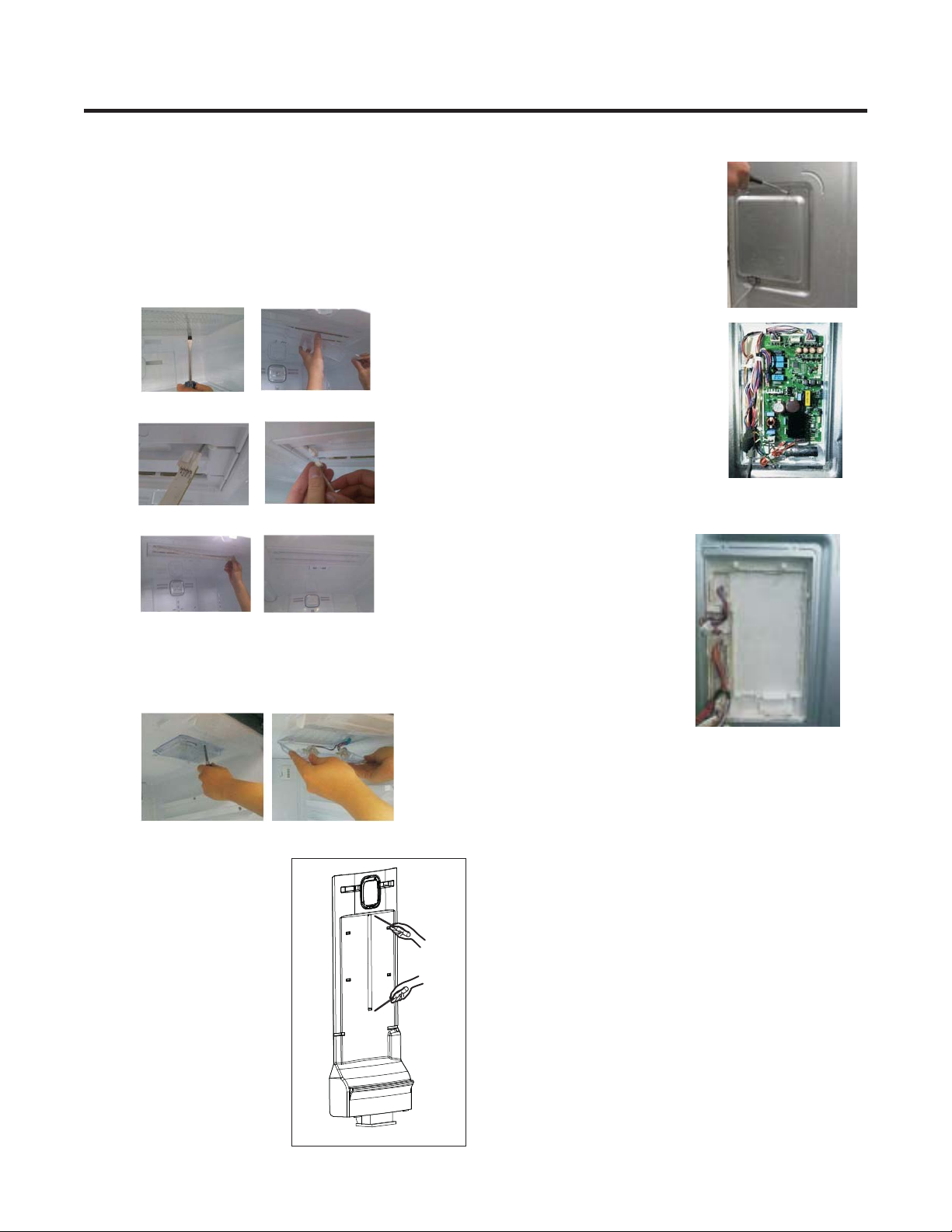
IMPORTANT
• Mullion Removal
1. Remove 2 screws.
2. Lift mullion up carefully.
3. Disconnect wire harness.
• Door Gasket Removal
• Door Gasket Replacement
• Mullion Replacement
1. Remove gasket.
Pull gasket free from gasket channel of the four remaining
sides of door.
1. Insert gasket into channel
Press gasket into channels on the four remaining
sides of door.
1. Connect wire harness.
2. Insert mullion into channel.
Inserting mullion assy’ into bracket, door.
3. Assemble 2 screws.
DOOR
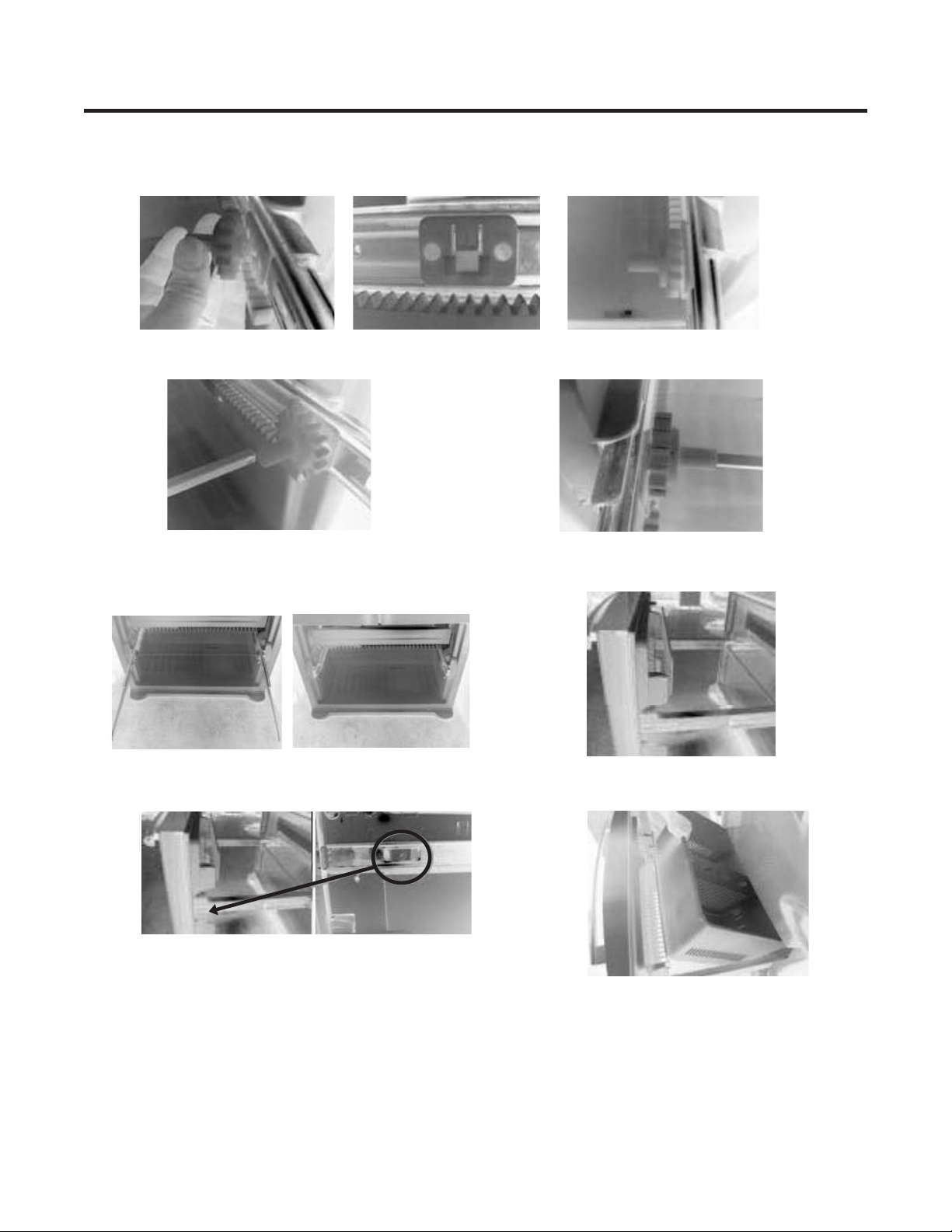
To remove the right refrigerator door:
• Open the door. Remove the top hinge cover screw (1) and
screw (1) and lift up the cover(2).
• Remove the cover.
• Disconnect wire harnesses (3).
• Remove the grounding screw (4).
• Using 10mm or 13/32-inch socket wrench, remove the 3 bolts
and lift off the Top Hinge(5). Set parts aside.
: When removing the bolts, be careful that the
door does not fall forward.
• Lift the door from the middle hinge pin and remove the door.
• Place the door, inside facing up, on a non-scratching surface.
• Replace in the reverse order.
IMPORTANT
3-2 DOOR
6