LG LSSB2791ST User manual

LSSB2791ST
REFRIGERATOR
SERVICE MANUAL

2
Table of Contents
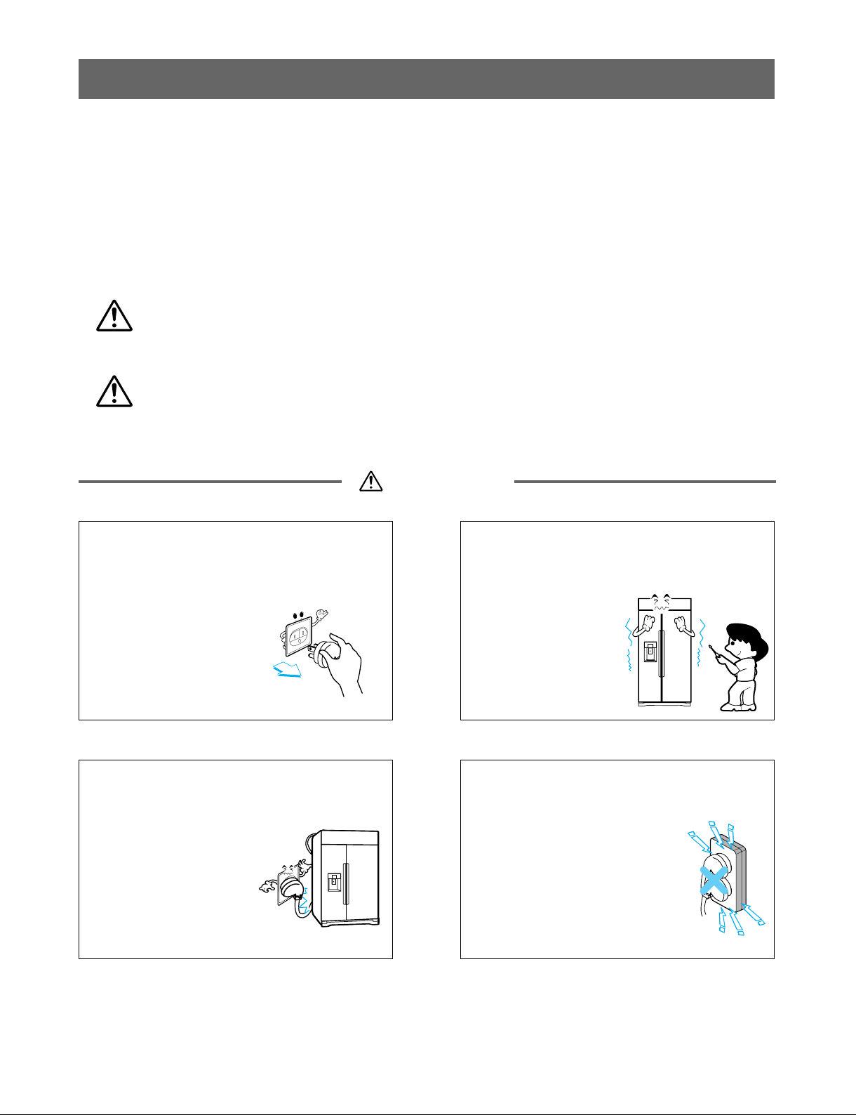
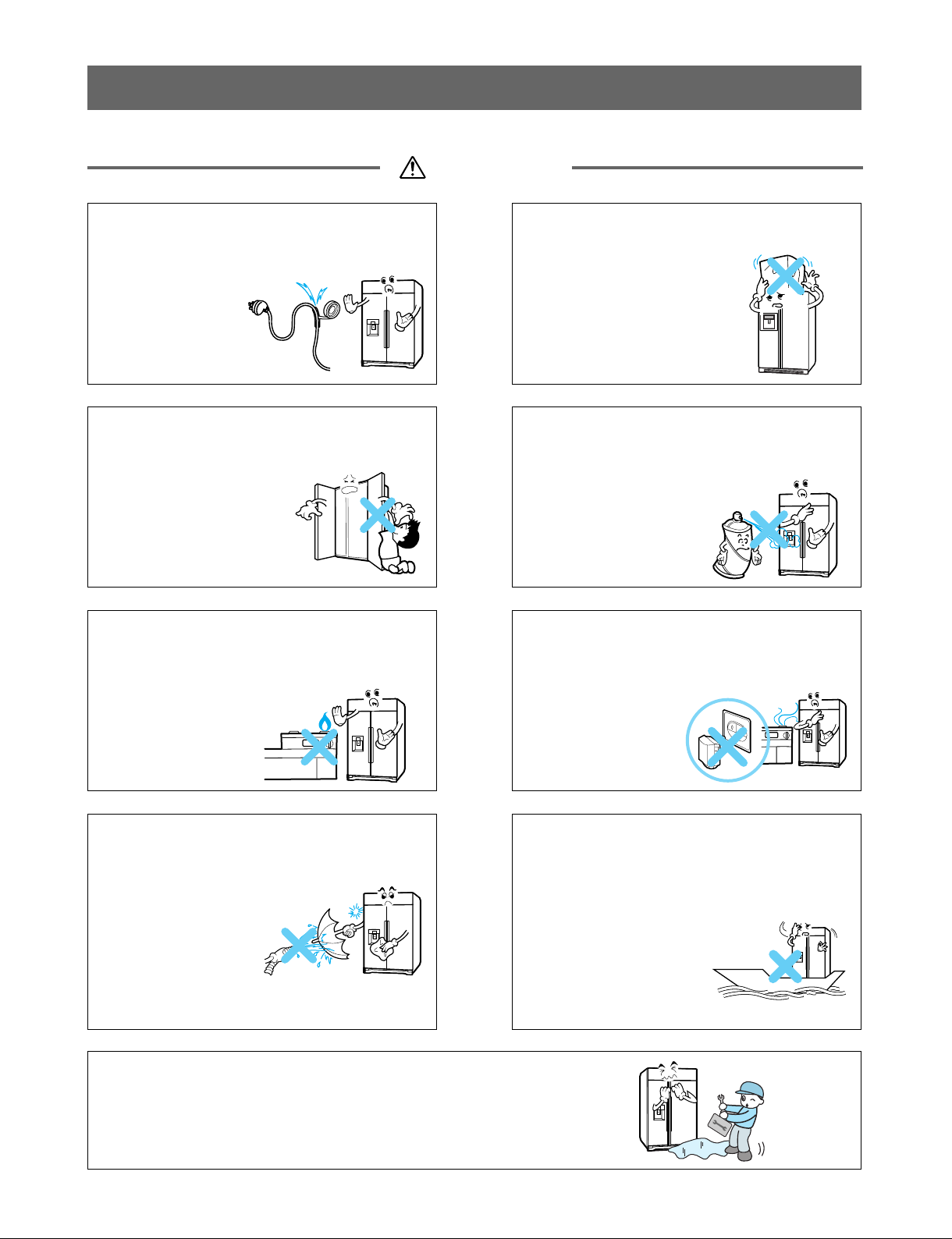
Chapter 1 Safety Warning and Cautions ........................................................................................ 3
Chapter 2 Product Standards ......................................................................................................... 8
Chapter 3 Circuit Diagram ............................................................................................................... 9
Chapter 4 Specifications ............................................................................................................... 10
1. Specifications ............................................................................................................................... 10
2. Parts ............................................................................................................................................. 11
Chapter 5 Micom Function ............................................................................................................ 13
1. Control Panel Figure .................................................................................................................... 13
2. Description of Function ................................................................................................................ 14
Chapter 6 Icemaker and Dispenser Operation and Repair ........................................................ 20
1. Operation ..................................................................................................................................... 20
2. Icemaker Functions ...................................................................................................................... 21
3. Defect Diagnosis Functions ......................................................................................................... 22
Chapter 7 Trouble Diagnosis ........................................................................................................ 23
1. Sealed System Repair ................................................................................................................. 23
Chapter 8 Troubleshooting ........................................................................................................... 30
1. Troubleshooting by Error Codes .................................................................................................. 30
Chapter 9 How to Disassemble and Assemble ............................................................................ 56
1. Door .............................................................................................................................................. 56
2. Handle .......................................................................................................................................... 57
3-1. Dispenser .................................................................................................................................. 57
3-2. Display PCB ............................................................................................................................. 57
3-3. Ice Button .................................................................................................................................. 58
3-4. Water Button ............................................................................................................................. 58
3-5. Duct Door .................................................................................................................................. 58
3-6. Cap Duct Motor ......................................................................................................................... 58
3-7. Funnel ....................................................................................................................................... 58
4. Water Valve Disassembly Method .............................................................................................. 59
5. Fan and Fan Motor Disassembly Method .................................................................................... 59
6-1. Multi Duct Freezer .................................................................................................................... 60
6-2. Grille Fan Freezer...................................................................................................................... 60
6-3. Multi Duct Refrigerator .............................................................................................................. 60
6-4. Grille Fan Refrigerator .............................................................................................................. 60
7-1. Lamp Cover (Back).................................................................................................................... 61
7-2. Lamp Cover (Side)..................................................................................................................... 61
8. Airtight Compartment .................................................................................................................... 62
Exploded View ................................................................................................................................ 63

3
Safety Warning and Cautions
▶Observing cautions for safety can prevent accidents and dangers.
▶Cautions are classified into Warning and Caution and the meanings are as follows
Warning
Warning WARNING indicates the possibility of serious injury or death if the instructions
are not followed.
Caution Caution indicates a hazardous situation with the possibility of product damage
or personal injury if the instructions are not followed.
Be cautious of electric shock.
Control board (PWB Main and Sub)
uses power supply of about 120 VAC.
Be sure the plug and cord are not
pressed by the rear side of the
refrigerator.
Damage to power plugs
could result in fire or
electric shock.
Plug the refrigerator into a
dedicated circuit.
Plugging in too many appliances
can result in fire or problems with
the operation of your refrigerator.
Do not allow consumers to directly
repair, disassemble, or modify the
refrigerator.
Harm, electric shock,
or fire could occur.
Chapter 1 Safety Warning and Cautions

4
Safety warnings and cautions
Warning
Do not store poisonous,
flammable, or explosive chemicals
in the refrigerator.
There is danger of
explosion and fire.
EtherBenzene
Chemical
drugs
LP gas
Do not store medications or
biohazardous products requiring
precise temperature control.
Do not use the refrigerator to store
papers, electronic storage media,
or similar items.
The refrigerator is
for storing food.
This is a consumer
household
appliance and not a
precision device.
If storing or disposing of the
refrigerator, remove the doors
to eliminate the possibility of
children playing in it.
Children may
become entrapped in
the refrigerator.
Unplug the refrigerator for
cleaning or repair. Be sure your
hands are dry when handling the
power cord or plug.
Electric shock or
harm may occur.
Be sure the plug and socket are
clean and the connection is tight.
Dust or incomplete
connection may
result in fire.

5
Safety warnings and cautions
Warning
Do not alter the power cord.
Replace it only with an exact factory
replacement part.
Electric shock or
fire may occur
due to electrical
damage of power
cables.
Do not place heavy objects on the
refrigerator.
Falling objects when
opening or closing doors
may cause injury.
Do not hang or swing from the
refrigerator doors.
Do not allow children to
play with the refrigerator.
The refrigerator may turn
over. Hands and fingers
may be pinched.
Do not use flammables near a
refrigerator.
There is danger of fire.
Do not install the refrigerator next
to a stove or other sources of heat.
There is danger of fire.
When a gas leak occurs, do not
unplug the refrigerator. Open the
doors for ventilation.
There is danger of
burning due to
explosion and
sparking.
Do not clean the refrigerator by
spraying water inside or outside.
It may result in
product damage,
fire, or electric
shock.
This refrigerator is designed for
use as a consumer home
appliance only.
It is not a precision
device for storing
medication or valuables.
Do not install the
refrigerator in a vehicle,
aircraft, maritime vessel,
or other than in a home
environment.
If the refrigerator is submerged or otherwise inundated
with water, have it checked by an authorized servicer.
Electric shock or fire may occur.

6
Safety warnings and cautions
Caution
Do not put glass bottles or other
sealed containers in the freezer.
They may burst, leaving
glass fragments in the food
and possibly causing injury.
Be sure to use rated parts for
replacement of electric parts.
Use factory replacement parts.
Secure the cord behind the
refrigerator.
Do not allow the cord to
hang where it can be
pinched, damaged, or rolled
over by the refrigerator.
Pull the plug out by the plug body;
do not pull the wire to disconnect
the cord.
Damage to power cords
may cause fire or electric
shock.
Keep electrical parts and
connections free from dust and
contamination.
There is danger of fire
from shorting or arcing.
Be sure replacement parts are an
exact fit.
Replacement parts should look
and fit exactly like the original
parts and have the same electric
rating.
Do not let moisture drop onto
electrical parts.
If there is a problem in this area, replace the
parts or tape the wires to prevent
contamination and degradation.
If you unplug the refrigerator or
turn off the power, wait 5 minutes
before plugging it back in
or turning the power on.
Rapid cycling of the compressor
could cause failure.
Do not put your hands, fingers, tools, or other
objects into the icemaker, crusher, or discharge
outlet. Do not check the operation of the ice
dispenser or crusher in this manner.
You may damage your product, fingers, or tools.

7
Safety warnings and cautions
Caution
Unplug the refrigerator if it is
going to be unused for an
extended period.
Remove all food items,
wipe down the inside of
the refrigerator, dry it
thoroughly, and prop the
doors open to allow air
circulation.
Be sure the floor will support the
weight of the refrigerator.
If the refrigerator is not installed
at a firm, level location, the
doors and icemaker may not
operate properly.
Do not install the refrigerator in a
place where it is subject to
splashing and excess moisture.
Deterioration of insulation
may cause electrical
leakage.
Do not touch foods, containers, or
the inside of the freezer
compartment with wet hands.
Your hands may stick
to the cold items. It
could cause frost bite.
Be careful to avoid pinching hands
or feet when opening the doors.
Do not stick your hands or fingers
under the bottom of the
refrigerator.
Watch out for sharp
edges.
Do not put live animals in the
refrigerator.

8
Product Standards
Chapter 2 Product Standards
Effective inner
capacity
Heater
Rated consumption power
Temperature control
Defrost
Freezer
Refrigerator
Freezer
Refrigerator
Freezer
Refrigerator
Method
Start
End
Insulation
Type of heat shield
Shelf
Door Basket
In-door icemaker
drawer
Shelf
Door Basket
Magic room
Drawer
Outer dimension (W x D x H)
Rated voltage and frequency
Product weight (kg)
Rated consumption power of motor
Cooling method
Total inner capacity(L)
F-Room
R-Room
GR-LSSB2791ST
Model Name
Divison
Freezing cycle
Electrical
parts
standard
Ice and water
dispenser
Compressor driving method
Evaporator
Condenser
Compressor Oil
Type of refrigerant
Dryer (Capillary Tube)
Overload protective device
Cold/freezing fan motor
Fan motor for cooling condenser
Inside lamp at Freezer
Inside lamp at Refrigerator
Freezer-Lower lamp switch
Door switch (Freezer and Refrigerator Compartments)
Home bar door switch
Freezer-Lower lamp
Main Fuse
Power cord
Icemaker unit
Ice feeding and crushing motor
(Motor, geared)
Solenoid cube
Duct door motor
Water valve
Pump (option)
Capillary tube
Product
-related parts
Parts consens
ation with
dewing
prevention
For preventing
ice making
For controlling the
temperature in
Magic Room
Freezer
Refrigerator
Initial defrost
Defrost cycle
Rest time
Defrost sensor
Temp. fuse (rated/ operation temperature)
Heater sheath
Dispenser duct door heater
Dispenser heater
Refrigerator home bar heater
Freezer home bar heater
Water supply heater
Drain Heater
Drain Pipe Heater
750 (26.5 cu ft)
289 (10.2 cu ft)
461 (16.3 cu ft)
1067 X 645 X 2114 (42in X 25.4in X 83.2in)
115V / 60Hz
244 (538lb)
90 ±15% [W]
200 ±15% [W]
160 ±15% [W]
Indirect cooling (Freezer/Refrigerator Control)
Micom (Outside)
Micom (Outside)
Forced method
Auto
Auto
Forced method
Cyclo-Pentane
4
2ea
1
3
4
5 (Easy moving 3ea)
-
3
IPM operation
Fin tube type
Forced convection method
FREOL-α10G (180cc)
HFC-134a (170g)
0.75
0.9
MOLECULAR SIEVE XH-9
4~5 hours (vary depending on condition)
9~11 hours (vary depending on condition)
Freezer 5 Minutes / Refrigerator 7 minutes
Freeze -41°F, Refrigerator - Returns to normal operation when it reaches 50°F
115 / 162°F
120 VAC (Freezer 200 W, Refrigerator 150 W)
-
DC 3 W
-
-
DC 0.8 W
DC 12 / 2.6 W
DC 12 V / 1 W
-
13 VDC
14 VDC
12 VDC / 8.7 W
12 VDC / 8.7 W
-
-
-
-
120 VAC / 9 A
120 VAC / 10 A
DC 12VDC
120 VAC / 60 Hz / 16.5 RPM
120 VAC / 60 Hz
DC 12VDC
120 VAC / 60 Hz
-

9
Circuit Diagram
MODEL LSSB2791ST
Chapter 3 Circuit Diagram

10
Specifications
1. Specifications
Chapter 4 Specifications
I
Width
Depth
Height
Minimum air circulation space
Width (A)
Frame to frame(B)
When opening door by 90° (including handle) (C)
Case (including back handle) (D)
After disassembling door (including hinge,L) (E)
Including door (not including handle) (F)
Including handle (G)
When opening door by 90° (H)
At rear (I)
From Floor to Front,Pannel (J)
Top part
Side
Rear part
41 (1041)
42 (1067)
45 (1143)
22 1/2 (572)
25 1/2 (649)
25 3/8 (645)
27 1/2 (698.5)
48 1/3 (1228)
83 1/4 (2114)
82 1/2 (2098)
1/4 (6)
1/4 (6)
1/6 (4)
Unit : inch (mm)
Front View
Top View

11
Specifications
2. Parts
MODEL LSSB2791ST
Automatic
Icemaker
Freezer
Compartment
Refrigerator
Compartment
Door Rack (2)
Drawer (3)
Drawer (3)
Lower Cover
Shelf (8)
Top Cover
LED Function
displayboard
Moving Basket (3)
Dairy Corner
Gallon Basket

①②③④⑤⑥⑦
⑧⑨
⑩⑪
⑫
12
Micom Function
1. Control Panel
Chapter 5 Micom Function
①Power off : Unit Power on/off of refrigerater.
②Quick freezing : When the Quick freezing button is pressed, the display will indicate the selected
function has been activated.
③FRZ TEMP : Indicates the set temperature of the freezer compartment in Celsius or Fahrenheit.
④REF TEMP : Indicates the set temperature of the refrigerator compartment in Celsius or Fahrenheit.
⑤ALARM : This indicator shows that the door-open warning alarm is activated.
⑥Filter reset : This indicator shows the current status for the water filter. See Restting the Filter Indicator
⑦SVC Call : Call SVC center, when SVC call Icon is turned on.
⑧Display of setted temperature of F - room
⑨Display of setted temperature of R - room
⑩Activating Energy saving : Press the ENERGY SAVING button for at least 3 seconds to activate or deactivate the
function. This function is recommended for added energy savings. (Some heaters to reduceexess moisture on the
Refrigerator may be turned off) The Energy saving function is also recommended during long periods of time spent away
from home-like vacation.
⑪Lock State : Indicator shows the current status for the control panel functions is set to LOCK.
⑫Dispenser selection indicator : Shows water, cubed ice or crushed Ice selection that will be dispensed
when the push switch is pressed.
1-2. Display Second Function
1. Alarm mute Mode
When the power of the refrigerator is turned on for the first time, the buzzer icon lights up and when the door is opened for a
long time, the buzzer goes off.
Press the Alarm/Lock key once to activate and again to deactivate the function.
2. Display Power saving Mode
If there is no entry 20~60 seconds after the power of the display is turned on (60 seconds if no button is pressed after the
power is turned on and 20 seconds when a button is pressed), it automatically switches to the power saving mode to display
only the current selection of dispenser and lock status. All icons on the display will be turned on when the door is opened or
the button is pressed.
When you want to cancel the power saving mode, press and hold the Quick Freezing button and Freezer Button
simultaneously for more than 5 seconds, and when the mode is canceled, all segments of the displays shows the current
status.
If you want to use the Power Saving Mode again, press the same buttons in the same method as canceling.

13
Micom Function
2. Function description
2-1. Function of Temperature Selection
Notch
Change of
Indication lamp
Room Temp.
Freezer Control
(88 LED)
Power Initially On
1st press
0°F
0.4°F
0.5°F
-1°F
-1.3°F
-0.4°F
-2°F
-2.2°F
-1.3°F
-3°F
-3.1°F
-2.2°F
-4°F
-4.0°F
-3.1°F
-6°F
-5.8°F
-4.9°F
8°F
8.6°F
10.4°F
6°F
6.8°F
7.7°F
5°F
5.0°F
5.9°F
4°F
4.1°F
5.0°F
2nd press
3rd press 4th press 5th press 6th press 7th press 8th press 9th press
Notch
Change of
Indication lamp
Room Temp.
Freezer Control
(88 LED)
Power Initially On
1st press
37°F
37.4°F
39.2°F
36°F
36.5°F
38.3°F
35°F
35.6°F
37.4°F
34°F
33.8°F
36.5°F
33°F
32°F
35.6°F
46°F
46.4°F
50.9°F
45°F
45.5°F
49.1°F
44°F
44.6°F
48.2°F
43°F
43.7°F
46.4°F
42°F
42.8°F
45.5°F
2nd press
3rd press
4th press
5th press 6th press 7th press 8th press
9th press
41°F
41.9°F
43.7°F
40°F
41°F
42.8°F
39°F
40.1°F
41.9°F
38°F
39.2°F
41°F
37°F
37.4°F
39.5°F
11th press10th press 12th press 13th press 14th press
10th press
3°F
3.2°F
4.1°F
2°F
2.3°F
3.2°F
1°F
1.4°F
1.4°F
0°F
-0.4°F
-0.4°F
11th press 12th press 13th press
1. The actual inner temperature varies depending on the food status, as the indicated setting temperature is a target
temperature, not actual temperature within refrigerator.
2. Allow the refrigerator at least 24 hours to maintain a stable temperature before loading food into it. It may take additional
time to cool everything to an optimum temperature.
•To change temperature display from Fahrenheit to Celsius, press and hold FREEZER and REFRIGERATOR buttons
simultaneously for more than 5 seconds.
Do the same to convert back to Celsius.

14
Micom Function
2-2. Automatic ice maker
•The automatic icemaker can automatically make 6 cubes at a time, 70~120 pieces per day. This may vary according to
various conditions including how many times the refrigerator door opens and closes.
•Icemaking stops when the ice storage bin is full.
•If you don’t want to use automatic icemaker, change the ice-maker switch to OFF.
If you want to use automatic icemaker again, change the switch to ON.
NOTE : It is normal that a noise is produced when ice drops into the ice storage bin.
2-3. When icemaker does not operate smoothly
Ice is lumped together
•When ice is lumped together, take the ice lumps out of the ice storage bin, separate them, and then place them into the
ice storage bin again.
•When the icemaker produces too small or lumped ice, the amount of water supplied to the icemaker needs to be
adjusted. Contact the service center.
※If ice is not used frequently, it may lump together.
Power failure
•Ice may drop into the freezer compartment. Take the ice storage bin out and discard all the ice. Then dry it and replace it.
After the machine is powered again, crushed ice will be automatically selected.
The unit is newly installed
•It takes about 12 hours for a newly installed refrigerator to make ice.

15
Micom Function
2-5. Control of variable type of freezer fan
1. To increase cooling speed and load response speed, MICOM variably controls freezing room fan motor at the high speed
and standard speed.
2. MICOM only operates in the high speed of RPM during initial power input, special freezing operation, and load response
operation MICOM operates in the standard RPM for other general operations.
3. If opening doors of freezing / cold storage room or home bar while fan motor in the freezing room operates, the freezing
room will run at normal speed.(If running at high speed, it will revert to the standard speed.) However, if the freezer door
or home bar door is open, the freezer fan motor will stop.
4. As for monitoring of BLDC fan motor error in the freezing room, MICOM immediately stops the fan motor by determining
that the BLDC fan motor is locked or poor if there is a position signal for more than 65 seconds at the BLDC motor.
Then it displays a failure code. (refer to failure diagnosis function table) at the display part of refrigerator, performs re-
operation in the cycle of 30 minutes. If operation is normal, failure status halts and the refrigerator returns to the initial
status (reset).
2-6. Control of Mechanical Compartment Fan Motor
1. The Mechanical Compartment fan motor performs ON/OFF control by connecting to the compressor.
2. It controls at the single RPM without varying RPM.
3. It has the same failure sensing method of the fan motor in the Freezing fan motor. (refer to failure diagnosis function table
for failure display.)
2-7. Door opening alarm
1. The Buzzer generates alarm sound if doors are not closed even when more than a minute has passed with doors of
freezing / cold storage compartment or home bar opened.
2. The Buzzer rings three times in the interval of 0.5 second after the first one-minute has passed after doors are opened
and then repeats three times of On/Off alarm in the cycle of every 30 seconds.
3. If all the doors of freezing / cold storage compartment or home bar are closed during a door open alarm, the alarm is
immediately released.
2-8 Ringing of button selection buzzer
1. If pressing the front display button, a ‘Ding’ sound rings.
2-9. Ringing of compulsory operation, compulsory frost removal buzzer
1. If pressing the test button in the main PCB, a beep sound rings.
2. In selecting forced operation, alarm sound is repeated and completed in the cycle of On for 0.2 second and Off for 1.8
second three times.
3. In selecting forced frost removal, alarm sound is repeated and completed in the cycle of On for 0.2 second , Off for 0.2
second, On for 0.2 second and Off for 1.4 second three times.
Doors of freezing /
cold storage
compartment or
home bar
BUZZER

16
Micom Function
2-10. Function of Trouble Diagnosis (88-LED)
1. Failure diagnosis function is function to facilitate service when nonconforming matters affecting performance of product
during use of product.
2. In occurrence of failure, pressing the function adjustment button does not perform function and only alarm sound (Ding)
rings.
3. If nonconforming matters occurred are released during display of failure code, MICOM returns to the original state
(Reset).
4. Failure code is displayed on the display part of setting temperature for the freezing room and the display part of setting
temperature for the cold storage room of LED, which are placed at the display part of a refrigerator. All the LED graphics
other than a failure code are turned off.
NOTE1) “Er rt”, “Er SS”, “Er r2”, Appears on the display when Ice Plus key and Freezer Temp. Key pressed at the same time for 1 sec.
NOTE2) Except 3 Errors displayed above, all the errors are displayed on the panel after 3 hours from the initial error.
NOTE3) All the errors can be displayed within the 3-hour period upon pressing the Ice Plus. key and the Freezer Temp. key at the same time for
1 second or longer.
ABNORMAL
FREEZER SENSOR
1
ON FOR 30
MINUTES/
OFF FOR 10
MINUTES
FREEZER SENSOR SHORT&OPEN
CIRCUIT
Er FS
Er rS
Er r2
FdS
rdS
FdH
rdH
Er FF
Er rF
Er CF
Er CO
Er rt
Er SS
ABNORMAL FREEZER DEFROST
SENSOR
4
○○○○○
○○○○○
○○○○○
○○○○○
ABNORMAL REFRIGERATOR
DEFROST SENSOR
5
FAILED FREEZER DEFROSTING
6
7
FAILED REFRIGERATOR
DEFROSTING
8
ABNORMAL FREEZER FAN
MOTOR
9
ABNORMAL REFRIGERATOR FAN
MOTOR
10
ABNORMAL CONDENSOR FAN
MOTOR
11
ABNORMAL COMMUNICATION
12
ABNORMAL AMBIENT SENSOR
13
ABNORMAL WATER TANK
SENSOR
○
○
○○○○
NO
DETROST
○○
NO
DETROST ○
○○○○
○
OFF (RE-
INSPECTS AFTER
30 MINUTES)
○○○○
○
OFF (RE-
INSPECTS AFTER
30 MINUTES)
○○○
○○
OFF (RE-
INSPECTS AFTER
30 MINUTES)
○○
DEFROST HEATER, TEMPERATURE
FUSE SHORT CIRCUIT, UNPLUGGED
CONNECTOR (INDICATED 4 HOUR
LATER AFTER TROUBLE)
MORTOR DEFECT, HOKED OF LEAD
WIRE TO FAN CONTACT OF
STRUCTURE WITH FAN, SHORT OR
OPEN OF LEAD WIRE(THERE NO
SIGNAL OF BLDC FAN MOTOR MORE
THAN 65 SECONDS IN OPERATION
OF FAN MOTOR
SHORT OR OPEN OF LEAD WIRE
CONNECTING BETWEEN MAIN PCB
AND DISPLAY PCB, TRANSMISSION
TR AND RECEIVING PART.
AMBIENT SENSOR SHORT&OPEN
CIRCUIT
WATER TANK SENSOR
SHORT&OPEN CIRCUIT
ABNORMAL REFRIGERATOR
SENSOR1(R1)
(UPPER PART IN THE
REFRIGERATOR COMPARTMENT)
2
○○○○○
REFRIGERATOR SENSOR(R1)
SHORT&OPEN CIRCUIT
ABNORMAL REFRIGERATOR
SENSOR2(R2)
(UPPER PART IN THE
REFRIGERATOR COMPARTMENT)
3○
○
○
○
○
○
○
○
○
○○○○○○
REFRIGERATOR SENSOR(R2)
SHORT&OPEN CIRCUIT
REFRIGERATOR DEFROST SENSOR
SHORT&OPEN CIRCUIT
FREEZER DEFROST SENSOR
SHORT&OPEN CIRCUIT
NO ITEM CONTENTS OF FAILURE
COMPRESSOR
FREEZER
FAN MOTOR
REFRIGERATOR
FAN MOTOR
CONDENSER
FAN MOTOR
FREEZER
DEFROST
HEATER
REFRIGERAT-
OR DEFROST
HEATER
FAILURE CODE INDICATION PART
FREEZER ROOM
NOTCH
TEMPERATURE
DISPLAY
REFRIGERATOR
ROOM NOTCH
TEMPERATURE
DISPLAY
PRODUCT OPERATION STAUS IN FAILURE
CAUTION 1) DEFECT FAILURE CODE IS INDICATED ON THE DISPLAY PART OF SETUP TEMPERATURE FOR THE COLD STORAGE ROOM AND
OF SETUP TEMPERATURE FOR THE FREEZING ROOM, AND THE OTHER DISPLAY PART IS TURNED OFF.
2) MAKE A PROPER OPERATION THROUGH REAPPLICATION AFTER ALWAYS TURNING OFF POWER WHEN DIAGNOSING FAILURE
AND FINISHING TEST MODE.
MICOM FAILURE DIAGNOSIS TABLE
(1) FAILURE DIAGNOSIS FUNCTION ○: PROPER OPERATION
Error Code①Error Code②

17
Micom Function
2-11. Test Function
TEST KEY EXISTS ON PWB ASSY. MAIN BOARD.
MODE OPERATION CONTENTS REMARKS
PRESS TEST
BUTTON ONCE
<Strong Cold mode>
1.CONTINUOUS OPERATION OF COMPRESSOR
AND CONDENSER FAN MOTOR.
2.ALL DEFROST HEATERS TURNS OFF
3.10 MINUTES IN EARLY STAGE REFRIGERATOR
FAN MOTOR ON
4.AFTER 10 MINUTES ALL FAN MOTORS ON WHEN
THE FREEZER SENSOR IS ABOVE 41°F AND
REFRIGERATOR SENSOR IS ABOVE 59°F
5.JUST REFRIGERATOR FAN MOTOR
ON WHEN THE FREEZER SENSOR
IS BELOW 10°F AND
REFRIGERATOR SENSOR IS ABOVE
35°F
6.REMAINING CONDITION FREEZER
FAN MOTOR ON
FREEZER FAN MOTOR TURNS OFF
IN FREEZER ROOM DOOR OPENING.
REFRIGERATOR FAN MOTOR TURNS
OFF IN REFRIGERATOR ROOM DOOR
OPENING.
RETURNS TO THE NORMAL MODE
WHEN THE FREEZER DEFROST
SENSOR IS ABOVE 41°F AND
REFRIGERATOR DEFROST SENSOR
IS ABOVE 64°F
TEST1
PRESS TEST
BUTTON ONCE AT
THE TEST MODE 1
STATUS <Forced
Defrost mode>
PRESS TEST
BUTTON ONCE AT
THE TEST MODE 2
STATUS
1.COMPRESSOR OFF
2.ALL FAN MOTORS OFF
3.ALL DEFROST HEATERS ON
RETURNING TO INITIAL STATUS COMPERSSOR WILL OPERATE
AFTER DELAY FOR 3 MINUTES
4.ALL DISPLAY GRAPHICS TURNS
OFF (ONLY FAILURE CODE
INDICATION PART TURNS ON “22
22” STATUS)
TEST2
NORMAL
STATUS

18
Micom Function
2-12. Functions performed when Ice Dispenser and Water Dispenser are mounted
1. This is function to dispense ice and water outside without opening doors.
2. If pressing the Dispenser Switch (rubber button) after selecting ice (cube ice, crushed ice) or water, relevant ice and
water come out. However, when selecting ice, the duct door is opened by DC motor (duct door motor) if pressing the
Dispenser Switch. The duct door is closed after it remains for 5 seconds in open status if pressing and then releasing the
Dispenser Switch.
3. The dispenser will not work when the freezer door is open.
4. If there is no OFF signal for 3 minutes after pressing the Dispenser Switch after selecting ice (cube ice, crushed ice) or
water, the refrigerator automatically turns off both gear motor and solenoid (cube, water).
However, DC motor (duct door) stops when 5 seconds pass after turning off.
(This is for preventing coil-short due to heating of solenoid.)
5. Dispenser lamp On/Off function.
If pressing the Dispenser Switch after selecting ice (cube ice, crushed ice) or water, the lamp on the dispenser part turns
on and if releasing it, turns off.
6. Water/Crushed Ice/Cube Select Function
1) This is function to operate the refrigerator as Water/Crushed Ice/Cube function on the function control part depending
on user s selection. If pressing the Select Dispenser button, display and selection are done.
2) For the initial Power On, cube ice is automatically selected.
3) If pressing the Switch when cubes are available in the ice bin for selecting Crushed Ice, the refrigerator
operates the gear motor so that crushed ice is supplied outside.
4) If pressing the Switch when cubes are available in the ice bin for selecting Cube Ice, the refrigerator operates
the gear motor so that crushed ice is supplied outside.

Water Amount
Indicator Light
Automatic
Shutoff Lever
EJECTOR
Icemaker
On/off switch
19
ICEMAKER AND DISPENSER WORKING OPERATION AND REPAIR
1. OPERATION PRINCIPLE
1-1. Operation Principle of Icemaker
Power On
Start Position
Icemaking
Mode
Harvest
Mode
Fill
Park Position
Test Mode
• Adjusts EJECTOR to Start Position with power on.
• Waits until water becomes cold after starting the
icemaking operation.
• Runs MOTOR to drop ice from the tray into the ICE BIN.
(During harvest mode, check if the ice bin is full.)
• With the detect lever, checks if the ICE BIN is full.
• Performs Ice Making Mode after supplying water by operating
the SOLENOID in ICE VALVE.
• To operate LINE and SERVICE, press and hold the Fill Key
for 3 seconds. The icemaker will run through 3 stages:
Harvest→Fill→Icemaking.
1. Turning the icemaker stop switch off (O) stops the ice making function.
2. Setting the icemaker switch to OFF and then turning it back on will reset the icemaker control.

20
ICEMAKER AND DISPENSER WORKING OPERATION AND REPAIR
2. ICEMAKER FUNCTIONS
2-1. Start Position
1. After power off or power outage, check the ejector’s position with MICOM initialization to restart.
2. How to check if it is in place:
- Check HIGH/LOW signals from the hall sensor in MICOM pin.
3. Control Method to check if it is in place:
(1) The ejector is in place,
- It is an initialized control, so the mode can be changed to icemaking mode.
(2) The ejector isn’t in place,
A. If the ejector is back in place within 2 minutes with the motor on, it is being initialized. If not, go to Step B.
B. Control the heater using the temperature sensor until the ejector reaches the correct location.
2-2. Icemaking Mode
1. Icemaking refers to the freezing of supplied water in the ice tray. Complete freezing is assured by measuring the
temperature of the tray with icemaking sensor.
2. Icemaking starts after completion of the water fill operation.
3. The icemaking function is completed when the sensor reaches 19°F (-7°C), 55 minutes after starting.
4. If the temperature sensor is defective, the icemaking function will be completed in 4 hours.
NOTE : After Icemaker power is on, the icemaker heater will be on for test for 6 sec.
2-3. Buzzer Mode (Harvest Mode)
1. Harvest (Ice removing) refers to the operation where the ice cubes drop from the tray to the ice bin when icemaking has
completed.
2. Buzzer Mode (Harvest Mode)
(1) The Heater is ON for 30 seconds, then the motor starts.
(2) The feeler arm senses the quantity of ice in the ice storage bin while rotating with the ejector.
A. If the ice bin is full, the ejector stops and the heater is turned off.
B. If the ice bin is empty, the ejector rotates twice to eject the ice.
※If the ejector does not rotate once within 5 minutes of B mode, separate heater control mode starts operating to prevent
the ejector from being constrained. (It is recommended that the user open for ice to return to normal mode.)
2-4. Fill/Park the ejector’s Position
1. Once a normal harvest mode has been completed, the water solenoid will be activated.
2. The amount of water is adjusted by pressing the fill key repeatedly. This changes the time allowed for fill as illustrated in
the table below.
STAGE TIME TO SUPPLY INDICATIONS REMARKS
15sec.
The water amount will vary
depending on the water control
switch setting as well as the
water pressure of the connected
water line.
Water supply amount TABLE
25.5 sec.
(FIRST STAGE)
36 sec.
Other manuals for LSSB2791ST
2
Table of contents
Other LG Refrigerator manuals