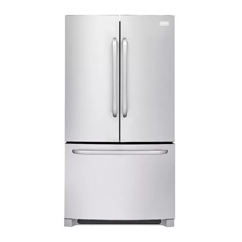
LG LUPXC2386N User manual

MODEL : LUPXC2386N COLOR : PET(ND)
Any reproduction, duplication, distribution (including by way of email, facsimile or other electronic means), publication,
modication, copying or transmission of this Service Manual is STRICTLY PROHIBITED unless you have obtained the
prior written consent of the LG Electronics entity from which you received this Service Manual. The material covered by
this prohibition includes, without limitation, any text, graphics or logos in this Service Manual.
Copyright © 2016 - 2017 LG Electronics Inc. All rights reserved. Only training and service purposes.

electrical
SAFETY PRECATUTION ......................................................................................................................................................... 2
1. SPECIFICATIONS ................................................................................................................................................................ 3
2. PARTS IDENTIFICATION..................................................................................................................................................... 4
3. DISASSEMBLY................................................................................................................................................................ 5-27
REMOVING AND REPLACING REFRIGERATOR DOORS ..................................................................................................... 5
DOOR ........................................................................................................................................................................................ 6
SUB PCB ................................................................................................................................................................................... 7
REFRIGERATOR LIGHT (TOP) ................................................................................................................................................ 8
MULTI DUCT ............................................................................................................................................................................. 9
DISPLAY REMOVAL ............................................................................................................................................................... 10
ICE CORNER DOOR REPLACEMENT .................................................................................................................................. 11
CAP DUCT MOTOR REPLACEMENT .................................................................................................................................... 11
MODULE FILTER REPLACEMENT ........................................................................................................................................ 12
MODULE FILTER PART REPLACEMENT ............................................................................................................................. 12
HOW TO REMOVE A ICE BIN ................................................................................................................................................ 13
ICEMANER REPLACEMENT .................................................................................................................................................. 13
WATER VALVE DISASSEMBLY METHOD ............................................................................................................................ 14
CAUTION : SEALED SYSTEM REPAIR ................................................................................................................................. 15
HOW TO REMOVE AND REINSTALL THE HOME BAR ........................................................................................................ 16
HOW TO REMOVE AND REINSTALL THE HOME BAR DOOR ............................................................................................ 17
HOW TO REMOVE AND REINSTALL THE DOOR FOAM ASSEMBLY, REFRIGERATOR .................................................. 18
HOW TO DISASSEMBLE THE CASE HOME BAR ................................................................................................................ 19
HOW TO CHANGE REED S/W ......................................................................................................................................... 20-21
CHANGE OF DISASSEMBLING METHOD FOR THE CENTER FRONT-ASSEMBLY OF THE FREEZER ..................... 22-23
HOW TO DISASSEMBLE GRILL-ASSEMBLY AND FAN....................................................................................................... 24
DOOR ALIGNMENT ................................................................................................................................................................ 25
FAN AND MOTOR ............................................................................................................................................................. 25-26
HOW TO REPLACE THE BLUETOOTH SPEAKER ............................................................................................................... 27
4.COMPRESSOR.................................................................................................................................................................... 28
5. CIRCUIT DIAGRAM............................................................................................................................................................ 29
6. TROUBLESHOOTING........................................................................................................................................................ 31
7. PCB PICTURE ............................................................................................................................................................... 32-33
8. TROUBLESHOOTING................................................................................................................................................... 34-67
9. COMPRESSOR TROUBLESHOOTING........................................................................................................................ 68-78
10.ICEMAKER OPERATING METHOD AND TROUBLESHOOTING.............................................................................. 79-81
11.MICOM FUNCTION....................................................................................................................................................... 82-88
12.EXPLODED VIEW & REPLACEMENT PARTS LIST................................................................................................... 89-97
Copyright © 2016 - 2017 LG Electronics Inc. All rights
reserved. Only training and service purposes.
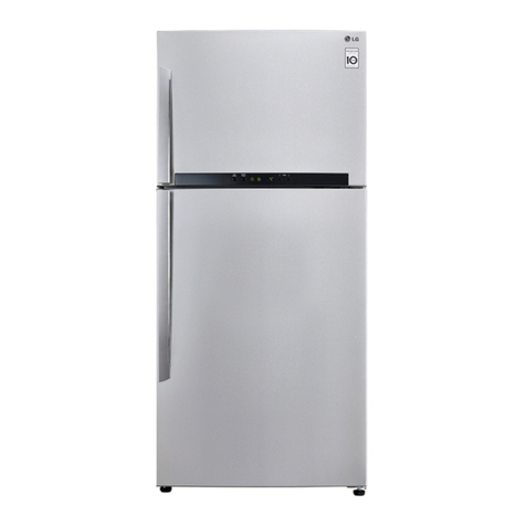
1-1 LUPXC2386N
DOOR DESIGN
DIMENSIONS (inches)
NET WEIGHT (pounds)
COOLING SYSTEM
TEMPERATURE CONTROL
DEFROSTING SYSTEM
DOOR FINISH
HANDLE TYPE
INNER CASE
INSULATION
ITEMS
Side Rounded
35 7/8 X 29 5/8 X 70 1/4(W X D X H) , 22.8cu.ft
430lb (195kg)
Fan Cooling
Micom Control
Full Automatic
Heater Defrost
PET(Non Direction)
Pocket
ABS Resin
Polyurethane Foam
SPECIFICATIONS
30.8 cu.ft.
VEGETABLE TRAY
COMPRESSOR
EVAPORATOR
CONDENSER
REFRIGERANT
LUBRICATING OIL
DEFROSTING DEVICE
ITEMS
Clear Drawer Type
R 134a 175g(6.17oz)
Fin Tube Type
Spiral Condenser (Fe)
R 134a 175g(6.17oz)
ISO10 (280ml)
SHEATH HEATER
LED Module
LED Module
SPECIFICATIONS
LAMP REFRIGERATOR
FREEZER
DIMENSIONS
Description
Front View
Plane View
35 7/8
40 1/8
24 1/2
27 1/2
29 1/2
29 1/2
42 7/8
68 7/8
70 1/4
LUPXC2386N
Width
Depth
Height
Width (A)
When opening door by 90 (including handle/button) (B)
Case (including back handle) (C)
After disassembling door (including hinge, L) (D)
Including door (not including handle) (E)
Including handle button (F)
When opening door by 90 (G)
Cabinit (H)
Including door (K)
J

LED Interior Lamp
The interior lamps light up
the inside of the refrigerator.
Adjustable Refrigerator Shelf
The shelves in yourrefrigerator are adjustable
to meet your individual storage needs.
Refrigerator
Bin
Crisper
Freezer Bin
Container
Pantry
Freezer
Drawer
Freezer
Drawer
Indoor Ice Bin
Icecubes are
automatically
produced.
Door-in-Door™
Condiment Bin
Crisper
Freezer Bin

▶Left Door - FIG.2 / Right Door - FIG.3
1. Disconnect the water supply tube by pushing sleeve.(Left Door only)
2. Open the door. Remove the hinge cover screw and lift the hingecover.
3. Disconnect the door switch wire harness and remove the hingecover.
4. Pull out the tube.
5. Remove the grounding screw.
6. Disconnect the wire harnesses.
7. Rotate hinge lever (left door: counterclockwise; right door:clockwise).
8. Lift the door up from the middle hinge pin and remove the door.
9. Place the door, inside facing up, on a non-scratching surface.
10. To replace the doors, reverse the door removal instructions.
- When lifting hinge free from the latch, be careful that the door not fall forward.
- Before lifting off and removing the refrigerator doors they should be opened to a 90 degree angle.
- Re-install the doors in the same manner they were removed. The door should be placed on the
hinge pin at a 90 degree angle.
- Before assembling the top hinge, check that the doors close properly
CAUTION
Hinge Cover
Wire
Harness
Ground screw
Top hinge
Water Supply Tube
Hinge Lever Latch
Hinge lever
Hinge Cover
Top hinge
Hinge Lever Latch
Hinge lever

1. Remove gasket
Remove the gasket from gasket channel at doorliner as
shown in the illustration below.
3-2 DOOR
Mullion Removal
1. Remove 2 screws.
Door Gasket Removal
2. Lift mullion up carefully.
3. Disconnect wire harness.
Door Gasket Replacement
1. Insert gasket into channel
Insert and press gasket into channels at doorliner.
2. Insert mullion into channel.
Insert the mullion into channel at door as shown below.
Mullion Replacement
1. Connect wire harness
.
3. Assemble 2 screws.
Gasket
Gasket
Channel

b
b
Location of Sub PCB

- 8 -
1. Front side shape 2-1. Using a thin rod, remove Cap.
2-2. Disassemble front screw
3. Using a thin rod,
disassemble multi duct cover
4. Disassemble housing 5. Front shape after remove
multi duct cover.
6. Disassemble housing and front screw.
7.. Disassemble multi duct. 8. Front shape after
remove multi duct
4

- 9 -
1. Insert a tool into the service hole
2. Pull the tool to disassemble the display
3. Try both service hole until the display being separated.
4. Separate the lead wires.
6. Separate from the display cover.
5. Unscrew the screw on the back of the
display, which is separated from the door,
with a driver
7. Assemble the display in an inverse order
DISPLAY REMOVAL
5
5GTXKEG*QNG

- 10 -
3-6 3-11 ICEMAKER REPLACEMENT
1) Remove 3 screws marked in the picture below.
2) Grasp the bottom of motor cover assembly and pull it out
slowly to remove.
3) Disconnect wire harness from wall of compartment.
①② ③
→ →
3-7 3-8
MODULE FILTER REPLACEMENT

- 11 -
①② ③
→ →
3-7 3-8
MODULE FILTER REPLACEMENT
1) Grip the handles, as shown in the picture.
2) Lift the lower part slightly.
3) Take the Ice Bin out slowly.
3-12 HOW TO PLACE ICE BIN IN POSITION
1) Insert the Ice Bin, slightly tilting it to avoid touching the
Icemaker. (Especially, Ice-Detecting Sensor)
Note) Before remove ice bin, put on clean golves for
keeping clean ice bin.
3-9 3-10
MODULE FILTER PART REPLACEMENT

- 12 -
1) Grip the handles, as shown in the picture.
2) Lift the lower part slightly.
3) Take the Ice Bin out slowly.
3-12 HOW TO PLACE ICE BIN IN POSITION
1) Insert the Ice Bin, slightly tilting it to avoid touching the
Icemaker. (Especially, Ice-Detecting Sensor)
Note) Before remove ice bin, put on clean golves for
keeping clean ice bin.
3-9 3-10
MODULE FILTER PART REPLACEMENT
3-6 3-11 ICEMAKER REPLACEMENT
1) Remove 3 screws marked in the picture below.
2) Grasp the bottom of motor cover assembly and pull it out
slowly to remove.
3) Disconnect wire harness from wall of compartment.
1) Grip the handles, as shown in the picture.
2) Lift the lower part slightly.
3) Take the Ice Bin out slowly.
3-12 HOW TO PLACE ICE BIN IN POSITION
1) Insert the Ice Bin, slightly tilting it to avoid touching the
Icemaker. (Especially, Ice-Detecting Sensor)
Note) Before remove ice bin, put on clean golves for
keeping clean ice bin.
3-9 3-10
MODULE FILTER PART REPLACEMENT

- 13 -
3-13

- 14 -
Since 2-way valve controls refrigerant with an inner plastic
damper,defect may occur because the plastic damper
is deteriorated and welding heat is delivered to a pipe during
welding for repair and replacement of the valve
welding part.So perform service in following service method.
1)
Valve welding part service
Replace 2way valve ASSY where refrigerant leakage
occurs at the joint pipe (3,4)connected with the service
valve of valve welding part.
(For unavoidable welding,wrap the body part of valve
with a water towel so that delivery of welding heat is
minimized (100 or less).
2)
Service in replacement of valve (valve failure)
Perform service in the same method as above.
3)
Other cautions
(1) Pipe for capillary tube should be welded through
insertion by 20+3-3mm.(For preventing clogging during
welding)
(2) Take care since inner ejecting objects may be
damaged if falling a valve or giving a strong
shock.(Poor operation and leakage quantity may be increased
due to damage of inner parts.)
insertion of 2-way valve housing,defect or shortage of goods,defective welding.
d
e
Body
F-Room
Dryer side
1)
Valve welding part service
Replace 3way valve ASSY where refrigerant leakage
occurs at the joint pipe (3,45)connected with the Body
service valve of valve welding part. (For unavoidable
welding,wrap the body part of valve with a water towel
so that delivery of welding heat is minimized (100 or
less).
2)
Service in replacement of valve (valve failure)
Perform service in the same method as above.
3)
Other cautions
(1)Pipe for capillary tube should be welded through
insertion by 20+3-3mm.(For preventing clogging during
welding)
(2)Take care since inner ejecting objects may be
damaged if falling a valve or giving a strong
shock.(Poor operation and leakage quantity may be increased due to damage of inner parts.)
(3)Entirely remove and check ice formation which occurred in Eva before or after improvement work for non-
insertion of 3-way valve housing,defect or shortage of goods,defective welding.
d
e
f
Body
F-Room
Dryer side
R-Room
(White)
3-14-2 3-Way Valve Service
Since 3-way valve controls refrigerant with an inner plastic damper,defect may occur because the plastic damper
is deteriorated and welding heat is delivered to a pipe during welding for repair and replacement of the valve
welding part.So perform service in following service method.
(3) Entirely remove and check ice formation which occurred in Eva before or after improvement work for non-
3-14
3-14-1

- 15 -
3-15 HOW TO ASSEMBLE MOVING BASKET
3. Lift up the Basket
4. Insert Moving Cover
(Classify Left & Right)
5. When remove moving cover,
draw cover using L shape rod.
1. Attach Left cover
into the hole
2. Rotate the Basket

- 16 -
3-16. HOW TO ASSEMBLE TOP RR BASKET
1. Rotate the lever.
3-17. HOW TO ASSEMBLE BOTTOM RR BASKET
1. Pull the basket upside.
1. Push the basket until click sound.
3-18. HOW TO DISASSEMBLE BOTTOM RR BASKET

- 17 -
1. Open Home bar Door
.3-1. Remove cover hinge screw.
3-2. Using ‘-’ Driver, remove cover hinge.
3-3. Disconnect housing.
4-1. Lift Home Bar to disassemble with hinge Pin.
4-2 Pull the home bar Left.
2. Draw bottom cover using L shape rod.
16 HOW TO REMOVE AND REINSTALL H/BAR DOOR

- 18 -
3-17 HOW TO REMOVE AND REINSTALL THE RR DOOR
1. Remove the screws from hinge cover.
2. Detach Hinge Cover & Disconnect Housing.
3. Swing the Hinge upper Lever.
4. Open RR Door 90 degree & Lift the door.

- 19 -
3-18-1 Refrigerator Door
1.
2
.
3.
4
.
Push Hook
Push Hook
CHANGE REED S/W
3-18

- 20 -
3-18-2. Freezer Door
ඖFreezer Reed Switch XURemove R/Switch using a thin rod
(or a flat-head screwdriver)
Table of contents
Other LG Refrigerator manuals