Service Manual 7
Installation
Installation
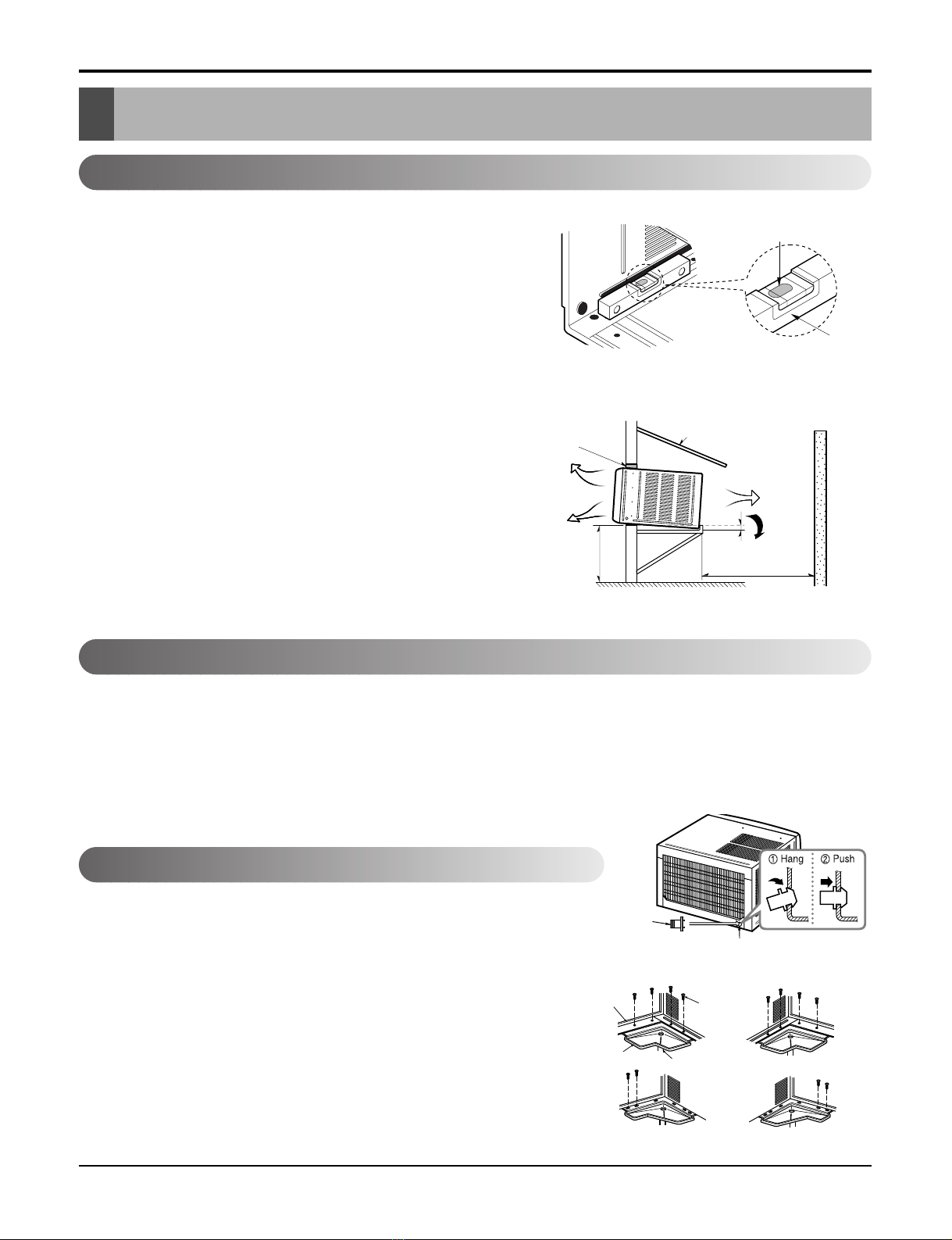
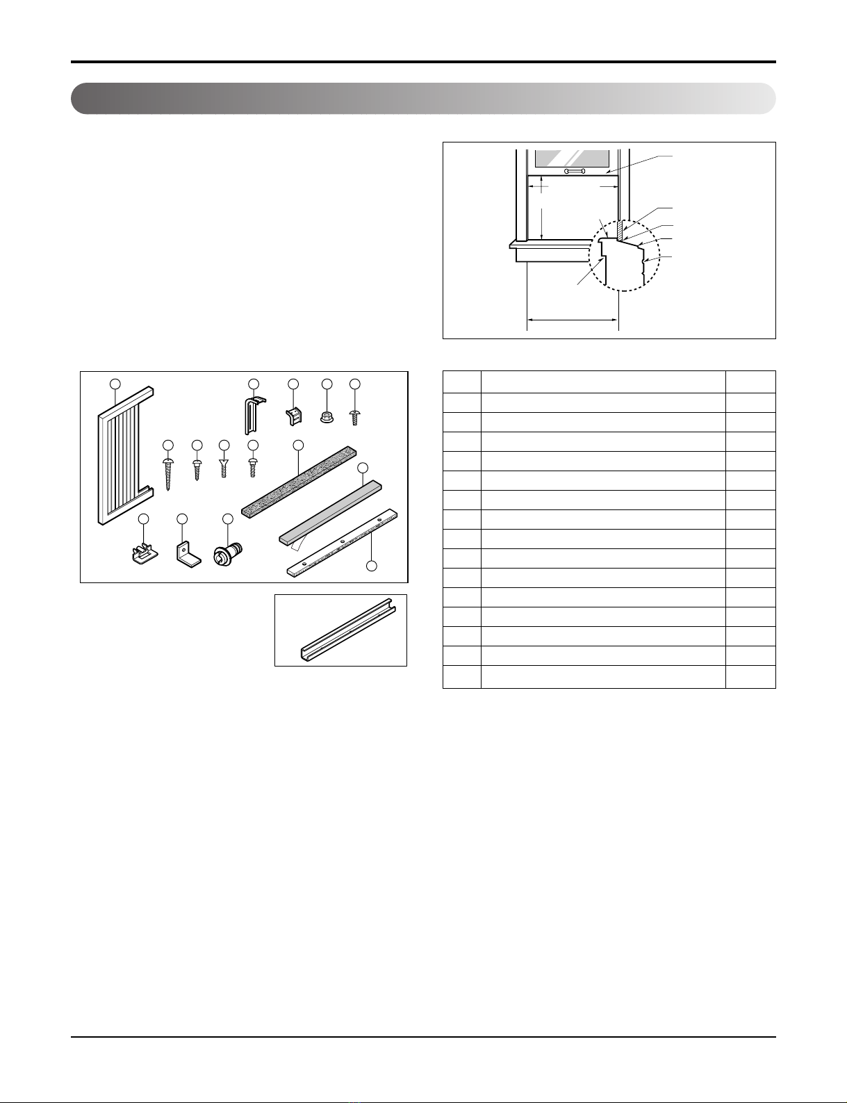
Select the Best Location
Installation Check
How to Secure the Drain Pipe
1. To avoid vibration and noise, make sure the unit is installed
securely and firmly.
2. Install the unit where the sunlight does not shine directly on the
unit.
If the unit receives direct sunlight, build an awning to shade the
cabinet.
3. There should be no obstacle, like a fence, within 20" which
might restrict heat radiation from the condenser.
4. To prevent reducing performance, install the unit so that louvers
of the cabinet are not blocked.
5. Install the unit a little obliquely outward not to leak the con-
densed water into the room (about 1/2" or 1/4 bubble with level).
6. Install the unit with its bottom portion 30~60" above the floor
level.
7. Stuff the foam between the top of the unit and the wall to pre-
vent air and insects from getting into the room.
8. The power cord must be connected to an independent circuit.
The green wire must be grounded.
9. Connect the drain tube to the base pan hole in the rear side if
you need to drain (consult a dealer).
Plastic hose or equivalent may be connected to the drain tube.
The setting conditions must be checked prior to initial starting.
The following items are especially important check points when the installation is finished.
1. Grounding wire (Green or Green and Yellow) is provided in the power cord. The green wire must be grounded.
2. Connect to a single-outlet 15A circuit.
(or 20A circuit for Electric Heater Model)
3. To avoid vibration or noise, make sure the air conditioner is installed securely.
4 Avoid placing furniture or draperies in front of the air inlet and outlet.
In humid weather, excess water may cause the BASE PAN to overflow. To drain
the water, remove the DRAIN CAP and secure the DRAIN PIPE to the rear hole
of the BASE PAN. Press the drain pipe into the hole by pushing down and away
from the fins to avoid injury.
Optional
1. Install the drain pan over the corner of the cabinet where you removed
the plug with 4 (or 2) screws.
2. Connect the drain hose to the outlet located at the bottom of the drain
pan. You can purchase the drain hose or tubing locally to satisfy your
particular needs. (Drain hose is not supplied).
3. Select the most appropriate connection from among the following figures
(by considering the hole of the unit) to fit drain pan to your own unit.
About 1/2"
Over 20"
HEAT
RADIATION
FENCE
AWNING
FOAM
COOLED
AIR
30-60"
Level
1/4 Bubble
Drain pipe
Drain cap
Fig. 4
Fig. 3
Fig. 2
DRAIN
PA N DRAIN HOSE
Fig. 1
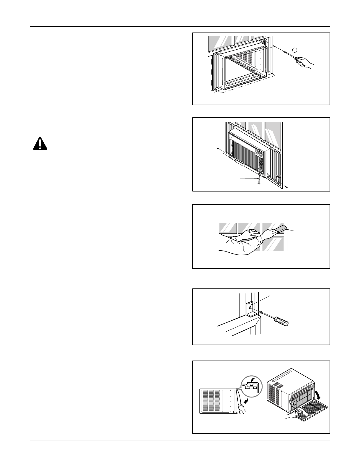
CABINET SCREW
Figure 1