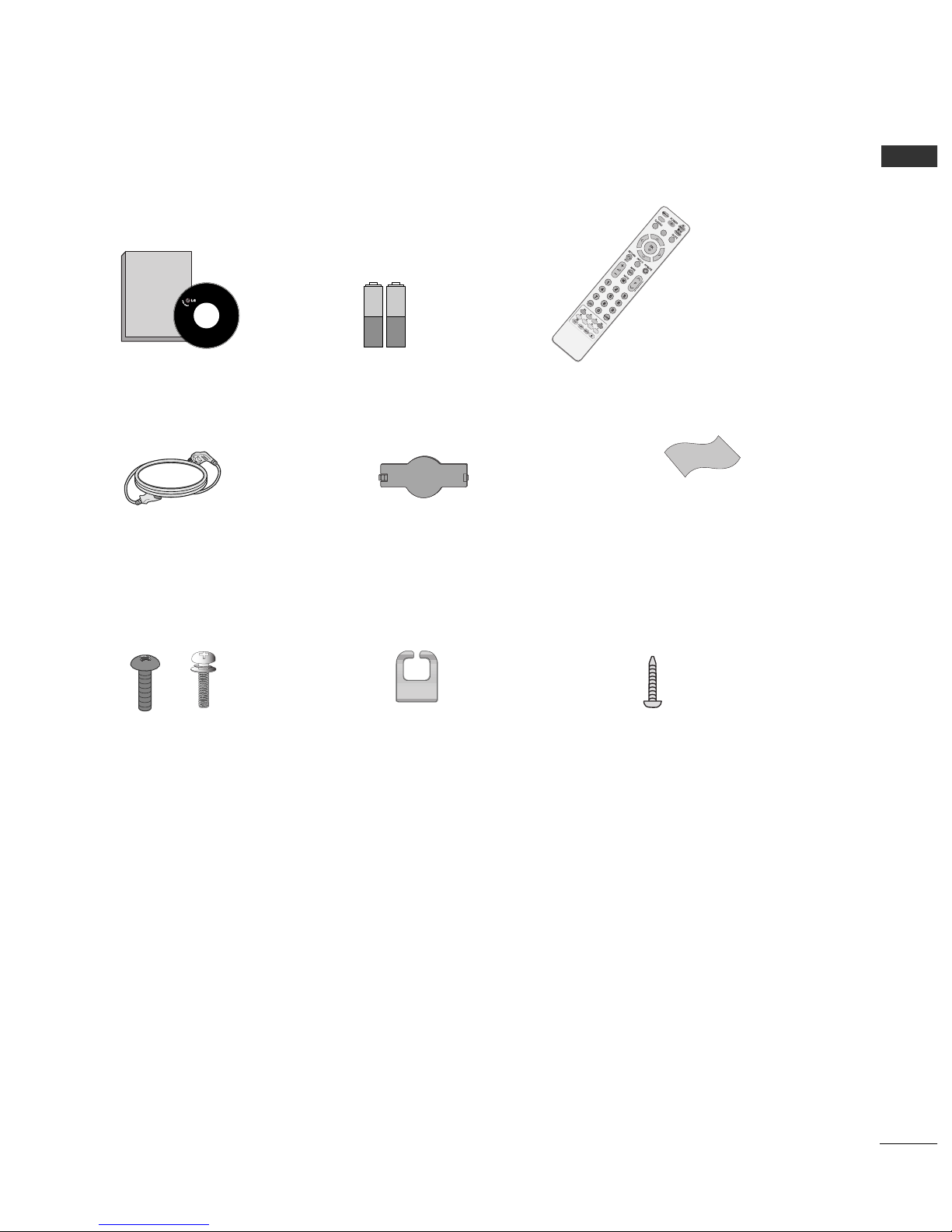
LG 26LG4000 User manual

Please read this manual carefully before operating
your TV.
Retain it for future reference.
Record model number and serial number of the TV.
Refer to the label on the back cover and quote this
information.
To your dealer when requiring service.
LCD TV / DVD Combo
OWNER’S MANUAL
LCD TV MODELS
2266GG4400****
3322GG4400****
Trade Mark of the DVB Digital Video
Broadcasting Project (1991 to 1996)
ENGLISH
IIDD NNuummbbeerr((ss))::5500: 26 G4000 5501: 32 G4000

is a trademark of DVD format/ ogo icensing Corporation.
“ This product incorporates copy protection technology that is protected by U.S. and foreign patents,
including patent nu bers 5,315,448 and 6,836,549, and other intellectual property rights. The use of
Macrovision’s copy protection technology in the product ust be authorized by Macrovision. Reverse
engineering or disasse bly is prohibited. ”

1
ACCESSORIES
ACCESSORIES
Ensure that the following accessories are included with your TV. If an accessory is issing, please contact the
dealer where you purchased the TV.
Owner’s Manual Batteries Remote Control
Power Cord
Owner's
Manual
DISCMENU
MENU/
SETUP
R
O
T
A
T
E
+
R
O
T
A
T
E
-
DISPLAY ZOOM
SUBTITLE
AUDIO
ANGLE
PBC
REPEAT A-B
TITLE MENU
EJECT
RETURN
Protection Cover
Bolts for stand assem ly
(Refer to p.6)
1-screw for stand fixing
(Refer to p.7)
x 4 x 4
Polishing Cloth
Polishing cloth for use on the screen.
ightly wipe any stains or fingerprints on the surface
of the TV with the polishing cloth.
Do not use excessive force. This may cause scratching
or discolouration.
Ca le Management Clip

2
CONTENTS
CONTENTS
ACCESSORIES
. . . . . . . . . . . . . . . . . . . . . . . . . . . . . . . . . . . . . . . . . . . . .
1
PREPARATION
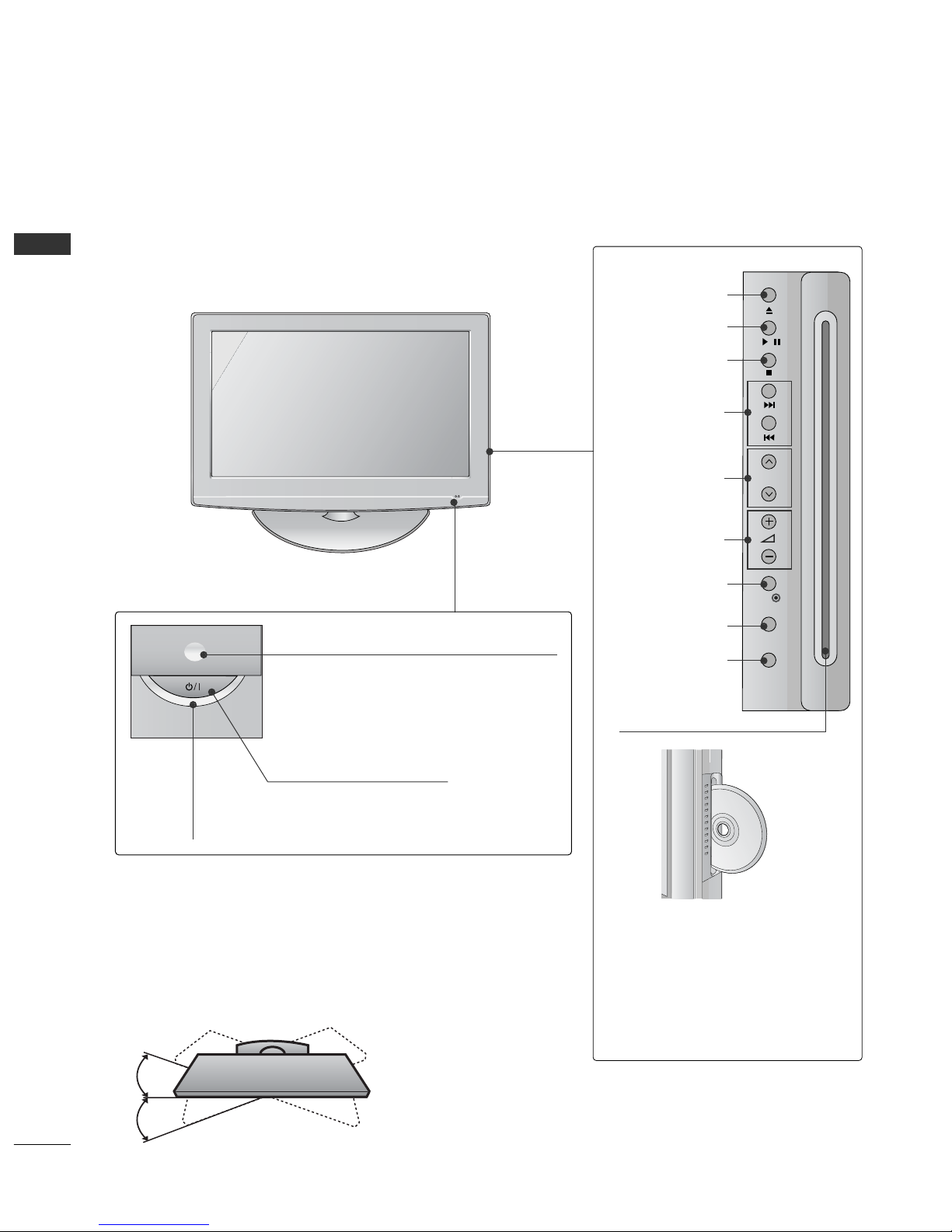
Front Panel Controls . . . . . . . . . . . . . . . . . . . . . . . . 4
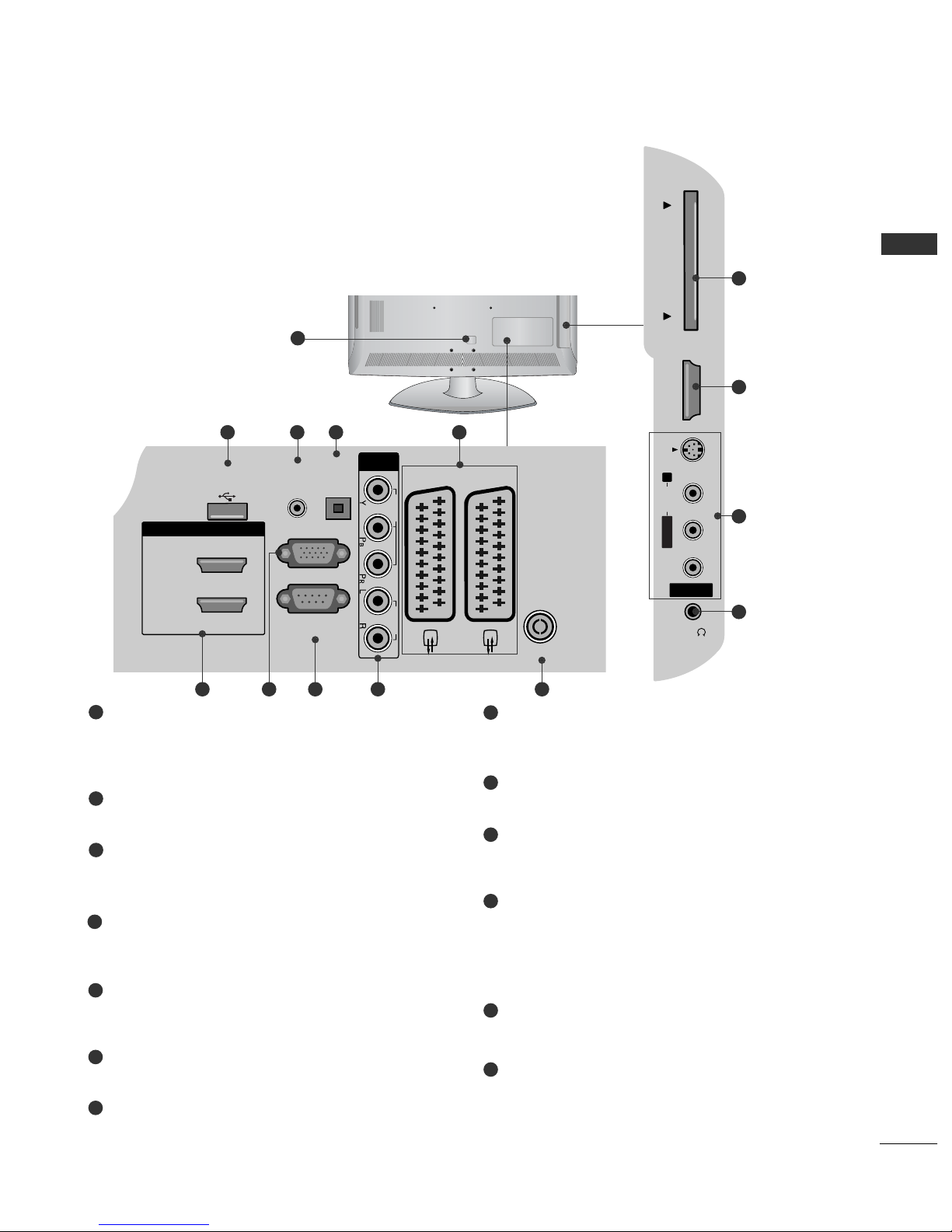
Back Panel Information . . . . . . . . . . . . . . . . . . . . . . 5
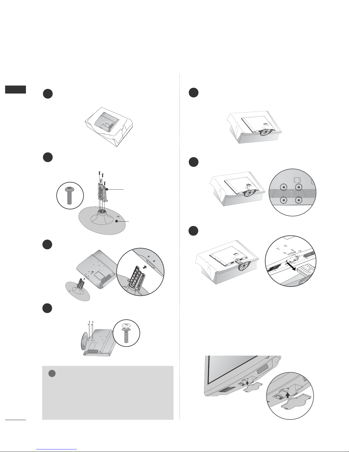
Stand Instruction . . . . . . . . . . . . . . . . . . . . . . . . . . . 6
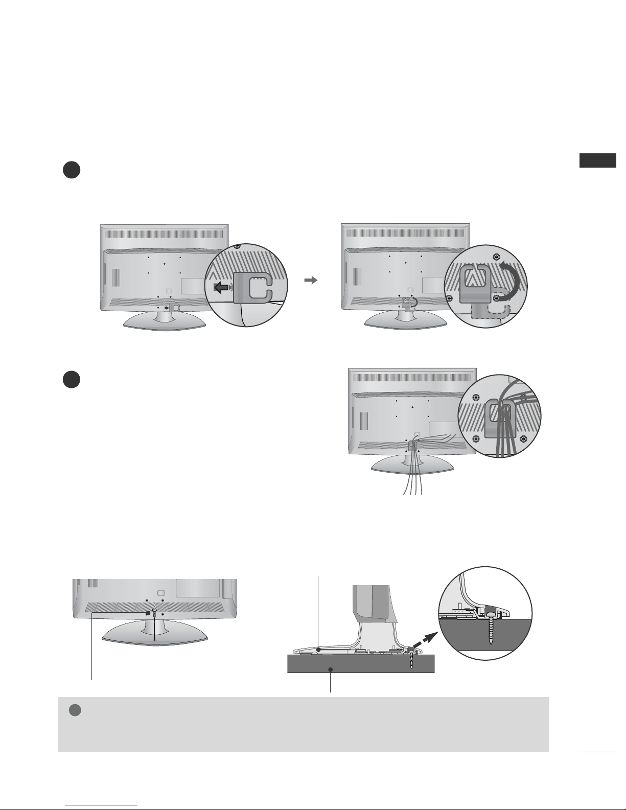
Back Cover for Wire Arrangement . . . . . . . . . . . . . . 7
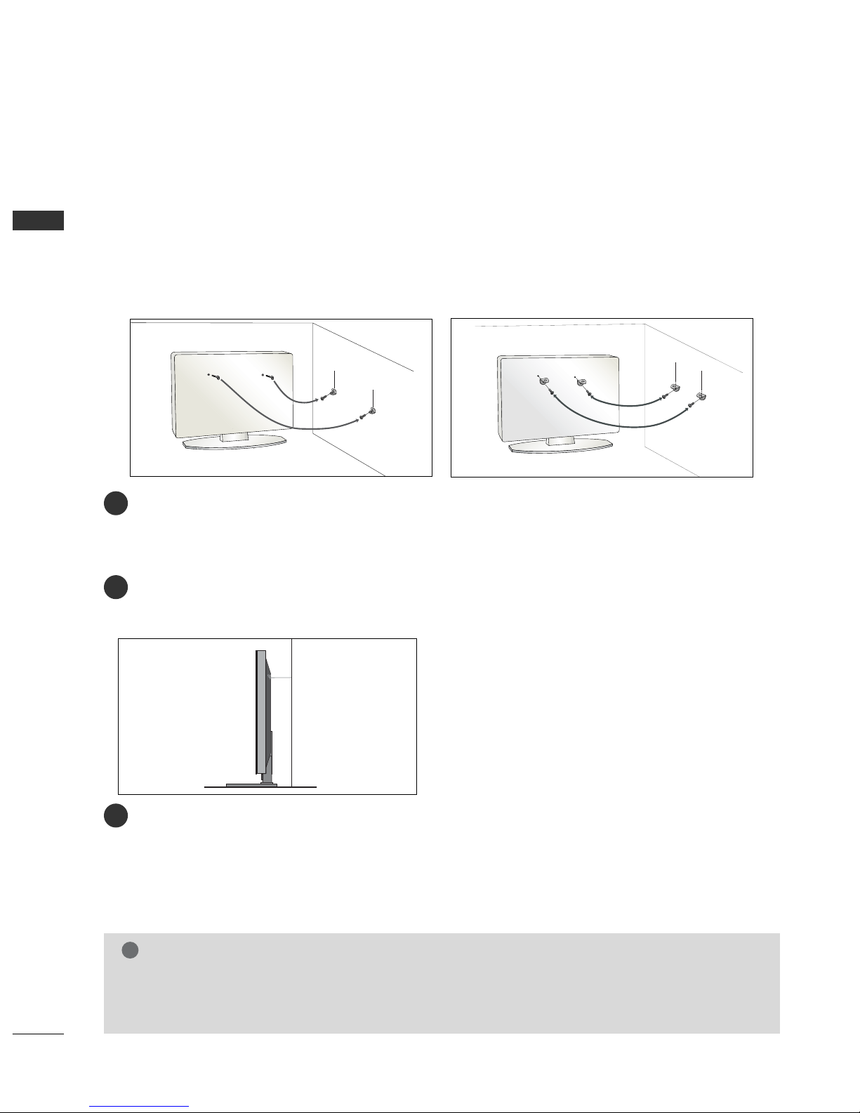
Please set it up carefully so the product
does not fall over . . . . . . . . . . . . . . . . . . . . . . . . . . . 8
Desktop Pedestal Installation . . . . . . . . . . . . . . . . . . 9
Wall Mount: Horizontal Installation . . . . . . . . . . . . . 9
Antenna Connection . . . . . . . . . . . . . . . . . . . . . . . . 10
EXTERNAL EQUIPMENT SETUP
HD Receiver Setup . . . . . . . . . . . . . . . . . . . . . . . . 11
Digital Audio out Setup . . . . . . . . . . . . . . . . . . . . . 12
DVD Setup . . . . . . . . . . . . . . . . . . . . . . . . . . . . . . . . 13
VCR Setup . . . . . . . . . . . . . . . . . . . . . . . . . . . . . . . . 15
Other A/V Source Setup . . . . . . . . . . . . . . . . . . . . . 17
Insertion of CI Module . . . . . . . . . . . . . . . . . . . . . . 18
PC Setup . . . . . . . . . . . . . . . . . . . . . . . . . . . . . . . . . 18
- Screen Setup for PC Mode . . . . . . . . . . . . . . . 21
WATCHING TV / PROGRAMME CONTROL
Remote Control Key Functions . . . . . . . . . . . . . . . . 25
Turning on the TV . . . . . . . . . . . . . . . . . . . . . . . . . . 27
Programme Selection . . . . . . . . . . . . . . . . . . . . . . . 27
Volume Adjustment . . . . . . . . . . . . . . . . . . . . . . . . . 27
Quick Menu . . . . . . . . . . . . . . . . . . . . . . . . . . . . . . . 28
On-Screen Menus Selection and Adjustment . . . . 29
Auto Programme Tuning . . . . . . . . . . . . . . . . . . . . . 30
Manual Programme Tuning (In Digital Mode) . . . . 31
Manual Programme Tuning (In Analogue Mode) . . 32
Programme Edit . . . . . . . . . . . . . . . . . . . . . . . . . . . . 34
Booster (In Digital Mode only) . . . . . . . . . . . . . . . 37
Software Update . . . . . . . . . . . . . . . . . . . . . . . . . . . 38
Diagnostics (In Digital Mode only) . . . . . . . . . . . . 39
CI Information . . . . . . . . . . . . . . . . . . . . . . . . . . . . . 40
Selecting the Programme Table . . . . . . . . . . . . . . . 41
SIMPLINK . . . . . . . . . . . . . . . . . . . . . . . . . . . . . . . . 42
Input Label . . . . . . . . . . . . . . . . . . . . . . . . . . . . . . . 44
AV Mode . . . . . . . . . . . . . . . . . . . . . . . . . . . . . . . . . 45
EPG (ELECTRONIC PROGRAMME
GUIDE) (IN DIGITAL MODE)
Switch On/ Off EPG . . . . . . . . . . . . . . . . . . . . . . . . 46
Select Programme . . . . . . . . . . . . . . . . . . . . . . . . . . 46
Button Function in NOW/NEXT Guide Mode . . . . . 47
Button Function in 8 Day Guide Mode . . . . . . . . . . 47
Button Function in Date Change Mode . . . . . . . . . . 47
Button Function in Extended Description Box . . . . . 48
Button Function in Record/Remind Setting Mode . . 48
Button Function in Schedule List Mode . . . . . . . . . . 48
DVD OPERATION
Notes on Discs . . . . . . . . . . . . . . . . . . . . . . . . . . . . 49
Selecting Language
- Selecting Audio Language . . . . . . . . . . . . . . . . 51
- Selecting Subtitle Language . . . . . . . . . . . . . . 52
- Selecting Disc OSD Language . . . . . . . . . . . . . 53
Parental Control / Ratings
- Parental Control Setup . . . . . . . . . . . . . . . . . . 54
- Changing the password . . . . . . . . . . . . . . . . . . 55
Picture Size Control . . . . . . . . . . . . . . . . . . . . . . . . 56
Digital Audio Output . . . . . . . . . . . . . . . . . . . . . . . 57
Dynamic Range Compression (DRC) . . . . . . . . . . . 58
Playing a DVD or Video CD . . . . . . . . . . . . . . . . . . 59
MP3 Operation . . . . . . . . . . . . . . . . . . . . . . . . . . . . 62
Audio CD Operation . . . . . . . . . . . . . . . . . . . . . . . . 63
JPG File Viewing Options . . . . . . . . . . . . . . . . . . . . 64

3
CONTENTS
PICTURE CONTROL
Picture Size (Aspect Ratio) Control . . . . . . . . . . . . 65
Preset Picture Settings
- Picture Mode-Preset . . . . . . . . . . . . . . . . . . . . 67
-
Auto Colour Tone Control (Warm/Medium/Cool)
. . . . 68
Manual Picture Adjustment
- Picture Mode-User option . . . . . . . . . . . . . . . 69
- Picture Mode-Expert Control . . . . . . . . . . . . 70
Picture Improvement Technology . . . . . . . . . . . . . . . . . 71
Advanced - Film Mode . . . . . . . . . . . . . . . . . . . . . . 72
Advanced - Black(Darkness) Level . . . . . . . . . . . . . 73
Eye Care . . . . . . . . . . . . . . . . . . . . . . . . . . . . . . . . . . 74
Picture Reset . . . . . . . . . . . . . . . . . . . . . . . . . . . . . . 75
SOUND & LANGUAGE CONTROL
Auto Volume Leveler . . . . . . . . . . . . . . . . . . . . . . . . 76
Preset Sound Settings - Sound Mode . . . . . . . . . . 77
Sound Setting Adjustment - User Mode . . . . . . . . . . 78
Balance . . . . . . . . . . . . . . . . . . . . . . . . . . . . . . . . . . . 79
TV Speakers On/ Off Setup . . . . . . . . . . . . . . . . . 80
Selecting Digital Audio Out . . . . . . . . . . . . . . . . . . 81
Audio Reset . . . . . . . . . . . . . . . . . . . . . . . . . . . . . . . 82
I/II
-
Stereo/Dual Reception (In Analogue Mode Only)
. . . . 83
-
NICAM Reception (In Analogue Mode Only) . . . . . . .
84
- Speaker Sound Output Selection . . . . . . . . . . 84
On-Screen Menu Language/Country Selection
. . . . . . . . 85
Language selection (In Digital Mode only) . . . . . . 86
TIME SETTING
Clock Setup . . . . . . . . . . . . . . . . . . . . . . . . . . . . . . . 87
Auto On/ Off Timer Setting . . . . . . . . . . . . . . . . . . 88
Auto Shut-off Setting . . . . . . . . . . . . . . . . . . . . . . . 89
Time Zone Setup . . . . . . . . . . . . . . . . . . . . . . . . . . 90
Sleep Timer Setting . . . . . . . . . . . . . . . . . . . . . . . . . 90
PARENTAL CONTROL / RATINGS
Set Password & Lock System . . . . . . . . . . . . . . . . . 91
Block Programme . . . . . . . . . . . . . . . . . . . . . . . . . . . 92
Parental Control (In Digital Mode only) . . . . . . . . 93
Key Lock . . . . . . . . . . . . . . . . . . . . . . . . . . . . . . . . . 94
TELETEXT
Switch On/ Off . . . . . . . . . . . . . . . . . . . . . . . . . . . . 95
SIMPLE Text . . . . . . . . . . . . . . . . . . . . . . . . . . . . . . . 95
TOP Text . . . . . . . . . . . . . . . . . . . . . . . . . . . . . . . . . 95
FASTEXT . . . . . . . . . . . . . . . . . . . . . . . . . . . . . . . . . 96
Special Teletext Functions . . . . . . . . . . . . . . . . . . . . 96
DIGITAL TELETEXT
Teletext within Digital Service . . . . . . . . . . . . . . . 97
Teletext in Digital Service . . . . . . . . . . . . . . . . . . 97
APPENDIX
Initializing (Reset to original factory setting) . . . . 98
Troubleshooting . . . . . . . . . . . . . . . . . . . . . . . . . . . 99
Maintenance . . . . . . . . . . . . . . . . . . . . . . . . . . . . . . 101
Product Specifications . . . . . . . . . . . . . . . . . . . . . 102
IR Codes . . . . . . . . . . . . . . . . . . . . . . . . . . . . . . . . 103
External Control Device Setup . . . . . . . . . . . . . . 105

4
PREPARATION
PREPARATION
FRONT PANEL CONTROLS
■
Image shown may differ from your TV.
■
If your TV has a protection film attached, remove the film and then wipe the TV with a polishing cloth.
POWER
Power/Standby Indicator
• illuminates red in standby mode.
• illuminates blue when the TV is switched
on.
Note: You can adjust PPoowweerrIInnddiiccaattoorrin
the OPTION menu.
MENU
INPUT
/
P
OK
PROGRAMME
VOLUME
OK
EJECT
PLAY/PAUSE
STOP
SKIP
MENU
INPUT
DDiissccSSlloott::
Insert discs with the label facing
towards the front of the TV. Press
the disc partially into the slot and
the loader will pull the disc from
your hand. Do not force the disc
into the slot.
Remote Control Sensor
Swivel Stand
After installing the TV, you can adjust the TV manually
to the left or right direction by 20 degrees to suit your
viewing position.

5
PREPARATION
RGB IN
(PC)
OPTICAL
DIGITAL
AUDIO OUT
AV 1 AV 2
ANTENNA IN
RS-232C IN
(CONTROL & SERVICE)
AUDIO IN
(RGB/DVI)
HDMI/DVI IN
2
1(DVI)
COMPONENT
IN
VIDEO AUDIO
AV IN 3
H/P
L/ MONO
R
AUDIO
HDMI IN 3 PCMCIS CARD SLOT
VIDEO
S-VIDEO
USB IN
SERVICE ONLY
Power Cord Socket
This TV operates on an AC power. The voltage is
indicated on the Specifications page. Never
attempt to operate the TV on DC power.
RGB/DVI Audio Input
Connect the audio from a PC or DTV.
DIGITAL AUDIO OUT OPTICAL
Connect digital audio from various types of equipment.
Note: In standby mode, these ports do not work.
Euro Scart Socket (AV1/AV2)
Connect scart socket input or output from an
external device to these jacks.
HDMI Input
Connect a HDMI signal to HDMI IN. Or DVI (VIDEO)
signal to HDMI/DVI port with DVI to HDMI cable.
RGB Input
Connect the output from a PC.
RS-232C IN (CONTROL & SERVICE) PORT
Connect to the RS-232C port on a PC.
Component Input
Connect a component video/audio device to
these jacks.
Antenna Input
Connect RF antenna to this jack.
PCMCIA (Personal Computer Memory Card
International Association) Card Slot
(This feature is not available in all countries.)
Audio/Video Input
Connect audio/video output from an external
device to these jacks.
S-Video Input
Connect S-Video out from an S-VIDEO device.
Headphone Socket
Connect the headphone plug to this socket.
SERVICE ONLY PORT
1
2
3
4
5
6
7
8
9
10
11
12
13
R
( )
2
13 43
AV IN 3
H/P
L/MONO
R
AUDIO
AUDIO
HDMI IN 3
HDMI IN 3
PCMCIA CARD SLOT
PCMCIA CARD SLOT
VIDEO
VIDEO
S-VIDEO
95 6 7 8
10
5
11
12
1
BACK PANEL INFORMATION
■
Image shown may differ from your TV.

6
PREPARATION
PREPARATION
STAND INSTRUCTION
■
Image shown may differ from your TV.
Assemble the parts of the SSTTAANNDDBBOODDYY
with CCOOVVEERRBBAASSEEof the TV.
Assemble the TV as shown.
3
Fix the 4 bolts securely using the holes in the
back of the TV.
4
SSTTAANNDDBBOODDYY
CCOOVVEERRBBAASSEE
Carefully place the TV screen side down on a
cushioned surface to protect the screen from
damage.
1
2
INSTALLATION DETACHMENT
Carefully place the TV screen side down on a
cushioned surface to protect the screen from
damage.
1
Loose the bolts from TV.
2
Detach the stand from TV.
3
When installing the wall-mounted unit, use the
protection cover for desk-type stand installation.
Insert the PPRROOTTEECCTTIIOONNCCOOVVEERRinto the TV
until clicking sound.
Not using the desk-type stand
GGWhen assembling the desk type stand, check
whether the bolt is fully tightened. (If not tight-
ened fully, the product can tilt forward after the
product installation.) If you tighten the bolt
with excessive force, the bolt can deviate from
abrasion of the tightening part of the bolt.
NOTE
!

7
PREPARATION
BACK COVER FOR WIRE ARRANGEMENT
■
Image shown may differ from your TV.
Align the hole with the tab on the CCAABBLLEEMMAANNAAGGEEMMEENNTTCCLLIIPP.
Turn the CCAABBLLEEMMAANNAAGGEEMMEENNTTCCLLIIPPas shown.
Note: This cable management clip can be broken by excessive pressure.
Connect the cables as necessary.
To connect additional equipment, see the
EXTERNAL EQUIPMENT SETUP section.
1
2
Attaching the TV to a desk
WARNING
!
GGTo prevent TV from falling over, the TV should be securely attached to the floor/wall per installation
instructions. Tipping, shaking, or rocking the machine may cause injury.
The TV must be attached to desk so it cannot be pulled in a forward/backward direction, potentially causing
injury or damaging the product. Use only an attached screw.
1-Screw
(provided as parts of the product)
Desk
Stand

8
PREPARATION
PREPARATION
PLEASE SET IT UP CAREFULLY SO THE PRODUCT DOES NOT
FALL OVER.
■You should purchase necessary components to fix the TV to the wall on the market.
■Position the TV close to the wall to avoid the possibility of it falling when pushed.
■The instructions shown below are a safer way to set up the TV, which is to fix it to the wall, avoiding the
possibility of it falling forwards if pulled. This will prevent the TV from falling forward and causing injury. This
will also prevent the TV from damage. Ensure that children do not climb or hang from the TV.
NOTE
!
G When moving the TV undo the cords first.
G Use a platform or cabinet strong and large enough to support the size and weight of the TV.
G To use the TV safely make sure that the height of the bracket on the wall and on the TV is the same.
3
1
2
Use the eye-bolts or TV brackets/bolts to fix the TV to the wall as shown in the picture.
(If your TV has bolts in the eyebolts, loosen these bolts.)
* Insert the eye-bolts or TV brackets/bolts and tighten them securely in the upper holes.
Secure the wall brackets with the bolts on the wall. Match the height of the bracket that is mounted on the
wall.
3Use a sturdy rope to tie the TV. It is safer to tie the rope so it becomes horizontal between the wall and the
TV.
2
1
2
1

9
PREPARATION
DESKTOP PEDESTAL INSTALLATION
R
For adequate ventilation allow a clearance of 4” (10cm) all around the TV.
EARTHING
Ensure that you connect the earth wire to prevent possible
electric shock. If grounding methods are not possible, have a
qualified electrician install a separate circuit breaker.
Do not try to earth the TV by connecting it to telephone
wires, lightening rods or gas pipes.
Power Supply
Circuit
breaker
■The TV can be installed in various ways such as on a wall, or on a desktop etc.
■The TV is designed to be mounted horizontally.
4 inches
4 inches 4 inches 4 inches
WALL MOUNT: HORIZONTAL INSTALLATION
For adequate ventilation allow a clearance of 4” (10cm) all around the TV. We recommend that you
use a wall mounting bracket of LG brand when mounting the TV to a wall.
4 inches
4 inches
4 inches 4 inches
4 inches

10
PREPARATION
PREPARATION
AV 1 AV 2
ANTENNA IN
■For optimum picture quality, adjust antenna direction.
■An antenna cable and converter are not supplied.
■To prevent damage do not connect to the mains outlet until all connections are made between the devices.
Multi-family Dwellings/Apartments
(Connect to wall antenna socket)
Single-family Dwellings /Houses
(Connect to wall jack for outdoor antenna)
Outdoor
Antenna
(VHF, UHF)
Wall
Antenna
Socket
RF Coaxial Wire (75 ohm)
ANTENNA CONNECTION
Antenna
UHF
Signal
Amplifier
VHF
■In poor signal areas, to achieve better picture quality it may be necessary to install a signal amplifier to the
antenna as shown above.
■If signal needs to be split for two TVs, use an antenna signal splitter for connection.
R
( )
AV 1 AV 2
ANTENNA IN

11
EXTERNAL EQIPMENT SETUP
EXTERNAL EQUIPMENT SETUP
Connect the video outputs (Y, PB, PR)of the digital set
top box to the CCOOMMPPOONNEENNTTIINNVVIIDDEEOOjacks on the TV.
Connect the audio output of the digital set-top box to
the CCOOMMPPOONNEENNTTIINNAAUUDDIIOOjacks on the TV.
Turn on the digital set-top box.
(Refer to the owner’s manual for the digital set-top box.)
Select CCoommppoonneennttinput source using the IINNPPUUTTbutton
on the remote control.
2
3
4
1
HD RECEIVER SETUP
■To avoid damaging any equipment, never plug in any power cords until you have finished connecting all equipment.
■
Image shown may differ from your TV.
Connecting with a component cable
RGB IN
(PC)
OPTICAL
DIGITAL
AUDIO OUT
AV
RS-232C IN
(CONTROL & SERVICE)
AUDIO IN
(RGB/DVI)
HDMI/DVI IN
2
1(DVI)
COMPONENT
IN
VIDEO AUDIO
USB IN
SERVICE ONLY
12
Signal
480i/576i
480p/576p
720p/1080i
1080 p
Component
Yes
Yes
Yes
Yes
(50/60Hz)
HDMI
No
Yes
Yes
Yes
Connecting a set-top box with an HDMI cable
Connect the HDMI output of the digital set-top box to the
HHDDMMII//DDVVIIIINN11((DDVVII)),HHDDMMII//DDVVIIIINN22or HHDDMMIIIINN
33jack on the TV.
Turn on the digital set-top box.
(Refer to the owner’s manual for the digital set-top box.)
Select HDMI1, HDMI2 or HDMI3 input source using the
IINNPPUUTTbutton on the remote control.
2
3
1
RGB IN
(PC)
OPTICA
DIGITA
AUDIO O
RS-232C IN
(CONTROL & SERVIC
AUDIO IN
(RGB/DVI)
HDMI/DVI IN
2
1(DVI)
HDMI-DTV OUTPUT
USB IN
SERVICE ONLY
1
■This TV can receive Digital RF/Cable signals without an external digital set-top box. However, if you do receive
Digital signals from a digital set-top box or other digital external device, refer to the diagram as shown below.

12
EXTERNAL EQIPMENT SETUP
EXTERNAL EQUIPMENT SETUP
Connect the digital set-top box to HHDDMMII//DDVVIIIINN
11((DDVVII))jack on the TV.
Connect the audio output of the digital set-top box to
the AAUUDDIIOOIINN((RRGGBB//DDVVII))jack on the TV.
Turn on the digital set-top box. (Refer to the owner’s
manual for the digital set-top box.)
Select HDMI 1 input source using the IINNPPUUTTbutton
on the remote control.
2
3
4
1
Connecting with a HDMI to DVI cable
RGB IN
(PC)
OPTICAL
DIGITAL
AUDIO OUT
AV 1
RS-232C IN
(CONTROL & SERVICE)
AUDIO IN
(RGB/DVI)
HDMI/DVI IN
2
1(DVI)
COMPONENT
IN
VIDEO AUDIO
USB IN
SERVICE ONLY
12
DIGITAL AUDIO OUT SETUP
- Sending the TV’s audio signal to external audio equipment via
the Digital Audio Output (Optical) port.
GDo not look into the optical output port. Looking at the
laser beam may damage your vision.
CAUTION
RGB IN
(PC)
OPTICAL
DIGITAL
AUDIO OUT
AV 1 AV
RS-232C IN
(CONTROL & SERVICE)
AUDIO IN
(RGB/DVI)
I/DVI IN
COMPONENT
IN
VIDEO AUDIO
USB IN
SERVICE ONLY
Connect one end of an optical cable to the TV Digital
Audio (Optical)Output port.
Connect the other end of the optical cable to the
digital audio (optical)input on the audio equipment.
Set the “ TV Speaker option - Off ” in the AUDIO
menu. (G pp..8800) Refer to the external audio equipment
instruction manual for operation.
2
3
1
1
2

13
EXTERNAL EQIPMENT SETUP
DVD SETUP
When connecting with a component cable
RGB IN
(PC)
OPTICAL
DIGITAL
AUDIO OUT
AV 1
RS-232C IN
(CONTROL & SERVICE)
AUDIO IN
(RGB/DVI)
HDMI/DVI IN
2
1(DVI)
COMPONENT
IN
VIDEO AUDIO
AV IN 3
H/P
L/ MONO
R
AUDIO
HDMI IN 3 PCMCIA CARD SLOT
VIDEO
S-VIDEO
USB IN
SERVICE ONLY
Component Input ports
To achieve better picture quality, connect a DVD player to
the component input ports as shown below.
Component ports on the TV
YP
BPR
Video output ports
on DVD player
Y
Y
Y
Y
PB
B-Y
Cb
Pb
PR
R-Y
Cr
Pr
Connect the video outputs (Y, PB, PR)of the DVD to the
CCOOMMPPOONNEENNTTIINNVVIIDDEEOOjacks on the TV.
Connect the audio outputs of the DVD to the
CCOOMMPPOONNEENNTTIINNAAUUDDIIOOjacks on the TV.
Turn on the DVD player, insert a DVD.
Select CCoommppoonneennttinput source using the IINNPPUUTTbutton
on the remote control.
Refer to the DVD player's manual for operating instructions.
2
3
4
5
1
1 2
(PC)
OPTICAL
DIGITAL
AUDIO OUT
AV 1 AV 2
ANTENNA IN
C IN
SERVICE)
COMPONENT
IN
VIDEO AUDIO
AV IN 3
H/P
L/ MONO
R
AUDIO
HDMI IN 3 PCMCIA CARD SLOT
VIDEO
S-VIDEO
(R) AUDIO (L)
AUDIO/
VIDEO
Connecting with a Euro Scart cable
Connect the Euro scart socket of the DVD to the AAVV11
Euro scart socket on the TV.
Turn on the DVD player, insert a DVD.
Select AAVV11input source using the IINNPPUUTTbutton on the
remote control.
If connected to AAVV22Euro scart socket, select AAVV22input
source.
Refer to the DVD player's manual for operating instructions.
2
3
4
1
1
NOTE
!
GGAny Euro scart cable used must be signal shielded.

14
EXTERNAL EQIPMENT SETUP
EXTERNAL EQUIPMENT SETUP
RGB IN
(PC)
OPTICAL
DIGITAL
AUDIO OUT
RS-232C IN
(CONTROL & SERVICE)
AUDIO IN
(RGB/DVI)
HDMI/DVI IN
2
1(DVI)
CO
AV IN 3
H/P
L/ MONO
R
AUDIO
HDMI IN 3 PCMCIA CARD SLOT
VIDEO
S-VIDEO
USB IN
SERVICE ONLY
Connecting the HDMI cable
Connect the HDMI output of the DVD to the
HHDDMMII//DDVVIIIINN11((DDVVII)),HHDDMMII//DDVVIIIINN22or HHDDMMII
IINN33jack on the TV.
Select HHDDMMII11, HHDDMMII22or HHDDMMII33input source using
the IINNPPUUTTbutton on the remote control.
Refer to the DVD player's manual for operating instructions.
2
3
1
1
GGThe TV can receive video and audio signals simultaneously
when using a HDMI cable.
GGIf the DVD does not support Auto HDMI, you must set the
output resolution appropriately.
NOTE
!
Connecting with a S-Video cable
AV IN 3
H/P
L/MONO
R
AUDIOAUDIO
HDMI IN 3HDMI IN 3 PCMCIA CARD SLOTPCMCIA CARD SLOT
VIDEOVIDEO
S-VIDEO
L R
S-VIDEOVIDEO
OUTPUT
SWITCH
ANT IN
ANT OUT
Connect the S-VIDEO output of the DVD to the
SS--VVIIDDEEOOinput on the TV.
Connect the audio outputs of the DVD to the AAUUDDIIOO
input jacks on the TV.
Turn on the DVD player, insert a DVD.
Select AV 3 input source using the INPUT button on
the remote control.
Refer to the DVD player's manual for operating
instructions.
2
3
4
5
1
12

15
EXTERNAL EQIPMENT SETUP
VCR SETUP
■To avoid picture noise (interference), allow adequate distance between the VCR and TV.
■If 4:3 picture format is used for an extended period the fixed images on the sides of the screen may remain
visible.
When connecting with a RF Cable
Connect the AANNTTOOUUTTsocket of the VCR to the AANNTTEENNNNAAIINNsocket on the
TV.
Connect the antenna cable to the AANNTTIINNsocket of the VCR.
Press the PLAY button on the VCR and match the appropriate channel between
the TV and VCR for viewing.
1
2
3
RGB IN
(PC)
ANTENNA IN
RS-232C IN
(CONTROL & SERVICE)
MI/DVI IN
AUDIO
AV IN 3
L/ MONO
R
AUDIO
HDMI IN 3 PCMCIA CARD SLOT
VIDEO
S-VIDEO
AV IN 3
L/ MONO
R
AUDIO
HDMI IN 3 PCMCIA CARD SLOT
VIDEO
S-VIDEO
OUTPUT
SWITCH
ANT IN
R
S-VIDEO VIDEO
ANT OUT
L
Wall Jack
Antenna
1
2

16
EXTERNAL EQIPMENT SETUP
EXTERNAL EQUIPMENT SETUP
(PC)
OPTICAL
DIGITAL
UDIO OUT
AV 1 AV 2
ANTENNA IN
IN
ERVICE)
COMPONENT
IN
VIDEO AUDIO
AV IN 3
L/ MONO
R
AUDIO
HDMI IN 3 PCMCIA CARD SLOT
VIDEO
S-VIDEO
(R) AUDIO (L)
AUDIO/
VIDEO
Connecting with a Euro Scart cable
Connect the Euro scart socket of the VCR to the AAVV11
Euro scart socket on the TV.
Insert a video tape into the VCR and press PLAY on
the VCR. (Refer to the VCR owner’s manual.)
Select AAVV11input source using the IINNPPUUTTbutton on
the remote control.
If connected to AAVV22Euro scart socket, select AAVV22
input source.
2
3
4
1
1
NOTE
!
GGAny Euro scart cable used must be signal shielded.
Connecting with a RCA cable
AV IN 3
H/P
L/MONO
R
AUDIOAUDIO
HDMI IN 3HDMI IN 3 PCMCIA CARD SLOTPCMCIA CARD SLOT
VIDEOVIDEO
S-VIDEO
AV IN 3
H/P
L/MONO
R
AUDIO
HDMI IN 3 PCMCIA CARD SLOT
VIDEO
S-VIDEO
LRS-VIDEO
VIDEO
OUTPUT
SWITCH
ANT IN
ANT OUT
Connect the AAUUDDIIOO/VVIIDDEEOOjacks between TV and
VCR. Match the jack colours (Video = yellow, Audio Left
= white, and Audio Right = red)
Insert a video tape into the VCR and press PLAY on
the VCR. (Refer to the VCR owner’s manual.)
Select AV 3 input source using the IINNPPUUTTbutton on
the remote control.
1
2
3
GGIf you have a mono VCR, connect the audio cable from the
VCR to the AAUUDDIIOOLL//MMOONNOOjack of the TV.
NOTE
!

17
EXTERNAL EQIPMENT SETUP
GGIf both S-VIDEO and VIDEO sockets have been connected
to the S-VHS VCR simultaneously, only the S-VIDEO can
be received.
NOTE
!
AV IN 3
H/P
L/MONO
R
AUDIO
HDMI IN 3 PCMCIA CARD SLOT
VIDEO
S-VIDEO
AV IN 3
H/P
L/MONO
R
AUDIOAUDIO
HDMI IN 3HDMI IN 3 PCMCIA CARD SLOTPCMCIA CARD SLOT
VIDEOVIDEO
S-VIDEO
LR
S-VIDEO VIDEO
OUTPUT
SWITCH
ANT IN
ANT OUT
Connect the S-VIDEO output of the VCR to the S -
VIDEO input on the TV. The picture quality is improved;
compared to normal composite (RCA cable) input.
Connect the audio outputs of the VCR to the AUDIO
input jacks on the TV.
Insert a video tape into the VCR and press PLAY on the
VCR. (Refer to the VCR owner’s manual.)
Select AV 3 input source using the IINNPPUUTTbutton on the
remote control.
2
3
4
1
1 2
AV IN 3
H/P
L/MONO
R
AUDIOAUDIO
HDMI IN 3HDMI IN 3 PCMCIA CARD SLOTPCMCIA CARD SLOT
VIDEOVIDEO
S-VIDEO
L R
VIDEO
Connect the AAUUDDIIOO/VVIIDDEEOOjacks between TV and
external equipment. Match the jack colours
. (Video =
yellow, Audio Left = white, and Audio Right = red)
Select AV 3 input source using the IINNPPUUTTbutton on
the remote control.
Operate the corresponding external equipment.
Refer to external equipment operating guide.
2
3
1
1
Camcorder
Video Game Set
Connecting with a S-Video cable
OTHER A/V SOURCE SETUP

18
EXTERNAL EQIPMENT SETUP
EXTERNAL EQUIPMENT SETUP
PC SETUP
This TV provides Plug and Play capability, meaning that the PC adjusts automatically to the TV's settings.
Connecting with a D-sub 15 pin cable
RGB IN
(PC)
OPTICAL
DIGITAL
AUDIO OUT
AV 1 AV
RS-232C IN
(CONTROL & SERVICE)
AUDIO IN
(RGB/DVI)
DMI/DVI IN
COMPONENT
IN
VIDEO AUDIO
USB IN
SERVICE ONLY
RGB OUTPUT
AUDIO
12
4
Connect the RGB output of the PC to the RRGGBBIINN
((PPCC))jack on the TV.
Connect the PC audio output to the AAUUDDIIOOIINN
((RRGGBB//DDVVII))jack on the TV.
Turn on the PC and the TV
Select RRGGBBinput source using the INPUT button on
the remote control.
2
3
1
Insert the CI Module to PPCCMMCCIIAA(Personal Computer
Memory Card International Association) CCAARRDDSSLLOOTT
of TV as shown.
For further information, see p.40.
1
INSERTION OF CI MODULE
H/P
HDMI IN 3HDMI IN 3 PCMCIA CARD SLOTPCMCIA CARD SLOT
AV IN 3
L/MONO
R
AUDIOAUDIO
VIDEOVIDEO
S-VIDEO
TVTV
--TToovviieewwtthheeeennccrryypptteedd((ppaayy))sseerrvviicceessiinnddiiggiittaallTTVV
mmooddee..
--TThhiissffeeaattuurreeiissnnoottaavvaaiillaabblleeiinnaallllccoouunnttrriieess..
1
This manual suits for next models
2
Table of contents
Other LG TV DVD Combo manuals