6.Sub-Brightness adjustment
6-1. Preparation for Adjustment
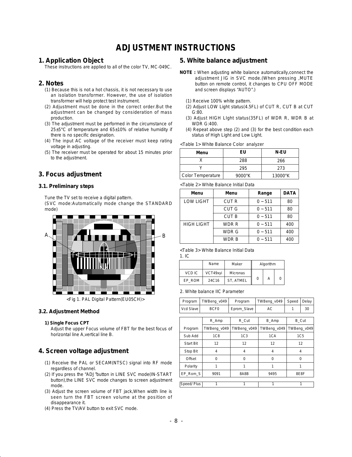
(1) Tune the TV set to receive an Digital pattern(EU05CH).
(2) Deflection setting data adjustment is operate by SVC
communicator.
(3) Enter the Sub-Brightness mode by selection SERVICE1 on
SERVICE MENU after pressing LINE SVC MODE(IN-
START KEY).
(4) Use the CH D,Ekey to select adjustment item.
(5) Use the VOL F,Gkey to increase/decrease data.
6.2 Adjustment
After authorizing a PAL signal, adjust up to the point which
divide one or two volume in Gray Scale of the bottom screen.
7.Deflection setting Data Adjustment
7.1 Adjustment preparation
(1) Tune the TV set to receive an Digital pattern(EU05CH).
(2) Deflection setting data adjustment is operate by SVC
communicator.
(3) Enter the deflection adjustment mode by selection
SERVICE1 on SERVICE MENU after pressing LINE SVC
MODE(IN-START KEY).
(4) Use the CH D,Ekey to select adjustment item.
(5) Use the VOL F,Gkey to increase/decrease data.
7.2 Adjustment
(1) After authorizing a PAL signal, adjust to N50ch .
(2) After adjusting a PAL signal, authorize and notify to
NTSC(US13ch), adjust NTSC if necessary.
* After finishing deflection adjustment,press the ENTER button to
enter or exit in SVC mode.
< Term explanation>
(1) VL(Vertical Linearity) adjustment:
Adjust the top & bottom size of inner circle to be equal.
(2) VA (Vertical Amplitude) adjustment:
Adjust so that the circle of a digital circle pattern should be
located interval of 6~7mm from the effective screen of the
CPT.
(3) SC (S correction) adjustment:
Adjust so that all distance between each lattice width of
top/center/bottom are to be the same.
* Setting the CPT Default(Initial data) value like that, because
it is decide by CPT DY value
(4) VS (Vertical Shift) adjustment:
Adjust so that the geometric vertical center line is in accord
with vertical center line of CPT.
(5) HS(Horizontal Shift) adjustment:
Adjust so that the geometric horizontal center line is in
accord with horizontal center line of CPT.
(6) EW(Hor. Width) adjustment
Adjust until the outmost left and right lattice of received
pattern is accord with 25% of other lattice width.
(7) ET(Trapezoidal) adjustment
Adjust to make the length of top horizontal line same with it
of the bottom horizontal line.
(8) EP(Pin Cushion) adjustment
Adjust so that middle portion of the outermost left and right
vertical line look like parallel with vertical lines of the CPT.
(9) ANGLE adjustment
When you adjust the angle, adjust correctly raster of
left/right screen.
(10) Bow adjustment
After finished EP adjustment, adjust until symmetrized
upper and lower corner of the screen.
(11) UPCOR/LOCOR(Upper/Lower Corner) adjustment
After finished EP adjustment,adjust vertical line of left-top,
right-top, left-bottom, right-bottom of screen to the best
straight line.
8. How to inspect condition of a transmission
and reception in FM TRANSMITTER
MODEL.
- FM TRANSMITTER's efficiency inspections is executed to a
finished in a final inspection phase.
-FM TRANSMITTER is a function which receives voice-signal
by an exclusive remote control and earphone, transmits a
FM through transmitter of inner part in MICOM BOARD to TV
sound(MONITOR OUTPUT)
- If the received frequency which set up in OSD is being tuned
without using an exclusive remote control ,it is available to
receive in a general FM receiver.
(1) Execute in channel generating voice-signal.
(2) Select a transmitted frequency in MENU OSD.
MENU -> SOUND -> TRANSMITTER
-> Select frequency(87.7MHZ)
(3) A received frequency in an exclusive remote control or
received FM Radio is tuned by 87.7MHz which is same as
frequency in OSD.
(4) Check out whether a signal generating to MAIN SPEAKER
generates in earphone or receiver or not.
(5) There is no alternation and setting of adjusted DATA in the
process of inspecting FM TX.
- 9 -
<CAUTION> W/B Program “Twbeng_v049”
- W/B adjustment after Cutoff
: Instart -> adj. -> mute(cutoff)-> tv/av(wb)
Release key is EXIT key
- W/B adjustment
: Instart -> mute(cpuoff)
Release key is TV/AV key
Menu
VS
VA
VL
SC
HS
-512~511
-512~511
-512~511
-512~511
32~2047
150
-12
140
6
100
140
-12
140
6
123
Variable range N50Hz(PAL)
FLAT 21” N60Hz(NTSC)
FLAT 21”
<Table 4> Initial value of deflection setting