LG RU-27FB30C Installation guide

Internet Home Page : http://www.lgcommercial.com
P/N:3828VA0524A b(FCN Chassis)
Installation and Operating Guide Warranty
table of contents page 5
Model Number RU-27FB30C
Please read this manual carefully before operating your set.
Retain it for future reference.
Record model number and serial number of the set.
See the label attached on the back cover and quote this
information to your dealer when you require service.
RU-27FB31C

This reminder is provided to call the cable TV system installer’s attention to Article 820-40 of the
National Electric Code (U.S.A.). The code provides guidelines for proper grounding and, in particular,
specifies that the cable ground shall be connected to the grounding system of the building, as close to
the point of the cable entry as practical.
REGULATORY INFORMATION:
This equipment has been tested and found to comply with the limits for a Class B digital device,
pursuant to Part 15 of the FCC Rules. These limits are designed to provide reasonable protection
against harmful interference when the equipment is operated in a residential installation. This
equipment generates, uses and can radiate radio frequency energy and, if not installed and used in
accordance with the instruction manual, may cause harmful interference to radio communications.
However, there is no guarantee that interference will not occur in a particular installation. If this
equipment does cause harmful interference to radio or television reception, which can be determined
by turning the equipment off and on, the user is encouraged to try to correct the interference by one or
more of the following Measures:
• Reorient or relocate the receiving antenna.
• Increase the separation between the equipment and receiver.
• Connect the equipment into an outlet on a circuit different from that to which the receiver is
connected.
• Consult the dealer or an experienced radio/TV technician for help.
CAUTION:
Do not attempt to modify this product in any way without written authorization from LG Electronics
Corporation. Unauthorized modification could void the user’s authority to operate this product.
COMPLIANCE:
The responsible party for this product’s compliance is:
LG Electronics U.S.A., Inc. 1000 SylvanAvenue, Englewood Cliffs, NJ 07632. 1-201-816-2000
TO REDUCE THE RISK OF ELECTRIC SHOCK DO NOT REMOVE COVER (OR BACK). NO
USER SERVICEABLE PARTS INSIDE.
REFER TO QUALIFIED SERVICE PERSONNEL.
The lightning flash with arrowhead symbol, within an equilateral triangle, is intended to alert the
user to the presence of uninsulated “dangerous voltage” within the product’s enclosure that may
be of sufficient magnitude to constitute a risk of electric shock to persons.
The exclamation point within an equilateral triangle is intended to alert the user to the presence
of important operating and maintenance (servicing) instructions in the literature accompanying
the appliance.
TO PREVENT FIRE OR SHOCK HAZARDS, DO NOT EXPOSE THIS PRODUCT TO RAIN OR MOISTURE.
WARNING:
WARNING:
CAUTION: To prevent electric shock, match wide blade of plug to wide slot, fully insert.
ATTENTION: Pour éviter les chocs électriques, introduire la lame la plus large de la fiche
dans la borne correspondante de la prise et pousser jusqu’au fond.
NOTE TO CABLE/TV INSTALLER:
POWER CORD POLARIZATION:
RECORD THE MODEL NUMBER
The serial number of this Color TV is located
on the back of the cabinet. For future
reference, we suggest that you record the
serial number here:
MODEL NO. RU-27FB30C/RU-27FB31C
SERIAL NO._________________________
For Customer Support/Service please call:
1-888-865-3026
www.lgcommercial.com
RISK OF ELECTRIC
SHOCK
WARNING
© Copyright 2005LG Electronics Corporation
2-WIRE COMM-WARN B-2/02

IMPORTANT SAFETY INSTRUCTIONS
Important safeguards for you and your new product.
PORTABLE CART WARNING
Page 3
Your product has been manufactured and tested with safety in mind. However, improper use can result in potential
electrical shock or fire hazards. To avoid defeating the safeguards that have been built into the new product, please
read and observe the following safety points when installing and using the new product, and save them for future
reference.
Observing the simple precautions discussed in this guide can help get and enjoy many years of safe operation that
are built into your new product.
This product complies with all applicable U.S. Federal safety requirements, and those of the Canadian Standards
Association.
1. Read Instructions
All the safety and operating instructions should be read
before the product is operated.
2. Follow Instructions
All operating and use instructions should be followed.
3. Retain Instructions
The safety and operating instructions should be
retained for future reference.
4. Heed Warnings
All warnings on the product and in the operating
instructions should be adhered to.
5. Cleaning
Unplug this product from the wall outlet before cleaning.
Do not use liquid cleaners or aerosol cleaners. Use a
damp cloth for cleaning.
6. Water and Moisture
Do not use this product near water for example, near a
bath tub, wash bowl, kitchen sink, or laundry tub, in a
wet basement, or near a swimming pool.
7. Accessories, Carts, and Stands
Do not place this product on a slippery or tilted surface,
or on an unstable cart, stand, tripod, bracket, or table.
The product may slide or fall, causing serious injury to a
child or adult, and serious damage to the product. Use
only with a cart, stand, tripod, bracket, or table
recommended by the manufacturer, or sold with the
product. Any mounting of the product should follow the
manufacturer’s instructions, and should use a mounting
accessory recommended by the manufacturer.
8. Transporting Product
A product and cart combination should be moved with
care.
Quick stops, excessive force, and uneven surfaces may
cause the product and cart combination to overturn.
9. Attachments
Do not use attachments not recommended by the
product manufacturer as they may cause hazards.
10. Ventilation
Slots and openings in the cabinet are provided for
ventilation and to ensure reliable operation of the
product and to protect it from overheating, and these
openings must not be blocked or covered. The
openings should never be blocked by placing the
product on a bed, sofa, rug, or other similar surface.
This product should not be placed in a built-in
installation such as a bookcase or rack unless proper
ventilation is provided or the manufacturer’s
instructions have been adhered to.
11. Power Sources
This product should be operated only from the type of
power source indicated on the marking label. If you are
not sure of the type of power supply to your home,
consult your product dealer or local power company.
For products intended to operate from battery power, or
other sources, refer to the operating instructions.
12. Power Cord Polarization
This product is equipped with a polarized alternating-
current power plug (a plug having on blade wider than
the other). This plug will fit into the power outlet only
one way. This is a safety feature. If you are unable to
insert the plug fully into the outlet, try reversing the plug.
If the plug still fail to fit, contact your electrician to
replace your obsolete outlet. Do not defeat the safety
purpose of the polarized plug.
13. Power Cord Protection
Power-supply cords should be routed so that they are
not likely to be walked on or pinched by items placed
upon or against them, paying particular attention to
cords at plugs, convenience receptacles, and the point
where they exit from the product.
14. Outdoor Antenna Grounding
If an outside antenna or cable system is connected to
the product, be sure the antenna or cable system is
grounded so as to provide some protection against
voltage surges and built-up static charges.Article 810 of
the National Electrical Code (U.S.A.), ANSI/ NFPA 70
provides information with regard to proper grounding of
the mast and supporting structure, grounding of the
lead-in wire to an antenna discharge unit, size of
grounding conductors, location of antenna-discharge
unit, connection to grounding electrodes, and
requirements for the grounding electrode.
(Continued on next page)

Example of Grounding According to National
Electrical Code Instructions
15. Lightning
For added protection for this product (receiver)
during a lightning storm, or when it is left unattended
and unused for long periods of time, unplug it from
the wall outlet and disconnect the antenna or cable
system. This will prevent damage to the product
due to lightning and power-line Surges.
16. Power Lines
An outside antenna system should not be located in
the vicinity of overhead power lines or other electric
light or power circuits, or where it can fall into such
power lines or circuits. When installing an outside
antenna system, extreme care should be taken to
keep from touching such power lines or circuits as
contact with them might be fatal.
17. Overloading
Do not overload wall outlets and extension cords as
this can result in a risk of fire or electric shock.
18. Object and Liquid Entry
Never push objects of any kind into this product
through openings as they may touch dangerous
voltage points or short-out parts that could result in
a fire or electric shock.
Never spill liquid of any kind on the product.
19. Servicing
Do not attempt to service this product yourself as
opening or removing covers may expose you to
dangerous voltage or other hazards. Refer all
servicing to qualified service personnel.
20. Damage Requiring Service
Unplug this product from the wall outlet and refer
servicing to qualified service personnel under the
following conditions:
a. If the power-supply cord or plug is damaged.
b. If liquid has been spilled, or objects have fallen
into the product.
c. If the product has been exposed to rain or water.
d. Following the operating instructions. Adjust only
those controls that are covered by the operating
instructions as an improper adjustment of other
controls may result in damage and will often require
extensive work by a qualified technician to restore
the product to its normal operation.
e. If the product has been dropped or the cabinet
has been damaged.
f. If the product exhibits a distinct change in
performance.
21. Replacement Parts
When replacement parts are required, be sure the
service technician has used replacement parts
specified by the manufacturer or have the same
characteristics as the original part. Unauthorized
substitutions may result in fire, electric shock, or
other hazards.
22. Safety Check
Upon completion of any service or repairs to this
product, ask the service technician to perform
safety checks to determine that the product is in
proper operating condition.
23. Wall or Ceiling Mounting
The product should be mounted to a wall or ceiling
only as recommended by the manufacturer. The
product may slide or fall, causing serious injury to a
child or adult, and serious damage to the product.
24. Heat
The product should be situated away from heat
sources such as radiators, heat registers, stoves, or
other products (including amplifiers) that produce
heat.
25. CAUTION concerning the Power Cord:
Most appliances recommend they be placed upon a
dedicated circuit; that is, a single outlet circuit which
powers only that appliance and has no additional
outlets or branch circuits. Check the specification
page of this owner’s manual to be certain.
Do not overload wall outlets. Overloaded wall
outlets, loose or damaged wall outlets, extension
cords, frayed power cords, or damaged or cracked
wire insulation are dangerous. Any of these
conditions could result in electric shock or fire.
Periodically examine the cord of your appliance,
and if its appearance indicates damage or
deterioration, unplug it, discontinue use of the
appliance, and have the cord replaced with an exact
replacement part by an authorized servicer.
Protect the power cord from physical or mechanical
abuse, such as being twisted, kinked, pinched,
closed in a door, or walked upon. Pay particular
attention to plugs, wall outlets, and the point where
the cord exits the appliance.
26. Outdoor use Marking
WARNING - To reduce the risk of fire or electric
shock, do not expose this appliance to rain or
moisture.
27. Wet Location Marking
Apparatus shall not be exposed to dripping or
splashing and no objects filled with liquids, such as
vases, shall be placed on the apparatus.
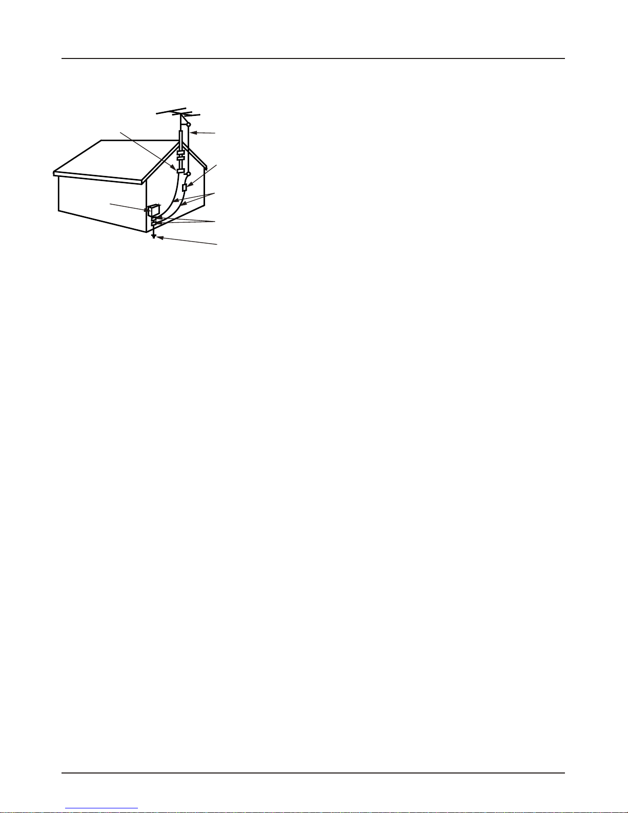
Antenna Lead in Wire
Antenna Discharge
Unit (NEC) Section
810-20
Grounding Conductor
(NEC Section 810-21)
Ground Clamps
Power Service
Grounding Electrode
SyStem (NEC Art 250,
Part H)
IMPORTANT SAFETY INSTRUCTIONS
(Continued from previous page)
Page 4
NEC - National Electrical Code
Ground Clamp
Electric Service
Equipment

Safety Warnings 2
Important Safety Instructions 3 - 4
Table of Contents 5
SC652LG User remote control 6
Optional LP702 Installer’s remote control 7
Connections/Installation Overview 8
Step 1. TV Connections
TV/VCR/Cable Box/and other Equipment Hookup
TV Hook up Directory 9
Antenna 10
Cable service 11
Antenna with VCR 12
Cable service with VCR 13
Additional Equipment Hookup
S-Video VCR/DVD etc 14
Component Video 15
External Amplifier (Audio Out [Matrix] hook up)16
Step 2. TV Reception Set Up & Channel Search
Auto Program: Select Antenna, or Cable service
and start the channel search 17
Front Panel Controls/Source Inputs 18
Picture/Sound Source Selection 19
Source Menu 20
On-Screen Menus/Displays Overview 21
Other Menus and On-Screen Displays
Sleep Timer menu 22
Channel/Time/Audio Display 22
Purchase the Optional Installer’s Remote and Clone Programmer
To perform a normal installation set up, you need an installer’s remote such as the LP702, and the LT2000 Quickset II
Clone Programmer—both are shown and described in later sections. The installer remote allows access to the Installer
and User menus. The LT2000 Quickset II Clone Programmer is used to duplicate a LG TV’s setup and install it on
another identical LG TV. See your LG Dealer.
Note: Design and specifications are subject to change without prior notice.
TABLE OF CONTENTS
Page 5
Use this page as a reference for finding the pages or sections to go to and set up the
Tv’s features for the end user.
Do Step 1. Hook up TV to source equipment
Do Step 2. Reception Setup and Channel Search
Do Step 3. Customize the TVs features for the end user
See the Installer’s menus for TV operational features set up
Volume Display 22
Closed Captions menu 22
Ch Preview menu 22
Ghost Channel Display 22
Alarm menu 22
Step 3. Customize the TV’s Features
Setup Menu (Starts with page 18, Auto Program)
Add/Del/Blank 23
Channel Labels (Preset and Custom) 24 - 25
Source Name 26
Clock Setup (Auto/Manual) 27
Timer Setup (On/Off Timers) 28
Captions (Caption/Text Setup) 29
Tilt 30
Degauss 31
Language 32
Audio Menu 33
Video Menu 34
Parental Control Menu 35 - 38
Installer Menus 39 - 46
LT2000 Quickset II Clone Programmer 47 - 49
Clone Selection Menu Choices 50
Troubleshooting 51 - 53
Maintenance 54
Glossary 55
Warranty Back Cover

SC652LG User Remote Control
Page 6
POWER
Turns TV On or Off
Remote Control part number
SC652LG
6710V00108B
FLASHBK (FLASHBACK)
Returns to the last channel viewed.
.
.
A list of the keys on the SC652LG user’s remote supplied with the TV and their functions.
123
546
7
0
8
ENTER
9
POWER
H
FLS BK
UM T E
V OL UME
CHA NELN
TIMER ALARM
CH PREVIEW
CC
-+
-
+
CC (CLOSED CAPTIONING)
Press to access
closed options.
Press ENTER to exit..
VOLUME DOWN/UP
Adjusts the sound level.
NUMBER KEYPAD
Select channels directly; enter
channel numbers and press
(SLEEP) TIMER
Press repeatedly to choose a
TV turn-off time up to 4-hours.
Use to set AM/PM on the
Alarm menu.
MUTE
Turns sound Off and On, while the
picture remains.
CHANNEL (UP/DOWN)
Scroll through available channels,
and the Video Channel (Audio/Video
source).
ENTER
Press to view the
Channel/Time/Audio
display or to remove any on-screen
display or menu.
ALARM
Press to display menu, follow on-
screen instructions to set a time for
the TV to turn itself on.
CHANNEL PREVIEW
Displays the available TV channels,
gives the hotel guest access to the
Aux Channel and (if active) the
Guest Parental Control menu. Aux
Channel allows the guest to select
the Video/Audio inputs. (Use the
Video/Audio jacks on the back of the
TV as the source of the picture and
sound).

Optional LP702 Installer’s Remote Control
Page 7
123
546
7
0
8
ENTER
9
POWER
FLSHBK
UMTE
U E
VOL M
TV/FM
CANNL
HE
TIMER MENU
SELECT
ADJADJ
ALARM
CH PREVIEW
-+
-
+
CC
CC (CLOSED CAPTIONING)
Direct access to closed captions.
Press ENTER to exit.
FLASHBK (FLASHBACK)
Returns to the last channel
viewed.
Remote Control part number
LP702
124-213-04
POWER
Turns TV On and Off.
TV/FM
Selects TV or Radio operation on
TVs equipped with FM radio.
VOLUME (DOWN/UP)
Adjusts the sound level.
ENTER
Press to view the Channel/Time
display or to remove
any on-screen display or menu.
TIMER
Press repeatedly to select preset
TV turnoff time from
10 minutes up to 4-hours.
Sets AM or PM in the
Clock/Alarm menus.
MENU/SELECT/ADJ (ADJUST)
Adjusts on-screen menus
and options.
Press MENU repeatedly to scroll
throug menus. Use SELECT to
choose an option
and ADJ (adjust) Left/Right to
change the selected option.
MUTE
Turns sound Off and On,
while the picturer remains.
CHANNEL (UP/DOWN)
Selects next available
channel and the video
channel.
NUMBER KEYPAD
Used to key-in numbers and
select channels directly; key-
in channel numbers and
press ENTER to go to the
new channel.
ALARM
Press to go to the Alarm
menu. Set a time for the TV
to turn itself on.
CHANNEL PREVIEW
Gives installer access to the
Guest’s menus. Displays the
available TV channels and
hotel guest’s Parental
Control menu (if active).
Selects the Video source.
(Use the Audio/Video jacks
on the back of the TV as
the source of the picture and
Sound.)

Connections/Installation Overview
Page 8
Typical
TV Back
S-i
VdeoIn
M.P.I.
RAudio In L
Antenna
Cable
Component Video Input
R Audio In L
RAudio L
Video In
Y
Pr Pb
Matrix Out
COMPONENT VIDEO INPUT Pr,
Pb, Y, R-L AUDIO
Connection for standard
component video equipment or
DVD player. DVD Player, 480i,
SDTV Set top Box, 480i
ANTENNA/CABLE
Use to hookup your antenna
or cable system.
S-VIDEO IN R-L AUDIO IN
Connect S-Video equipment to
these jacks.
VIDEO IN R-L AUDIO IN
Use these input jacks to
connect external audio/video
equipment..
MATRIX
Use to hookup
external speaker.
M.P.I. PORT
Use with Clone Programmer
Use this page for reference when connecting source equipment. To hookup source
equipment, refer to the next page; shows pages to go to for equipment hookup options. Also,
see the front connections panel hookup options on page 19.

IMPORTANT!!
Use this page to decide where you need to begin your setup. First, find the line below that best
describes what you want to do, then go to that page number.
If you are using an antenna and no other equipment, go to . . . . . . . . . . . . . . . . . . page 10
If you have cable service and no other equipment, go to . . . . . . . . . . . . . . . . . . . . page 11
If you are using an antenna and have a VCR, go to . . . . . . . . . . . . . . . . . . . . . . . page 12
If you have cable service and a VCR, go to . . . . . . . . . . . . . . . . . . . . . . . . . . . . . . page 13
If you want to connect an S-Video VCR/DVD Player etc. . . . . . . . . . . . . . . . . . . . . page 14
If you want to hook up a component video device . . . . . . . . . . . . . . . . . . . . . . . . . page 15
Send the TV sound to an external audio system or monaural speaker . . . . . . . . . page 16
Hookup Directory
Page 9
Cable TV
Wall Jack
Cable Box
In
Out
Cable TV
Wall Jack
Cable Box
In
Out
S-Video/Speaker
Antenna Only
Cable Only
Antenna with VCR
Cable and VCR

Hook Up An Over-The-Air Antenna
Connect an off-air antenna.
Page 10
Flat wire
(300 ohm)
300/75 ohm
Adapter
Antenna
1
2
3
4
Locate the Antenna/Cable jack on
the back of the TV.
Connect the antenna that runs from
the wall directly to this jack,
according to one of the connection
diagrams shown to the right.
Remove the back of the remote
and put in two AA batteries.
Plug in your TV. This TV is
designed to operate on standard
current, 120-volt 60 Hertz AC. Do
not attempt to operate it on DC
Current.
Typical
TV Back
-V
Sideo nI
M.P.I.
RA
u
diIo n
L
Antenna
Cable
Component Video Input
R Audio In L
RAudio L
Video In
Y
Pr Pb
Matrix Out
Typical
TV Back
S-Vidone I
M.P.I.
RAudioI L
n
Antenna
Cable
Component Video Input
R Audio In L
RAudio L
Video In
Y
Pr Pb
Matrix Out
If you have a 75 ohm RF cable, then you
don’t need any adapters!
A 300 to 75 ohm adapter is not included
with the LG TV.
The wire that comes from an off-air antenna or cable service provider. Each end looks
like a hex shaped nut with a wire sticking through the middle, and it screws onto the
threaded jack on the back of the TV.
A small device that connects a two-wire 300 ohm antenna to a 75 ohm RF jack. They
are usually about an inch long with two screws on one end and a round opening with a
wire sticking out on the other end.
Mini Glossary
75 OHM RF
CABLE
300 TO 75
OHM
ADAPTER
120 Volt
60 Hz AC
Back of the
Remote

Hook Up Cable Service (CATV)
Connect cable service to the TV.
Page 11
1
2
3
4
Locate the Antenna/Cable in jack on
the back of the TV set.
Connect the CATV cable that runs
from the wall according to one of the
connection diagrams shown to the
right.
Remove the back of the remote and
install two AA batteries.
Plug in the TV. The TV is designed to
operate on standard current,
120-volt 60 Hertz AC. Do not attempt
to operate it on DC Current.
T
T
ypi
ypi
cal
cal
TV Back
TV Back
S-Vi
S-Vi
d
d
o ne I
eo In
M.P
M.P
.I.
.I.
RA
RA
u
u
di
di
Io
nL
Io
Ln
An
An
tenn
tenn
a
a
Cable
Cable
Compon
Compon
en
en
t Vi
t Vi
d
d
eo Input
eo Input
R A
R A
u
u
di
di
o In L
o In L
R
R
Aud
Aud
io
io
L
L
Vi
Video In
deo In
Y
Y
Pr
Pr
Pb
Pb
M
M
atrix Out
atrix Out
If you’re using a cable box, tune
the TV to channel 3 or 4 and use
your cable box to change
channels.
If you’re using a cable box, Auto
Program might only find the
channel your cable service is on
(usually channel 3 or 4). Don’t
worry, that’s all you need!
120 Volt
60 Hz AC
Cable TV
Wall Jack
RF Coaxial Wire
(75ohm)
Cable TV
Wall Jack
Cable Box
In
Out
RF Coaxial Wire
(75ohm)
3 4
output
switch
Back of the
Remote

Hook Up Over-The-Air Antenna and VCR
Page 12
Locate the Antenna/Cable (In) jack on
the back of the VCR.
Connect the wire that runs from the
antenna directly to this jack, according
to one of the connection diagrams
shown to the right.
Remove the back of the remote and
put in two AA batteries.
Plug in the TV. The TV is designed to
operate on standard current, 120-volt
60 Hertz AC. Do not attempt to operate
it on DC Current.
.
No A/V cables are included with the
LG TV.
Without A/V cables, most VCRs will
not play videocassettes in stereo
sound.
1
2
3
Connect your off-air antenna and VCR to the TV.
Typical
TV Back
-Vi
Sde noI
M.P.I.
RAudioL
In
Antenna
Cable
Component Video Input
R Audio In L
RAudio L
Video In
Y
Pr Pb
Matrix Out
In
Out Audio
Video
3 4
VCR Back
VCR Back AV Panel
output
switch
RF Coaxial Wire
(75 ohm)
300/75 ohm
Adapter
Antenna
120 Volt
60 Hz AC
Back of the
Remote

Hook Up Cable Service (CATV) and VCR
Connect a VCR and Cable service to the TV.
Page 13
Typical
TV Back
S-VidIn
eo
M.P.I.
RA
u
dino
IL
Antenna
Cable
Component Video Input
R Audio In L
RAudio L
Video In
Y
Pr Pb
Matrix Out
Typical
TV Back
iS V -don
e
I
M.P.I.
ARuidoInL
Antenna
Cable
Component Video Input
R Audio In L
RAudio L
Video In
Y
Pr Pb
Matrix Out
In
Out Audio
Video
3 4
VCR Back
output
switch
In
Out Audio
Video
3 4
VCR Back
output
switch
Cable TV
Cable TV
W
W
all J
all J
ack
ack
Cable Box
In
Out
RF Coaxi
RF Coaxi
al Wir
al Wir
e
e
(75
(75
ohm)
ohm)
3 4
output
switch
Locate the Antenna/Cable (In) jack
on the back of the VCR.
Connect the CATV cable that runs
from the wall directly to this jack,
according to one of the connection
diagrams shown at right.
Remove the back of the remote
and install two AA batteries.
Plug in the TV. The TV is designed
to operate on standard current,
120-volt 60 Hertz AC.
Do not attempt to operate it on DC
Current.
Tune the VCR and television to
channel 3 or 4 and use the cable
box to change channels.
No A/V cables are included with
your TV. Without A/V cables, most
VCRs will not play videocassettes
in stereo sound.
A/V cables
Not inlcuded with
the TV
1
2
4
3
120 Volt
60 Hz AC
Back of the
Remote

Matrix Out
Component Video Input
Pr
Antenna
Cable
M.P.I.
Pb R Audio L
Y Video In
S-Video In
R Audio In L
R Audio In L
Typical
TV Back
Hook Up S-Video VCR/DVD Player
Page 14
Audio Out
S-Video
Out
3 4
VCR Back
VCR Back AV Panel
Output
Switch
R L
Hook up your S-Video
type VCR or DVD player
to the TV according to
the diagram.
Remove the back of the
remote and put in two
AA batteries.
Plug in your TV. The TV
is designed to operate
on standard current.
Your LG TV may be connected to a Super-VHS VCR or DVD player through the S-Video
Input located on the TV’s connection panel. Use the TV’s S-Video In jack to connect other
S-Video type equipment. To use this equipment you must use the optional LP702 remote
control, go to the Source menu on page 20.
1
2
3
120 Volt
60 Hz AC
Back of the
Remote
S-Video cables
not included
with TV

Matrix Out
Component Video Input
Pr
Antenna
Cable
M.P.I.
Pb R Audio L
Y Video In
S-Video In
R Audio In L
R Audio In L
Typical
TV Back
Hook Up Component Video
Page 15
.I.
Y
The LG TV may be connected to a Component Video device like a DVD player or other component
video source. To use this equipment you must use the optional LP702 remote control, refer to the
Source menu on page 20.
Hook up your component
video device according to the
diagram at the right.
Remove the back of the
remote and install two high-
quality alkaline AA batteries.
Plug in your TV. The TV is
designed to operate on
standard current, 120-volt 60
Hertz AC. Do not attempt to
operate it on DC power.
1
2
3
120 Volt
60 Hz AC
Back of the
Remote
DVD Player with
Component Video
- D OE-- OS VI E OUT VID O R AUDIO L /MON
YPr Pb RL
Y
OP NE EO UT
C M O NT VID O

Matrix Out
Component Video Input
Pr
Antenna
Cable
M.P.I.
Pb R Audio L
Y Video In
S-Video In
R Audio In L
R Audio In L
Typical
TV Back
External Monoaural Speaker Hook Up
Page 16
1
Audio In
Speaker Back
Send the sound from the TV to an external speaker.
To use this hook up, see your external amplifier instruction manual.
Audio Output: Use the Matrix Out jack to
connect an external monoaural speaker or
amplifier to the TV.
A/V cables
not included
with TV

Auto Program (Channel Search)
Page 17
123
546
7
0
8
ENTER
9
POWER
FHBLS K
MUTE
VOL M
U E
/M
TVF
CH NLA NE
TIMER MENU
SELECT
ADJADJ
ALARM
CH PREVIEW
-+
-
+
CC
Auto Program finds channels being received by the
TV tuner.
Cable will not work unless you subscribe to a cable
service.
Once the channel search is complete, use the
features on the following pages to: Add/delete
channels, Include channel labels, so that they
appear on the channel/time/audio display. Choose
from the preset label selections or make custom
labels. Use your own names to more easily identify
the station/network providing the Program.
With the optional LP702 Installer’s remote control
in hand, press POWER to turn the TV on.
Press MENU repeatedly until the Setup menu
appears.
Using SELECT on the remote control, highlight
Auto Program on the screen.
Press the Right or Left ADJ arrow to go to the
Auto Program menu.
Using SELECT, choose either Cable TV or Off-
Air Antenna on your screen.
Press the Right or Left ADJ arrow to begin the
Channel Search.
Press ENTER when the channel search is
complete.
Use Auto Program to specify over-the-air Antenna or Cable
Service incoming signal source and automatically store all of the
channels found by the channel search in non-volatile memory.
1
2
3
4
5
6
7
OFF AIR ANTENNA: If only over-the-air channels are available, select Off-Air Antenna.
CABLE: If you subscribe to a cable service, select Cable.
Mini Glossary
1
7
23/5
4/6
AUTO PROGRAM
ADD/DEL/BLNK
CH. LABELS
CLOCK SET
TIMER
CAPTIONS
LANGUAGE
TO PROGRAM
SETUP MENU
SOURCE NAME
DEGAUSS
TILT

Front Panel Controls/Source Inputs
Page 18
Using the front panel controls to operate the TV.
On/Off
Turns TV on and off.
CC (Captions/Text)
Turns selected caption/text option
on and off.
Menu
To display on screen menus.
Volume (Left/Right)
Decreases/increases sound level.
Channel (Down/Up)
Chooses next available channel.
R - Audio - L (In)
Right/Left Channel audio input
jacks.
Video (In)
Input for a video signal from
auxiliary equipment.
S-Video (In)
Input for an S-Video signal from
S-Video (Y-C) equipment.
The front Video jacks are Auto Sense source connections. With
cables connected, the TV will automatically change its source
setting to CAMPORT, or FRNT Y/C (Front S-Video) as
indicated on the channel-time display.
If you have a device connected to the front Video or S-Video
jack and the Auto sense source connection is turned on, you
will not be able to change channels using the TV tuner until you
have disconnected the device.
The front Video input jack has a priority over the front S-Video
input jack. If you have cables connected to both the front Video
jack and the front S-Video jack (and the Auto sense source
connection is turned on in the Installer menu), only the image
from the front Video input will be displayed.
H
CC
DF
G
H
E
B
A
C
A
E
B
F
C
G
D
H
Typical TV
Front Panel
Typical Front Panel Control
VOLMENU
ON/OFF
CH R-AUDIO-L VIDEO S-VIDEO

Picture/Sound Source Selection
Page 19
Hook up a device to front Video/Audio In, to
use this Auto Sense source, disconnect
when finished.
To access other available sources, use the
Source menu or use Channel Up/Down to
select AUX input.
Note: The rear Video/Audio In jacks can
also be selected by keying in 999 on the
remote number keypad.
Note: The Installer, by changing options in the service menu, can change the default
setup and determine what source connections are available.
• Auto Source Sense connections, front video inputs Camport and S-Video (Y-C), override all
other source inputs. The Auto Sense feature is factory preset to be on; for both front video
inputs.
• The Source menu shows what picture and sound sources are available.
Auto Sense source connections override all other sources. The front Video and S-
Video In jacks are Auto Sense source connections. If you have devices connected
to these jacks, you will not be able to change channels using the TV tuner until you
have disconnected those devices.
1
2
AUDIO/S-IVDEOOUT
R-A UDIO-L
OUTUPT
S-VIDEOR-AUDIO-L
AUDIO/IVDEO
OUT
R-AUDIO-L
AUDIO/VIDEOOUT
IV D EO
R-A UDI O-L
COMPOT
NENIVDEO
R
-A UDI O-L
Camcorder
VCR
S-Video
Audio/Video
DVD
Component Video
S-VIDEO
Pb
YPr
VIDEO
Typical Accessory
Equipment
Connectable Sources
Antenna/Cable
Camport (Front Video input)
Front S-Video
Aux Video (Rear Video inputs)
Rear S-Video
Component Video
See pages 9-16
Typical
TV Back
S-Video In
M.P.I.
R Audio In L
Antenna
Cable
Component Video Input
R Audio In L
RAudio L
Video In
Y
Pr Pb
Matrix Out
VideoIn
R-Audio-L
S-Video
Front/Rear
Connection Panels

ANTENNA/CABLE
CAMPORT
F S-VIDEO
R S-VIDEO
COMP (YPrPb)
REAR AUX.
SOURCE MENU
Source Menu
Page 20
Selecting picture and sound sources.
SOURCE: Input(s) providing the picture and sound to the TV.
AUTO SENSE SOURCE: Input(s) that the TV automatically switches to when connected.
Mini Glossary
Press MENU repeatedly on the optional
LP702 Installer’s remote until the
Source menu appears.
Choose the input source using SELECT.
Press ENTER, or the Left/Right ADJ
arrow to go to the selected source and
to remove the menu.
Notes:
• The selection of the sources appearing
in the source menu may vary depending
on the installation setup for Auto Sense
sources in the Installer Menu.
• If a source is not available, a message
indicating this is a displayed. 123
546
7
0
8
ENTER
9
POWER
FHBKLS
MUTE
VOLM
UE
/MT
VF
CH N EL
AN
TIMER MENU
SELECT
ADJADJ
ALARM
CH PREVIEW
-+
-
+
CC
1
3
12
3
1
2
3
PRESS TO CHANGE
PRESS ENTER
OR
TO ACTIVATE
Other manuals for RU-27FB30C
1
This manual suits for next models
1
Table of contents
Other LG TV manuals