LG F52590WH/01 User manual

WASHING MACHINE
SERVICE MANUAL
CAUTION
READ THIS MANUAL CAREFULLY TO DIAGNOSE TROUBLES
CORRECTLY BEFORE OFFERING SERVICE.
MODEL : F52590WH/ 01, F32591WH/ 01

2
CONTENTS
1. SPECIFICATIONS ................................................................................................................ 3
2. FEATURES & TECHNICAL EXPLANATION ...................................................................... 4
3. PARTS IDENTIFICATION..................................................................................................... 7
4. INSTALLATION & TEST ...................................................................................................... 8
5. WIRING DIAGRAM............................................................................................................... 11
6. OPERATION ......................................................................................................................... 12
7. TROUBLESHOOTING.......................................................................................................... 14
7-1.BEFORE PERFORMING SERVICE............................................................................... 14
7-2. QC TEST MODE............................................................................................................ 14
7-3. HOW TO CHECK THE WATER LEVEL FREQUENCY................................................ 14
7-4. ERROR DISPLAY ......................................................................................................... 15
8. ERROR DIAGNOSIS AND CHECK LIST............................................................................. 17
8-1. DIAGNOSIS AND SOLUTION FOR ABNORMAL OPERATION ................................. 17
8-2. FAULT DIAGNOSIS AND TROUBLESHOOTING........................................................ 20
9. DISASSEMBLY INSTRUCTIONS ........................................................................................ 29
10. EXPLODED VIEW .............................................................................................................. 38
10-1. CABINET & CONTROL PANEL ASSEMBLY ............................................................ 38
10-2. DRUM & TUB ASSEMBLY ......................................................................................... 39
10-3. DISPENSER ASSEMBLY .......................................................................................... 40

3
1.SPECIFICATION
ITEMITEM
COLOR
POWER SUPPLY
PRODUCT WEIGHT
CYCLES
WASH/RINSE TEMPERATURES
SPIN SPEEDS
OPTIONS
WATER CIRCULATION
OPERATIONAL WATER PRESSURE
CONTROL TYPE
WASH CAPACITY
DIMENSIONS
DELAY WASH
DOOR SWITCH TYPE
WATER LEVEL
LAUNDRY LOAD SENSING
ERROR DIAGNOSIS
AUTO POWER OFF
CHILD LOCK
RLM ENABLE
BLUE WHITE
AC 220-240V/ 50Hz
87 kg
240 W
2000-2200 W
46 rpm
400/600/800/1000/1200(rpm)
9
5
5
Favorite, Tub clean, Rinse + Spin, Crease Care, Beeper
Incorporated
0.1 – 1.0Mpa (1.0 – 10.0 kgf / cm²)
Electronic
15kg, 13kg
686mm (W) X 767mm (D) X 982mm (H)
up to 19 hours
PTC + Solenoid
7 steps (7 steps)
Incorporated
Incorporated
Incorporated
Incorporated
-
WASHING
WASH HEATER
WASH
SPIN
ELECTRIC
POWER
CONSUMTION
REVOLUTION
SPEED
F52590WH /01, F32591WH /01

4
2. FEATURES & TECHNICAL EXPLANATION
2-1. FEATURES
Direct Drive System
The advanced Brushless DC motor directly drives the drum
without belt and pulley.
Tilted Drum and Extra Large Door Opening
The tilted drum and extra large door opening make it possible
to load and unload easily.
Water Circulation
Spray detergent solution and water onto the load repeatedly.
Clothes are soaked more quickly and thoroughly during the wash cycle.
Detergent suds are eliminated more easily by the water shower
during rinse cycle. The water circulation system uses both
water and detergent more efficiently.
Automatic Wash Load Detection
Automatically detects the load and optimizes the washing time.
Built-in Heater
The internal heater automatically heats the water to the optimum
temperature on selected cycles.
Child Lock
The Child lock feature prevents children from pressing any buttons
to change the settings during operation.
ᆺંቚ လ

5
2-2. NEURO FUZZY WASHING TIME OPTIMIZATION
To get the best washing performance, optimal time is determined by the water temperature,
the selected washing temperature, and the size of the load.
2-3. WATER LEVEL CONTROL
This model incorporates a pressure sensor which can sense the water level in the tub.
The water supply is stopped when the water level reaches the preset level, the washing
program then proceeds.
Spinning does not proceed until the water in the tub drains to a certain level.
5
water
temperature
washing time
rinsing time
the best
washing
performance
spin rhythm, time
load
size
NEURO-
FUZZY
selected
washing
temperature
SENSING EFFECT
PROCESSING
DETERMINATION
2-4. DOOR CONTROL
The door can be opened by pulling the door handle whenever washer is not in operation.
When the cycle is completed, the DOOR LOCKED light will turn off.
If a power failure has occurred while in operation, the door will unlock after 5 minutes.
Clicking sounds can be heard when the door is locked/unlocked.
2-5. THE DOOR CAN NOT BE OPENED
While program is operating.
During a power failure or if the machine is unplugged while running.
While door Lock lights turn on.
Wile the drum is still turning, even if the machine has been stopped or paused.

6
2-8. WATER CIRCULATION
2-7. CHILD LOCK
2-6. DOOR LOCKED LAMP LIGHTS
The recirculated water sprays from a nozzle at the top of the door gasket.
During the wash cycle, it runs continuously for the first three minutes and intermittently after that.
During the rinse cycle, it runs continuously after the drum is filled.
When the frequency of water level is lower than 22.9 kHz.
(It can be canceled when the frequency is more than 23.8 kHz.)
When the temperature inside the tub is higher than 45¡C (113¡F) and water level is not 25.5 kHz.
(It can be canceled when the water level is 25.5 kHz or the temperature inside the tub is lower than
40¡C (104¡F))
Use this option to prevent unwanted use of the washer. Press and hold STAIN CARE button for 3
seconds to lock/unlock control.
When child lock is set, CHILD LOCK lights and all buttons are disabled except the POWER
button. You can lock the controls of the washer while washing.
CHILD LOCK remains in effect after the cycle and even if the power is turned off. To UNLOCK,
press and hold the STAIN CARE button for 3 seconds.
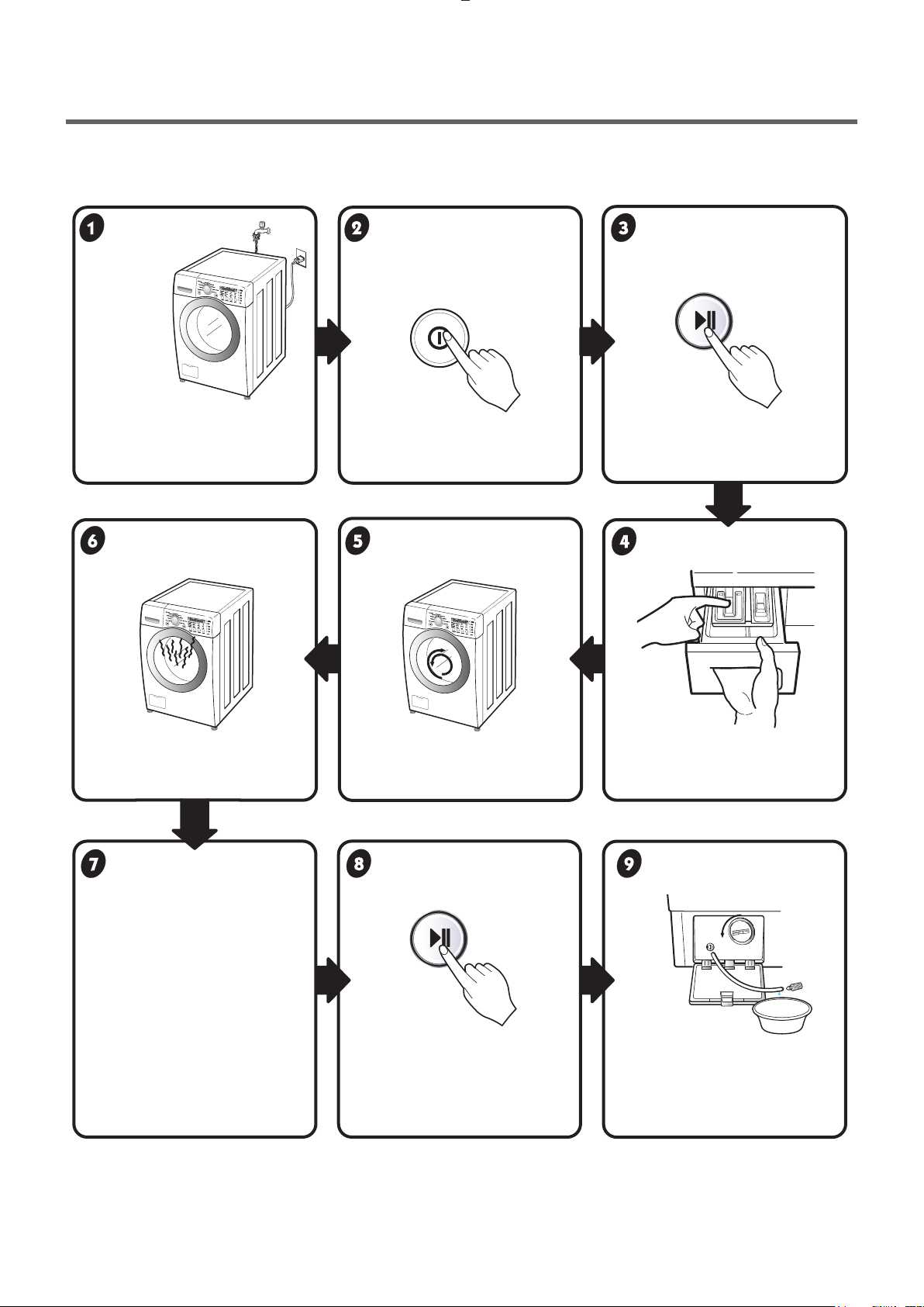
2-9. Cycle counter
Select this function to check the number of cycles.
1. Press Power button.
2. Select a cycle.
3. Press Start/Pause button.
4. Press Wash and Rinse button simultaneously, then the
number of cycles will be displayed.
If less than 1000 cycle, the number of cycles is expressed
as is.
If more than 1000 cycle, the number of thousands place
and the remaining numbers appears taking turns.
E.g. in case of 1,020
1 20 blank (repeated)
The number of cycles can be reset when Main PCB is replaced.
(It does not change in case of a simple change in the program.)

7
3. PARTS IDENTIFICATION
•If the supply cord is damaged,
it must be replaced by the
manufacturer or its authorized
service technician in order to
avoid a hazard.
Shipping Bolts
Drain Hose
Dispenser
Door
Lower Cover Cap
Drain Plug
Adjustable Feet
Drain Pump Filter
Power Plug
Cold
Water Hose
Wrench
(for removing
shipping bolts and
adjusting leveling feet)
Elbow Bracket
(for securing
drain hose)
Capuchons pour
couvrir les trous
des boulons de
transport
Control Panel
Water Circulation & Steam Nozzle
Drum Light
Drum
Door Seal
Air Vent for Safety
Cold Water Inlet
Back of Washer
Included Accessorios

8
4. INSTALLATION & TEST
1Before servicing, ask the customer what the trouble is.
2Check the setup (power supply is 220-240V AC, remove the transit bolts....).
3Check with the troubleshooting guide.
4Plan your service method by referring to the disassembly instructions.
5Service the unit.
6After servicing, operate the appliance to see whether it functions correctly.
• Remove the 4 shipping bolts
with the supplied wrench.
※Do first lower side to remove easily.
•Keep the shipping bolts and
spanner for future use.
•Insert the 4 caps
(provided) into the hole.
•
Turn clockwise to raise;
counterclockwise to lower.
• Turn the leveling feet to adjust
the appliance.
STANDARD INSTALLATION
The appliance should be installed as follows:
REMOVE THE SHIPPING
BOLTS
INSTALL THE APPLIANCE
ON A FLAT AND FIRM SURFACE
ADJUST THE
LEVELING
Lower
Keeping
Higher

9
HOW TO CONNECT THE INLET HOSE
¥ Verify that the rubber washer is inside of the
valve connector.
¥ Tighten the inlet hose securely to prevent leaks.
※The end of the drain hose should be placed less than 100 cm from the floor.
CONNECT THE DRAIN HOSE
CONNECT POWER PLUG
• Make sure that the hose is not twisted.
• Connect the power plug to the wall outlet.
•Avoid connecting several electric devices, as
doing so may cause a fire.
• Avoid submerging the end of the hose.
Cold

10
Preparation for
washing.
Press the POWER button. Press the Start/Pause
button.
•Connect the power plug to
the outlet.
•Connect the inlet hose.
•Press the WASH/RINSE button
and the present temperature will
be displayed.
•Check if the drum rotates
clockwise and counterclockwise.
Check the water heating
function.
Check the automatic
reverse rotation.
•Check if water is supplied
through the detergent dispenser.
Check the water supply.
•If SERVICE is needed during
check, remove the remaining
water by pulling out the hose cap.
Water removal.
•Listen for a click to determine
if the door is unlocking.
Press the
START/PAUSE button.
•Power off and the power on.
•Press the SPIN SPEED button
•Press the START/PAUSE button.
•Check the spin and drain
functions.
Check the drain and spin
functions.
•Listen for a click to determine if
the door has locked.
7TEST OPERATION

11
6. WIRING DIAGRAM

12
5. OPERATION
POWER BUTTON
• Use this button to turn the power
On/Off.
START/PAUSE
•Use this button to Start/
Stop the washer.
Cycle Selector Knob
•Rotate the Cycle selector knob to select the cycle designed
for different types of fabric and soil levels.
Status Indicator
•It shows elapsed time of the cycle the washer
is operating.

13
WASH, RINSE, TEMP., SPIN
•Use it to select the desired washing.
•Use it to change the number of Rinsings.
•Selects the wash temperature combination for the selected cycle.
•The washer drum spins at up to 1,200 RPM. This reduces drying time and saves energy.
Option Button
- Time Delay : You can set a time delay so that the washing machine will start automatically and finish after a specified time
interval.
- Favorite : Favorite program allows you to store a customized wash cycle for future use.
- Tub clean : This option can remove a buildup of detergent residue can occur in the wash tub over time and can lead
to a mildewy or or musty smell.
- Rinse + Spin : This can be helpful in preventing fresh stains from setting in fabrics.
- Crease Care : If you want to prevent creasing, select Crease Care option
- Beeper : Adjusts the volume of the den-of cycle beeper, or tums it off

14
Be careful of electric shock or disconnecting the parts while trouble shooting.
The voltage of each terminal is 220-240V AC and DC when the unit is plugged in.
7. TROUBLE SHOOTING
7-1.BEFORE SVC SERVICE
7-2. QC TEST MODE.
1. Press the RINSE and SPIN buttons simultaneously.
2. Press the Power button, while the above condition. Then buzzer will sound twice.
3. Press the Start/Pause button repeatedly to cycle through the test modes.
The washer must be empty and the controls must be in the off state.
The digits indicate the water level frequency ( x.1 kHz ).
So, for example a display indicating 241: a Water level frequency of 241 x.1 kHz
= 24.1 kHz
None
1 time
2 times
3 times
4 times
5 times
6 times
7 times
8 times
9 times
10 times
11 times
12 times
13 times
14 times
Turns on all lamps and locks the door.
Tumble clockwise
Low speed Spin.
High speed Spin.
Inlet valve for prewash turns on.
Inlet valve for main wash turns on.
Inlet valve for hot water turns on.
Inlet valve for steam turns on.
Tumble counterclockwise
Heater turns on for 3 sec.
Circulation pump turns on.
Drain pump turns on.
Water level inside the steam generator
Heater turns on for 2 sec
Power off and unlock the door.
rpm (40~50)
rpm
rpm
Water level frequency (25~65)
rpm (40~50)
Water temperature
Water level frequency (25~65)
Water level frequency(0~255)
Temperature inside the steam generator
Turn off all lamps.
Number of times the
Start/Pause button is pressed Check Point Display Status
*Press the Spin and Rinse button simultaneously.
7-3.HOW TO CHECK THE WATER LEVEL FREQUENCY

15
If you press the START/PAUSE button when an error is displayed, any error except 『 』 will
disappear and the machine will go into the pause status.
In case of
『 』, 『 』, 『 』,
if the error is not resolved within 20 sec., or the in case of other errors
,
if the error is not resolved within 4 min., power will be turned off automatically and the error code will
blink. But in the case of 『 』, power will not be turned off.
7-5.ERROR DISPLAY.
ERROR SYMPTOM CAUSE
WATER INLET
ERROR
• Correct water level (246) is not reached within 8 minutes
after water is supplied or it does not reach the preset water
level within 25 minutes.
1
DOOR OPEN
ERROR
•
Door not all the way closed.
•
Loose electrical connections at Door switch and
PWB Assembly.
•
The DOOR SWITCH ASSEMBLY is out of order.
2IMBALANCE
ERROR
•
The load is too small.
•
The appliance is tilted.
•
Laundry is gathered to one side.
•
Non distributable things are put into the drum.
3DRAIN
ERROR
•
Water is over flowing(over 8 level).
※If is displayed, drain pump operates to
drain water automatically.
4OVER FLOW
ERROR
•
The sensor pressure switch is out of order.
5
PRESSURE
SENSOR
ERROR
•
IThe SENSOR SWITCH ASSEMBLY is out of order.
6
HEATING
ERROR
•
The THERMISTOR is out order.
7

16
ERROR SYMPTOM CAUSE
OVER
CURRENT
ERROR
•
MAIN PWB ASSEMBLY is out of order.
•
Winding in the STATOR ASSEMBLY is short-circuited.
•
EEPROM is out of order.
※Displayed only when the START/PAUSE button is first
pressed in the QC Test Mode.
•
The washer experienced a power failure.
8
•
The connector (3-pin, male, white) in the MOTOR
HARNESS is not connected to the connector
(3-pin, female, white) of STATOR ASSEMBLY.
•
The MOTOR HARNESS between the STATOR
ASSEMBLY and MAIN PWB ASSEMBLY is cut (open
circuited).
9
10
11
LOCKED
MOTOR
ERROR
EEPROM
ERROR
POWER
ERROR
16
16
16
16
16

17
8. ERROR DIAGNOSIS AND CHECK LIST
8-1.DIAGNOSIS AND SOLUTION FOR ABNORMAL OPERATION
NO POWER
Water inlet trouble
GUIDE FOR SERVICE CALL
Is displayed?
Is the power plug connected firmly to
220-240V AC outlet?
Power failure? or Breaker opened?
Is the outlet controlled by a switch?
Visit to service.
Is the tap opened?
Is the tap frozen?
Is the water supply shut-off?
Is filter in the inlet valve clogged with
foreign material?
Visit to service.
Clean the filter of
inlet valve
SYMPTOM

18
Door error
Drain trouble
GUIDE FOR SERVICE CALL
Is displayed?
Visit to service.
Clean
up the
filter.
Close the door.
SYMPTOM
Started with door opened?
Was the load too large?
Avoid overloading.
Clicking sound is heard once or twice,
when the START/PAUSE button is
pressed to start the cycle?
Visit to service.
Check if the door switch is OK.
Is the drain pump filter clogged with foreign
material such as pins, coins, etc?
Is the drain hose frozen
kinked, or crushed?

19
GUIDE FOR SERVICE CALL
SYMPTOM
Is a low-sudsing detergent used?
Is the proper amount of detergent used
as recommended?
Recommend to reduce the amount
of detergent.
•This appliance has an automatic suds sensing function which
prevents overflow.
•When excessive suds are sensed, the suds removing
implementations such as drain, water input, pause will operate,
without rotating the drum.
Suds overflow from the
appliance.
(In this condition, wash and
spin do not operate normally)
Liquid laundry products do not
flow in.
Is the cap clogged?
Explain proper use of liquid laundry products.
Clean the compartment.
Is liquid laundry product put in the correct
compartment of the dispenser?
Visit to service.

NO POWER
20
8-2.FAULT DIAGNOSIS AND TROUBLE SHOOTING
1. Be careful of electric shock if disconnecting parts while troubleshooting.
2. First of all, check the connection of each electrical terminal with the wiring diagram.
3. If you replace the MAIN PWB ASSEMBLY, reinsert the connectors correctly.
CAUTION
(1)
(2)
(2)
Is the supplied voltage 220-240V AC?
Is the voltage between the 2 FILTER ASSEMBLY
connectors 220-240V AC?
Is the LED (1) on?
Are the connectors (2) on the PWB loose?
Is wire of the DISPLAY PWB ASSEMBLY
broken?
Replace DISPLAY PWB ASSEMBLY
or repair wire.
Check the fuse or reset
the circuit breaker.
Replace the FILTER
ASSEMBLY (CIRC).
Replace MAIN PWB
ASSEMBLY.
Reconnect.
Replace the MAIN PWB
ASSEMBLY.
This manual suits for next models
1
Table of contents
Other LG Washer manuals