LG LRV650TT User manual

CAUTION
BEFORE SERVICING THE UNIT, READ THE "SAFETY
PRECAUTIONS" IN THIS MANUAL.
WINE CELLAR
SERVICE MANUAL
LRV410TT LRV650TT LRV810TT

1. Product Specification.................................................................................................................................... 3
2. Component Names and Motions.................................................................................................................. 4
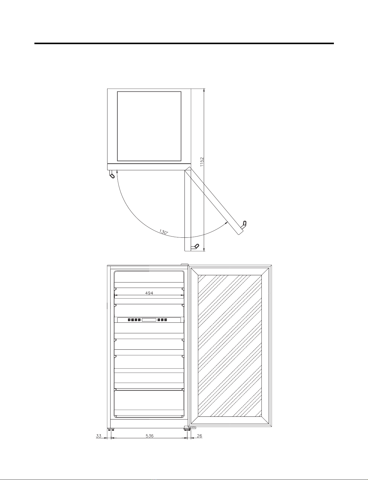
3. Exterior .......................................................................................................................................................... 7
4. Circuit Diagram ......................................................................................................................................... 12
5. Micom Function and Circuit Diagram ..................................................................................................... 14
6. Special Features ....................................................................................................................................... 30
7. Standard Self-Diagnostic Function............................................................................................................ 31
8. Maintenance ................................................................................................................................................. 32
9. Handle Disassembling, Assembling Instruction ...................................................................................... 35
10. Service Parts Chart ................................................................................................................................... 36
1. Unplug the power before you handle any electrical component.
2. If you must test the product with the power on, please wear a rubber globe in order to prevent an electric shock.
3. Check the rated current, voltage, and capacity if you are using a gauge.
4. Take caution not to let any water near the electrical component around the compressor.
5. Please use a designated part for marked parts or the circuit diagram.
6. Please remove any object from the top prior to tilting the product.
7. In order to prevent a cut from a fin, put on a glove before you repair the refrigerator or get near the heat resistor area.
SAFETY INSTRUCTIONS
TABLE OF CONTENTS
- 2 -

1. Product Specification
1-1. Rated, product specifications
1-2. Component Details
•
Interior Heater: Heat up the interior when surrounding temperature is lower than the set temperature.
- 3 -
PRODUCT SPECIFICATION
Model Name LRV410TT LRV650TT LRV810TT
Regular Contents 4.7cu.ft 7.5cu.ft 9.9cu.ft
Exterior measurements
(Width X Depth X Height) 595 X 580 X 820 595 X 580 X 1185 595 X 580 X 1475
Rated Voltage/Frequency 115V / 60Hz
Power Consumption 72W 80W 85W
Weight 47kg 64kg 71kg
Cooling Method Cool Air Automatic Circulation Type
Temperature Control Device MICOM
Outer Case Material Vinyl Coated Metal
Inner Case Material A.B.S Resin
OUT DOOR Indium Thin Oxide Triple Layers Glasses/Aluminium Deco
Insulation Material Poly Urethane Foam (Insulation Foam Gas: Cyclopentane)
693 X 717 X 946 693 X 717 X 1296 693 X 717 X 1586
51kg 74kg 81kg
Package Exterior
Measurement
(Width X Depth X Height)
Package Weight
Package
Details
Model Name LRV410TT LRV650TT LRV810TT
Compressor NR45LADG MA53LCDG
Overload Protect 4TM232NFB
P.T.C P220MC P330MC
Heater UPPER: 8W (1EA) UPPER: 8W (2EA)
UPPER: 4W (2EA) UPPER: 5W (2EA)
Interior Light 12V / 3W / 0.25A
Power Cord (Length) 1.9
Temperature Sensor Heat Reducing Load Resistance Device

2. Component Names and Motions
2-1. Interior
• Interior Light (Interior Ceiling, CASE DISPLAY & BARRIER installed in the lower column) Interior light operates by the
control panel regardless of door opening or closing.
• Interior light uses DC voltage. Please see 1-2, component details.
• 2 or 3 interior lights are installed according to model sizes and light turns on and off by control panel operation button.
2-2. Wine Rack
• Wine rack detail may vary according to the model types.
• Each rack can hold 8 wine bottles and top rack holds 9 bottles.
2-3 Others
• Glass Holder
-Hangs wine glasses. (LRV810TT)
• Wine Rack
-Stores leftover wine (tilted). (LRV810TT, LRV650TT)
• Locking Device
-Key is enclosed in the inside of the refrigerator.
• Leg Adjustor (Front & Back, Left & Right, one each)
-Please level the product using the leg adjustor.
COMPONENT NAMES AND MOTIONS
- 4 -
Model Name LRV410TT LRV650TT LRV810TT
Standard Capacity 41bottles 65bottles 81bottles

LRV810TT
COMPONENT NAMES AND MOTIONS
- 5 -
*Glass tray
Operation panel
Wine shelf
Adjustable support
Can be adjusted when
the fridge is not stable.
Light bulb
•Light bulb inside the wine
fridge can be turned on or
off by pressing the button
on the operation panel.
•Light bulb inside the wine
fridge will automatically
turn off after the door is
open for an hour.
Upper and lower
separation boards
•The upper board is ‘TOP’
and the lower one is
‘BOTTOM’. They can be
used to regulate
temperature.

LRV650TT
LRV410TT
COMPONENT NAMES AND MOTIONS
- 6 -
Operation panel
Wine shelf
Adjustable support
Can be adjusted when
the fridge is not stable.
Light bulb
•Light bulb inside the wine
fridge can be turned on or
off by pressing the button
on the operation panel.
•Light bulb inside the wine
fridge will automatically
turn off after the door is
open for an hour.
Upper and lower
separation boards
•The upper board is ‘TOP’
and the lower one is
‘BOTTOM’. They can be
used to regulate
temperature.
Operation panel
Wine shelf
Adjustable support
Can be adjusted when
the fridge is not stable.
Light bulb
•Light bulb inside the wine
fridge can be turned on or
off by pressing the button
on the operation panel.
•Light bulb inside the wine
fridge will automatically
turn off after the door is
open for an hour.

- 7 -
3. Exterior
3-1. Exterior
LRV410TT
EXTERIOR

LRV650TT
EXTERIOR
- 8 -

EXTERIOR
- 9 -

LRV810TT
EXTERIOR
- 10 -

EXTERIOR
- 11 -

- 12 -
4. Circuit Diagram
4-1. Circuit Diagram
: Indicated component is a safety part. (In case of a replacement, please use a designated part for its function and your
safety.)
LRV410TT
CIRCUIT DIAGRAM
This product is powered by electricity. Once the unit is unplugged,
please wait at least 5 minutes before you plug it back in. If you plug the
power right back in, it will cause a malfunction in the cooling machine.
MODEL: LRV410TT
Power Plug
Compressor
Exterior Temperature Sensor
Interior Temperature Sensor (Top)
Cooling Sensor (Top)
Heater (Top)
Heater (Bottom)
Case Display
Interior Light
Control Panel
BK : BLACK BL :BLUE BO : BROWN OAK BN :BROWN
YL :YELLOW PR :PURPLE GY :GRAY WH : WHITE
Temperature Indicator,
Control Panel
Interior Light

CIRCUIT DIAGRAM
- 13 -
LRV650TT/LRV810TT

- 14 -
5. MICOM Function and Circuit diagram
5-1. Functions
5-1-1. Displays
1. At the first power-up, the machine is unlocked. And, the initial setting is 57°F/RED for top, 46 F/WHITE for bottom.
5-1-2. Lock/Unlock Function
1. By pressing the ‘Lock/Unlock’button for 3 seconds, it will unlock the machine. If the control panel is idle for 10 second, it
will automatically lock itself.
2. 1 minute after the lock, the luminescence of the display will decrease.
3. You have to cancel the lock in order to operate the machine.
5-1-3. Setting the top/bottom parts’ storage temperature
(1) Top temperature setting
1. With the lock off, set the top storage temperature using ‘▽’, ‘△’button on the left side of the display.
2. By pressing ‘△’
It will display in the order of
3. By pressing ‘▽’
It will display in the order of
4. NOTE: Top temperature cannot be lower than the bottom
(2) Bottom temperature setting
1. With the lock off, set the top storage temperature using ‘▽’, ‘△’button on the right side of the display.
2. By pressing ‘△’
It will display in the order of
3. By pressing ‘▽’
It will display in the order of
4. NOTE: Bottom temperature cannot be higher than the top.
MICOM FUNCTION AND CIRCUIT DIAGRAM
WHITE LED ON RED LED ON
43°F52°F54°F64°F
64°F54°F52°F43°F
RED LED ON WHITE LED ON
WHITE LED ON RED LED ON
43°F52°F54°F64°F
64°F54°F52°F43°F
RED LED ON WHITE LED ON

5-1-4. DISPLAY OFF Function
1. With the lock off, by pressing the ‘Power’button for 3 seconds, every LED turns OFF and the machine switches to
suspension mode.
2. In the suspension mode, by pressing ‘Power’button for 3 seconds, the suspension mode is cancelled and the
Top/Bottom part displays its prior values.
NOTE: The lock is off. You can change the Top/Bottom temperature.
5-1-5. Lamp ON/OFF Function
1. Each press of the LAMP button turns on/off the LAMP.
2. If the LAMP remains turned on for over an hour, the LAMP automatically turns itself off.
5-1-6. Temperature Control
(1) Top Temperature
1. Top temperature is controlled by controlling the coolant intake valve according to the set temperature.
2. If the exterior temperature is lower than the top setting, the control increases the temperature by turning on/off the top
heater.
(2) Bottom Temperature
1. Bottom temperature is controlled by controlling the coolant intake valve according to the set temperature.
2. If the exterior temperature is lower than the bottom setting, the control increases the temperature by turning on/off the
bottom heater.
(3) 3-WAY Valve Operation Condition
1. Appropriate valve opens/closes according to each sensor temperature.
2. If both top and bottom temperature is insufficient, the part that is already in cooling process finishes its cooling, then the
other part’s valve becomes opens. (No simultaneous cooling)
3. If the cooling is not finished in given time (45min for top/30min for bottom), the parts valve in cooling process will be
closed and the other part’s valve will be opened.
*1): The opposite valve of the last satisfied part will be opened.
(4) COMP Operation Condition
1. COMP will be turned on if either the top or bottom part temperature is unsatisfied.
NOTE: If EVA sensor reading is below the set temperature, COMP will not operate.
2. If both top and bottom are satisfied, COMP switches to OFF.
3. If bottom is satisfied and top is unsatisfied after a heating, COMP will not be turned on until 30 minutes after the heating
termination.
4. If top is satisfied and bottom is unsatisfied after a heating, COMP will not be turned on until 30 minutes after the heating
termination.
MICOM FUNCTION AND CIRCUIT DIAGRAM
- 15 -
Top Part Bottom Part Valve Operation
Satisfied Satisfied 1)*
Satisfied Unsatisfied Top CLOSE / Bottom OPEN
Unsatisfied Satisfied Top CLOSE / Bottom OPEN
Unsatisfied Unsatisfied Top 45min / Bottom 30min

5-1-7. Exterior Temperature Counter Operation
1. A sensor senses exterior temperature and keeps interior temperature constant
5-1-8. Electronic Parts Consecutive Operation
Electronic parts, such as COMP, top/bottom, will operate in consecutive order to prevent a noise and parts damages from
multiple parts operating at an initial power-on and a series of test runs. (Includes temporary power outrage)
MICOM FUNCTION AND CIRCUIT DIAGRAM
- 16 -
Wine Cellar
Storage
Temperature
Spring Summer Fall Winter
Seasons
Exterior Temperature
Counter Operation
Normal Operation
Function Load Operation Order
At an initial
Power-on
Recovering from
the TEST MODE
Instantly 0.5seconds 3seconds3seconds
3seconds
3seconds
3minutes
7minutes
3minutes
10seconds
Top
Heater
OFF
Bottom
Heater
ON
Bottom
Heater
OFF
COMP
ON
POWER
ON
Top
Heater
ON
VALVE
Opening
Top
VALVE
OPEN
All
loads
OFF
VALVE
Opening
Left
VALVE
OPEN
COMP
ON

5-1-9. Malfunction Diagnosis Function
1. This function is to facilitate SVC at a time of a problem during an operation.
2. Even when a problem occurs, display buttons and LED will operate in normal condition. You can identify the problem by
pressing both ‘△’and ‘▽’button. The display will indicate the problem for 5 seconds.
NOTE: In case of a communication error, the problem will automatically be displayed on the bottom temperature
setting LED.
3. For every sensor malfunction (top, top EVA, bottom, bottom EV, Exterior sensor), all of the appropriate malfunction
indications will be displayed even when more than 2 sensors are malfunctioning.
4. In case of a communication error, the communication error has the priority. Sensor malfunction indication will not be
displayed during a communication error display.
5. Sensor malfunctions and communication error indications
5-1-10. TEST Function
1. Test function allows PCB and product function check, and malfunctioning part identification.
2. TEST S/W is on the MAIN PCB. Test mode resumes normal operation after 2 hours.
3. After you terminate the test mode, you have to cycle the power in order to resume the normal mode.
MICOM FUNCTION AND CIRCUIT DIAGRAM
- 17 -
1
2
3
4
5
6
NO Malfunctions Conditions
Indications
A part B part C part D part E part
Top sensor malfunction
Top EVA sensor malfunction
Bottom sensor malfunction
Bottom EVA sensor malfunction
Exterior sensor malfunction
Communication
malfunction
8
E
8
8
8
OFF
E
8
8
8
8
OFF
8
8
8
E
8
C
8
8
E
8
8
O
ON
ON
ON
ON
OFF
OFF
Cut wire or short circuit in top sensor
Cut wire or short circuit in top EVA sensor
Cut wire or short circuit in a bottom sensor
Cut wire or short circuit in a bottom EVA sensor
Cut wire or short circuit in an exterior sensor
No communication in 30 consecutive seconds (connector
unplugged, defected TR in communication part)
COMP VALVE DISPLAY LEDMODE Operation
TEST1
TEST2
TEST3
Resume
Normal
Operation
ON
ON
ON
P1
P2
P3
Checking for top part’s cooling system
Checking for bottom part’s cooling
system
Checking for top/bottom part’s cooling
system
Top valve OPEN
Bottom valve OPEN
TOP 45min / Bottom
15min switchover
Press TEST S/W once
Press TEST S/W once
from TEST1
Press TEST S/W once
from TEST2
Each test mode resumes the initial state after two hours
When resuming from the test mode, operation will activate after 5 minutes COMP delay

5-2. Circuit Diagram
5-2-1. Power Supply Diagram
Power supply diagram consists of a noise reduction part and a SIMPS(Switching Mode Power Supply), a rectifying part (BD1, CE1)
(from AC to DC), a switching part (IC3) for switching the DC voltage, TRANS for delivering the energy from Switch 1 to #2, Switch #2
for supplying power to MICOM and IC, and a FEED BACK(IC4) for sending a feedback to TRANS in order to maintain a consistent
voltage at #2.
There may be high voltage electricity (DC310V) on the power supply. Please wait more than 3 minutes after you unplug
the power in order to prevent an electric shock.
5-2-2. Oscillation Circuit
Synchronizing CLOCK generation for transmitting and receiving information of IC1 (MICOM) inner logic devices, and time generation
for time calculation. If specifications of OSC1 are modified, it may alter its calculation time or may cause a malfunction. Please use
regular parts.
5-2-3. RESET Circuit
When MICOM is powering up from an initial power-on or from a power outage recovery, the reset circuit initialize several parts inside
of the MICOM (C1), including the RAM. In the early stage of the power-up process, the MICOM RESET terminal is supplied with a
‘LOW’voltage for a certain period of time (10mins). (normal voltage for RESET terminal is 5.3V)
(MICOM does not operate with a defective RESET IC)
MICOM FUNCTION AND CIRCUIT DIAGRAM
- 18 -
28
(VAREF)
(VASS)
14
3
2
1
R31
R1
CC104
CC13
IC3
13
2
KIA7042AP 27
Caution

5-2-4. Load Drive Circuit
5-2-5. STEPPING MOTOR Operation Circuit (3-WAY VALVE)
According to a specified STEP numbers, send ‘HIGH’and ‘LOW’signals through MICOM PIN #16, 15, 18, and 17.
Revolving magnetism forms on the motor coil. Motor starts running.
MICOM FUNCTION AND CIRCUIT DIAGRAM
- 19 -
Load Type COMP Top Maturing Heater Bottom Maturing Heater
Measuring Parts
(IC2) #15 #13 #14
Condition
ON Below 1V
OFF 12V
CON6 IC6
R14 R15 R16 R17
16 R41
P40
P43
P42
15
18
17

5-2-6. Switch Input Circuit
Input Circuit is to sense a TEST-S/W signal for refrigerator inspection.
5-2-7. Temperature Sensing Circuit
This circuit consists of top/bottom sensor, top EVA/bottom EVA sensor for controlling top/bottom parts’storage/maturing
temperature, and an exterior temperature sensor. Each sensor’s SHORT and OPEN condition is as followed.
MICOM FUNCTION AND CIRCUIT DIAGRAM
- 20 -
P11 20
R18
Sensor Check Point Normal (-30 ℃℃~50 ℃℃) SHORT OPEN
Exterior Sensor POINT A Voltage
Top Sensor POINT B Voltage
Bottom Sensor POINT E Voltage 0.5 V~4.5 V 0 V 5 V
Top EVA Sensor POINT C Voltage
Bottom EVA Sensor POINT D Voltage
This manual suits for next models
2
Table of contents
Other LG Wine Cooler manuals