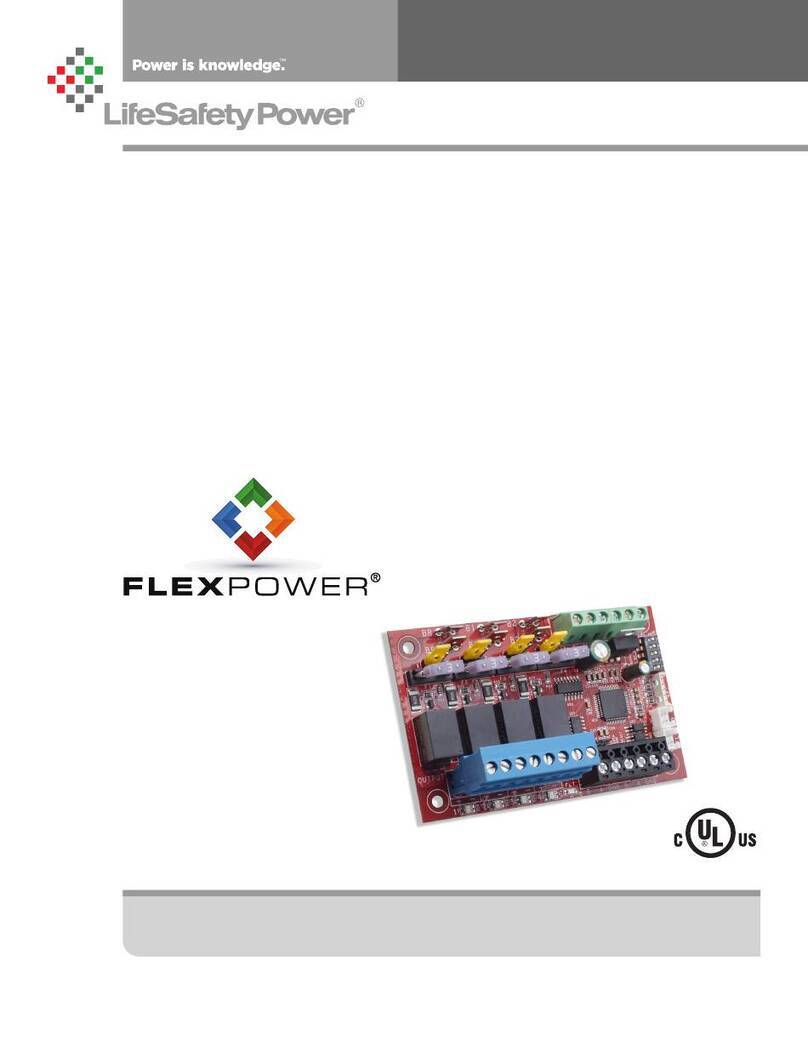
LifeSafety Power FLEXPOWER SD16 User manual

LifeSafety Power, Inc. | PH 888.577.2898 | TechSupport@LifeSafetyPower.com
P03-100 Rev A01
SD16 Installation Manual

SD16 Installation Manual
2 3
Table of Contents
Description .....................................2
Specifications ...................................2
Regulatory Information ............................2
Mounting the Managed Distribution Module............2
Managed Distribution Module Overview. ..............4
Connecting the Managed Distribution Module ..........6
Using the Managed Distribution Module...............8
Programming ..................................10
Description
The SD16 power control modules add 16 network managed
zones to an LSP power supply system for powering and mon-
itoring access control modules, readers, REX devices, or other
critical items. The SD16 MUST be used with an NL4 or NLX
network module. The SD16 accepts either one or two voltage
sources, either of which are selectable for output on a zone-
by-zone basis. Each output is selectable via software for FAI
operation.
Specifications
Power Input Voltage 12 or 24VDC nominal
Current 16A maximum
Standby Current 100ma
Zone Output Voltage Same as input
Current 1.0A resistive
Class 2 Power Limited
Event Inputs* Voltage 8-30VDC
Current 15mA Maximum
Size SD16 6.00" x 4.00" x 1.4"
(152mm x 64mm x 36 mm)
Weight SD16 0.35lb (0.16kg)
*Event Inputs not permitted to connect cables greater than 98.5 ft (30 m) long.
Regulatory Information
The equipment discussed within this manual has been tested
to the following standards:
• UL294, UL2610
• ULC S318
Mounting the Managed Distribution Module
Mounting of the board to an enclosure is via the four
snap-in standoffs supplied.
1. Locate the appropriate mounting holes in the enclosure
and snap the standoffs into the holes.
2. Align the board mounting holes with the standoffs (be
sure the PC board is properly oriented) and snap the
board onto the standoffs.
Class 2 power limited wiring must be seperated from non-power limited wiring by
a minimum of 1/4 inch and must use seperate knockouts.
The installation and all wiring methods shall be in accordance with ANSI/NFPA70
and all local codes.
For ULC compliance, installation and all wiring methods shall be in accordance
with the Canadian Electrical Code, C22.1, Part I, Section 32 .

SD16 Installation Manual
2 3
THIS PAGE BLANK

SD16 Installation Manual
4 5
BR
B2
B1
FlexIOFlexIO
+ + + +- - - -
OUT9 OUT10 OUT11 OUT12 OUT13 OUT14 OUT15 OUT16
OUT1 OUT2 OUT3 OUT4 OUT5 OUT6 OUT7 OUT8
+ + + +- - - -
+ + + +- - - - + + + +- - - -
Fault
LED
Fault
LED
OUTPUT FIELD WIRING 1-8
OUTPUT FIELD WIRING 9-16
Managed Distribution Module Overview

SD16 Installation Manual
4 5
1
Zone Outputs 1-8
These are the output terminals for outputs 1 through 8. These
terminal strips are removable and accept wire sizes from
AWG12 – AWG22. The terminals are labeled on the PC board
near the terminal strip.
2
Event Inputs
These inputs accept a voltage input to notify the system on
an event change. Commonly used to monitor the enclosure
tamper switch. Not permitted to connect cables greater than
98.5 ft (30 m) long.
3
Temperature / Humidity Sensor Input
The SD16 temperature/humidity sensor connects here. This
sensor may be used to monitor the environmental condi-
tions of the room housing the enclosure. Not evaluated by
UL.
4
Status LEDs (1 – 16) – Green/Blue and Fault (Yellow)
The Output Status LEDs indicate the status of the outputs.
LED numbers correspond with the zone number (e.g. LED 1
for Output 1).
• On SteadyOutput Powered
• SLOW Flashing (1 per second)Output Unpowered (Due
to FAI)
• FAST Flashing (4 per second) Fault Detected on Zone
• OFFOutput disabled in software
These LEDs are bi-color and indicate the output voltage for
each output as follows:
• Green – 12V Output
• Blue – 24V Output
I
NOTE LED colors are range based. Voltage Less than 13V
will show Green. Voltage above 20V will show Blue. Voltage
between 13 and 20 may show either voltage or a combination
Green & Blue. Always verify voltage with a voltmeter.
T
he yellow Fault LED lights when the SD16 detects a fault condi-
tion (including a tripped upper or lower limit - See the program-
ming section for more information). This fault condition also
transmits to the power supply through the FlexIO.
5
SPI Connector (J13)
This connector accepts the SPI cable which provides com-
munication between the SD16 and a local Netlink board.
Either this cable or an RS485 connection (#9) MUST be
connected at all times for proper operation of the SD16. The
SD16 must be connected to an NL4 or NLX board and will
not function if connected to an NL2 board.
6
FlexIO Connectors
These connectors pass the FAI and Fault signals to and
from the SD16 board and pass the FlexIO buss on to other
accessory boards in the system.
7
Buss Selection Yellow Jumpers (9-16)
The SD16 can accept up to two power inputs connected to
B1 and B2. These jumpers select which power supply input
is used for outputs 9 through 16. If a single power supply is
used, set this jumper for Position 1.
B1 This position selects the power supply connected to B1
B2 This position selects the power supply connected to B2
8Zone Outputs 9-16
These are the output terminals for outputs 9 through 16. These
terminal strips are removable and accept wire sizes from
AWG12 – AWG22. The terminals are labeled on the PC board
near the terminal strip.
9RS485 Connections
These terminals provide the RS485 connection use with an NLX network
board. See the NLX manual for connection information.
bk
BR Connectors
These fastons are for connection to the BR buss in the system.
BR acts as the Buss Return or negative connection to the
power supply.
bl
B2 Connectors
These fastons are for connection to the B2 buss in the system.
The voltage on the B2 buss comes from a second power sup-
ply or a B100 secondary supply in dual voltage systems. This
voltage will be directed to any outputs whose Buss Selection
Jumper is set in the B2 position. If the SD16 is being used in a
single voltage system, these fastons are left unused.
bm
Input Protection Fuses
These fuses protect the SD16 board in the event of a cata-
strophic failure. Replace only with the same type and rating
(ATM style, 30A).
bn
Buss Selection Yellow Jumpers (1-8)
The SD16 can accept up to two power inputs connected to
B1 and B2. These jumpers select which power supply input is
used for outputs 1 through 8. If a single power supply is used,
set this jumper for Position 1.
B1 This position selects the power supply connected to B1
B2 This position selects the power supply connected to B2
bo
B1 Connectors
These fastons are for connection to the B1 buss in the sys-
tem. The voltage on the B1 buss comes from the first power
supply. This voltage will be directed to any outputs whose
Buss Selection Jumper is set in the B1 position.
Managed Distribution Module Overview

SD16 Installation Manual
6 7
Connecting the Managed Ditsribution Module
hRemove all AC and battery power from the system before adding or replacing any accessory board.
FlexIO continues to
other accessories
FlexIO in from System
Required Connections
Optional Connections
Each of the B1, B2, BR, and FlexIO busses has two connectors.
These connectors may be used interchangeably.
For example: FlexIO from the power supply may be connected
to either of the SD16's FlexIO connectors, the Main DC voltage
source may connect to either B1 terminal, etc.
BR in from System
Input from Main DC voltage source
Input from Second DC source (optional)
BR
B2
B1 Main DC voltage continues
to other accessories
Second DC Source continues
other accessories
BR continues to
other accessories
SPI connection to
local NL4 or NLX
OUT1 OUT2 OUT3 OUT4 OUT5 OUT6 OUT7 OUT8
+ + + +- - - - + + + +- - - -
OUTPUT FIELD WIRING 1-8
FlexIOFlexIO
+ + + +- - - -
OUT9 OUT10 OUT11 OUT12 OUT13 OUT14 OUT15 OUT16
+ + + +- - - -
OUTPUT FIELD WIRING 9-16
RS485 in from NLX
RS485 continues to
other accessories

SD16 Installation Manual
6 7
THIS PAGE BLANK

SD16 Installation Manual
8 9
Using the SD16 Managed Distribution Module
This section discusses software programming of the SD16 board. It assumes a basic understanding of the NetLink soft-
ware GUI interface. Consult the NetLink manual (P03-037) for more information on using the interface.
Accessing the SD16 from the NetLink interface
From the home page of the NetLink interface, click on the
SD16 in the "Connected Devices" section near the bottom
of the screen.
The SD16 Status Page
The status page of the SD16 gives an overview of the cur-
rent state of the SD16 board and allows manual output con-
trol.
Return Button - This button returns to the NetLink Home
page. Any changes must be saved prior to clicking this
button or the changes will be lost.
Programming Button - This button opens the program-
ming page for the SD16 module
Event1/Event2 Status - These fields indicate the status
of the Event1 and Event2 inputs of the SD16.
Temperature - This field displays the temperature mea-
sured by the SD16's temperature/humidity sensor.
Humidity - This field displays the relative humidity mea-
sured by the SD16's temperature/humidity sensor.
Device ID - This field is the unique ID given to the SD16
by the NetLink.
Model - This is the model number of the board being
monitored. In this case, "SD16".
SD16 Notes - This field allows the user to enter any
notes regarding the SD16 board. Click the Save Settings
button to save the notes.
Location - This field allows the user to enter the location
of the SD16 board.
Output # - This column shows each zone number and
provides a checkbox for selecting one or more zones.
Output Description - This column shows the program-
mable descriptive name given to the zone. It can be
changed directly by clicking on the text field and typ-
ing the description for each zone. Example descriptions
include "Access Control Panel", "Front Door Reader", or
"Back Door Mag Lock". Click "Save Settings" to save the
descriptions.
Voltage (V) - This column shows the measured voltage
at the output terminals of the SD16 board for each zone.
This is only the voltage at the output of the SD16 and
does not indicate power at the field device.
Current (A) - This column shows the measured current
being drawn from the output terminals of the SD16 for
each zone.
Power (W) - This column shows the calculated power
being supplied by the output terminals of the SD16 for
each zone.
FAI State - This column shows the FAI status for each
zone. If FAI control is disabled for the zone, the field will
show "Disabled". If enabled, the field will show "Active" or
"Inactive" to show the FAI status.
Cycle Count - This coulmn shows the total number of
cycles for each output since the count was last reset.
Note that an activation must be present for at least 3
seconds to register.
Output Status -This column shows the status of each
zone of the SD16. "Normal" indicates that the zone is
working and configured correctly, and that there are no
faults on that zone. "Fault" indicates a problem with that
zone. Verify output current draw, jumper placement, and
field wiring integrity.
Enable / Disable Selected Outputs - These buttons will
manually enable or disable any outputs whose Output #
checkbox is selected.
Enable / Disable All Outputs - These buttons will manu-
ally enable or disable all outputs on the SD16.
Reset Selected / All Outputs - These buttons will manu-
ally disable outputs for 5 seconds, then return to normal.
This function is helpful for resetting devices such as
routers which would cause network loss when powered
down.
Reset Selected / All Cycle Counts - These buttons will
reset the cycle counter for one or more outputs to zero.
Save Settings - This button saves the output descrip-
tions and SD16 Notes fields when changed.

SD16 Installation Manual
8 9
The NetLink's SD16 Status Page
The SD16 Status Page

SD16 Installation Manual
10 11
From the Status page of the NetLink interface, click the "Program-
ming" button near the top left corner. This will open the SD16's
configuration page.
"Return" Button - This button returns to the SD16 Status page.
Any changes must be saved prior to clicking this button or the
changes will be lost.
"Save Settings" Button - This button will save all changes on
the page.
"Fill All" Button (top) - This button will take all settings from
Zone 1 and copy them to Zones 2 through 16.
"Export Settings" Button - This button saves the configuration
of the SD16 zones to a file, which may be imported to other
SD16 boards. If prompted after clicking, select "Save File".
Check the "Include Output Descriptions" selection to include
the output descriptions in the export file.
"Import Settings" Button - This button opens a page allowing
you to select an SD16 Configuration file to import. Click the
Browse button to select the file, then click open. After selecting
the file, click "Download" then "Confirm".
Temperature Lower limit - This field allows the user to pro-
gram a lower limit for the temperature sensor reading.
Temperature Upper limit - This field allows the user to pro-
gram an upper limit for the temperature sensor reading.
Humidity Lower limit - This field allows the user to program a
lower limit for the humidity sensor reading.
Humidity Upper limit - This field allows the user to program
an upper limit for the humidity sensor reading.
"Fill All" Buttons (Column) - Each column has a "Fill All" but-
ton. This button takes the setting from Zone 1 of that column
only and copies it to Zones 2 through 16.
Output # - This column shows each zone number
Output Description - This column shows the programmable
descriptive name given to the zone.
Disable on FAI Activation - This column has a drop-down list
to select whether an FAI condition will affect the output of each
zone. Choices are "Yes" and "No"
Email Alert on Fault - This column has a drop-down list to
select whether fault conditions on each zone will send an email
alert when email is configured in the NetLink. Choices are "Yes"
and "No".
Voltage Lower Limit (V) - This column allows setting a lower
voltage limit to trigger a fault for each zone. For example, if the
lower voltage limit is set for 23.5V, a fault will be triggered if
the voltage on that zone goes below 23.5V. This limit will not
be triggered when the zone is deactivated via the zone's input,
FAI, or other intended deactivation.
Voltage Upper Limit (V) - This column allows setting an upper
voltage limit to trigger a fault for each zone. For example, if the up-
per voltage limit is set for 26.0V, a fault will be triggered if the volt-
age on that zone goes above 26.0V.
Current Lower Limit (A) - This column allows setting a lower
current limit to trigger a fault for each zone. For example, if the
lower current limit is set for 0.25A, a fault will be triggered if
the current on that zone falls below 0.25A. This limit will not
be triggered when the zone is deactivated via the zone's input,
FAI, or other intended deactivation.
Current Upper Limit (A) - This column allows setting an upper
current limit to trigger a fault for each zone. For example, if the up-
per current limit is set for 0.75A, a fault will be triggered when the
current on that zone goes above 0.75A.
Cycle Count Limit - This column allows setting a limit to trigger
a fault when the zone is activated a certain number of total cycles.
Output Limit Setting Aid - This section allows automatic setting
of the upper and lower voltage and current limits for each output.
To utilize the automatic settings, all output field wiring must be
completed to the output devices to be powered. Enter the desired
percentage for each limit, and click the "Start Measurement" button.
The SD16 will briefly cycle each output on and off and measure the
voltage and current levels for each device. When complete, the up-
per and lower limits will be set based on the entered percentages.
Programming the SD16 Managed Distribution Module

SD16 Installation Manual
10 11
The SD16 Programming Page
The Programming Page

SD16 Installation Manual
12 PB
Section
P03-100 Rev A01 11/21 © 2021 LifeSafety Power.All rights reserved
IMPORTANT
All information, including illustrations, is believed to be reliable. Users, however, should independently evaluate the suitability of each
product for their particular application. LifeSafety Power makes no warranties as to the accuracy or completeness of the information,
and disclaims any liability regarding its use. LifeSafety Power’s only obligations are those in the LifeSafety Power Standard Terms
and Conditions of Sale for this product, and in no case will LifeSafety Power or its distributors be liable for any incidental, indirect, or
consequential damages arising from the sale, resale, use, or misuse of the product. Specifications are subject to change without notice.
In addition, LifeSafety Power reserves the right to make changes—without notification to Buyer—to processing or materials that do not
aect compliance with any applicable specification.
LifeSafety Power
10027 S 51st St, Suite 102
Phoenix, AZ 85044 USA
www.lifesafetypower.com
Phone (888) 577-2898
info1@lifesafetypower.com
Table of contents
Other LifeSafety Power Computer Hardware manuals