Lift King 165982HLK User manual

Dec. 2020
MOBILE 4-COLUMN PARKING LIFT
Model: 165982HLK
Installation & Operation Manual

165982HLK
Dec. 2020
2
Index
1. Safety Cautions………………………………………………………………………3
1.1 Important statements
1.2 Instructions for qualification of operators and users
1.3 Cautions
1.4 Safety signs
1.5 Noise standard
1.6 Training
2. Introduction to Product………………………………………………………………5
2.1 Product description
2.2 Technical parameters
2.3 Main structure part
3. Installation Instructions……………………………………………………………10
3.1 Preparation before installation
3.2 Cautions for installation
3.3 Installation procedures
3.4 Last check
4. Operation Instructions……………………………………………………………15
4.1 Cautions for operation
4.2 Operation flow chart
4.3 Operating procedures
5. Faults and Solutions………………………………………………………………17
6. Maintenance Instructions…………………………………………………………18
7. Attachments…………………………………………………………………………19
Attachment 1– Packing List of Entire Machine
Attachment 2– Overall Dimension Drawing
Attachment 3– Winding Pattern of Wire Rope
Attachment 4– Hydraulic Schematic Diagram
Attachment 5– Exploded View of Machine

165982HLK
Dec. 2020
3
Safety Cautions
1.1 Important statements
Please do note the tonnage mark on the machine. Do not try to lift any load that exceeds the rated
lifting capacity.
Please read this manual carefully before installation and use of the lift, to avoid any property loss
or personal injury caused by faulty operation.
No one is allowed to modify the control part and other mechanical parts of the machine without
the manufacturer’s permission.
1.2 Instructions for qualification of operators and users
1.2.1 Only personnel who have received professional training are allowed to operate and use
the lift.
1.2.2 Electrical connection must be performed by qualified electricians.
1.2.3 Nonprofessionals shall not approach the lifting area.
1.3 Cautions
1.3.1 Do not install the lift on asphalt or tar ground. Concrete thickness must meet requirement.
1.3.2 Please read and understand Safety Cautions carefully before operation of the lift.
1.3.3 The lift shall not be used outdoor if not being customized to special requirements.
1.3.4 Hands and feet shall be away from moving parts of the lift. Move hands and feet away
when the machine is descending, to avoid being crushed.
1.3.5 Only personnel who have received professional training are allowed to operate and use
the lift.
1.3.6 Operators are not allowed to wear fat and loose clothes, to avoid being clamped by any
moving part when the machine is descending or rising.
1.3.7 Ground around the lift must be kept clean and tidy, with no stacking of materials, in order
to avoid accident.
1.3.8 The lift is designed to lift the entire car, not part of it. Do not try to lift any car beyond the
rated lifting capacity.
1.3.9 Do make sure the safety lock of the lift is locked when personnel are working undercar.
1.3.10 Lifting block of the lift must be put at a place suggested by the car manufacturer, and then
the car shall be lifted slowly. Check the car is stable without any risk of tipping, overturn or
falling, before lifting it to the desired height.
1.3.11 Check whether any part is broken and check synchronicity of the machine and flexibility of
moving parts at any time. Perform regular maintenance. Once any anomaly is detected,
stop use immediately and contact your dealer.
1.3.12 Please lower the machine to the lowest position and turn off power after operation.
1.3.13 It is not allowed to modify any part of the lift without the manufacturer’s permission.

165982HLK
Dec. 2020
4
1.3.14 If the machine is to stand idle for a long period of time, the user shall
a. Turn off power;
b. Drain off hydraulic oil;
c. Lubricate moving parts with hydraulic oil.
Note: Do not drain liquid at random, in order to protect environment.
1.4 Safety signs
1.5 Noise standard
The lift makes noises less than75dB. For your health, it is suggested to provide a noise meter in
your operating area.
1.6 Training
Only personnel who have received professional training are allowed to operate and use the lift.
We take pleasure in helping you if the manufacturer’s professional training is needed.

165982HLK
Dec. 2020
5
Introduction of Product
2.1 Product description
This lift is a mobile parking lift. Its main parts include columns, tracks, movable brackets, hydraulic
cylinder and motor pump unit.
When the motor pump unit is powered, gear pump starts to work. Hydraulic oil pushes cylinder
rod up, pulling steel cable and hence raising tracks. During lifting, safety rack engages with safety
lock automatically to make sure that no falling is caused by possible faults of the hydraulic
system.
Safety structure chart:
Lockedstatus: Unlockedstatus:
Fig.1 Fig.2
2.2 Technical parameters
2.2.1 165982HLK
Model Rated lifting capacity Lifting time Lifting range Power supply
165982HLK 12000 LBS 50 Sec 150--2300mm 240V, 50Hz, 15Amp. single phase
Fig.3

165982HLK
Dec. 2020
6
Fig.4
Fig.5

165982HLK
Dec. 2020
7
2.3 Main structure chart
1: Control case mounting bar
3: Power unit / Motor pump
4: Main platform
5: Wheel rack
6: Offside platform
7: Column and cap
8: Cross beam
9: Approach ramp
Fig. 9

165982HLK
Dec. 2020
8
Installation Instructions
3.1 Preparation before installation
3.1.1 Installation tools and lifting equipment
Two open-end wrenches (17-19),
20 inch adjustable wrenches
One 5mm screwdriver
10L /12L, 46# anti-wear hydraulic oil
One 1t lifting equipment
One measuring tape, one chalk
3.1.2 Check against Packing List – Attachment 1 (Packing List of Entire Machine)
Unpack the package and check whether the parts are complete against Attachment 1
(Packing List of Entire Machine). Contact your dealer or the manufacturer immediately
once any omission is detected. The dealer will not take any responsibility for and solve any
problem for free, if any missing part is detected but the machine is still installed with the
missing part unresolved.
3.1.3 Requirements for ground
This lift must be installed on flat and solid concrete ground, with the concrete strength
being above 3000psi and the thickness being 200mm or greater, Within whole area the
flatness error being less than 5mm. Newly poured concrete shall be cured for more than 20
days in dry condition without direct exposure to sunshine.
3.2 Cautions for installation
3.2.1 Conduits and electric wires must be connected correctly, to avoid oil leakage and
loosening of wires.
3.2.2 All the bolts must be tightened.
3.2.3 No car shall be put on the machine during trial run.
3.3 Installation procedures
Step 1: selection of a proper installation site
This lift shall be installed indoor. It shall be installed on solid concrete ground, not on any
expansion joint of cement ground. It must not be installed on the second or higher floor, without
permission of relevant building personnel.
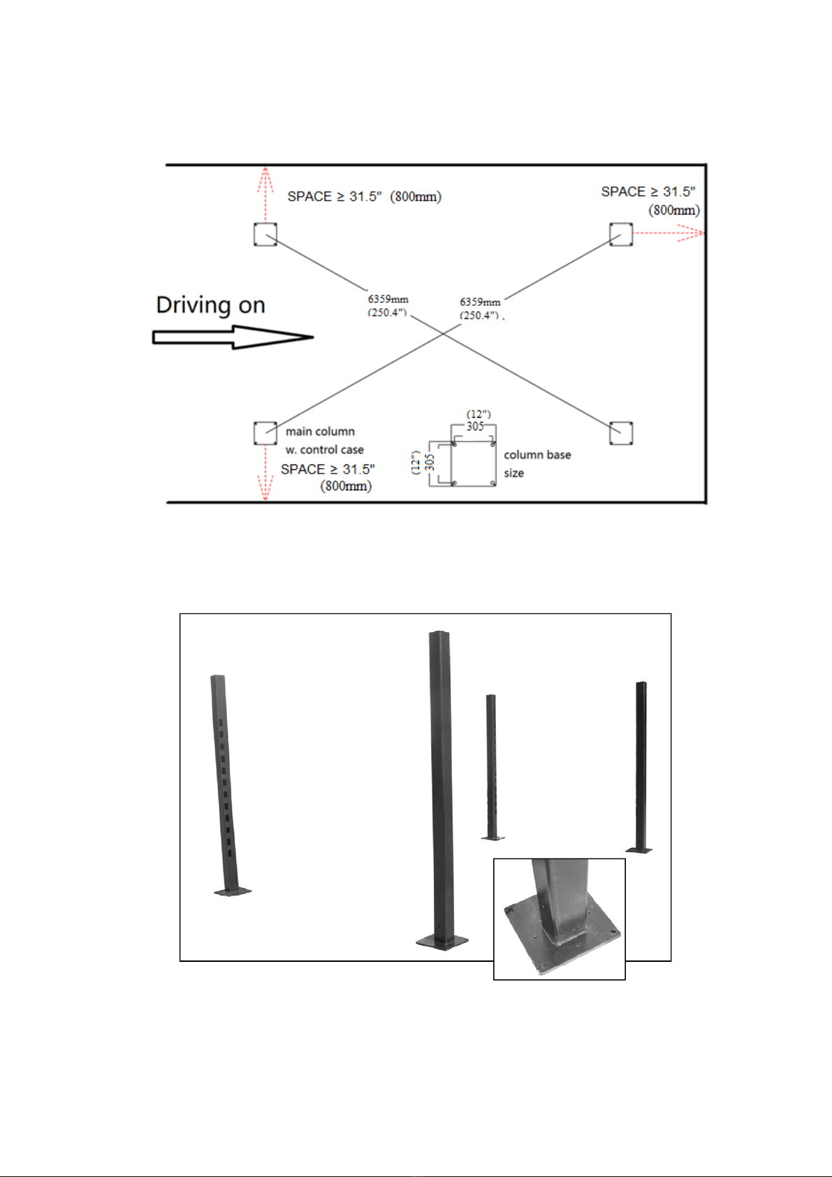
Step 2: determination of layout
When installation site is selected, mark positions of four columns with a measuring tape and a
chalk and make sure two diagonal lines equal each other. See the following drawing (Fig.10)
The space from column to wall must be kept as more than 800mm for safe walking.

165982HLK
Dec. 2020
9
Fig.10
Step 3: Unloading and unpacking
Step 4: Set up of columns (Fig. 11)
After unpacking, set up the four columns as Fig. 11
Fig. 11 (Main column with holes on base plate )

165982HLK
Dec. 2020
10
Step 5: Installation of cross beams (Fig. 12 - 24)
1. Take away the cover plate from the collar by turn off the screw.(Fig.12)
2. Using a piece of cardboard to stop the lock.(Fig. 13)
3. Install the crossbeam.(Fig.14)
4. Take away the cardboard and let the crossbeam rest on 4th position.(Fig.15)
5. Put in the nylon sliders and mount on the cover plate.(Fig. 16-17)
(The slider with cut must be at the column cutting corner as in the picture)
Fig.12 Fig.13 Fig.14
Fig.15 Fig.16 Fig.17
Step 6: Mounting on platforms (Fig. 18-19)
Put the platforms on the crossbeams. Bolt them together by bolts and nuts.
The platform with cylinder must be near the main column and the roller rails must be in the
middle.
Fig.18 Fig.19

165982HLK
Dec. 2020
11
Step 7: installation of steel cable (Fig. 20)
Fig.20 Main column
1. Put on the column top caps as Fig. 18. The one for main column is with holes (Fig.21).
2. Pull the cylinder to make sure that the cables are long enough.
3. Put on the cable-cut safe roller on the latch (Fig. 22a)
4. Get the cables out from the end of the platforms then round the
rollers and be fixed on the column top (Fig. 22b).
Fig.21 Fig.22a Fig.22b

165982HLK
Dec. 2020
12
Step 8: installation of safety lock-release device
Mount on the items on the crossbeam as Fig. 23 -- Fig. 25
Fig.23
Fig.24a Fig. 24b Fig.25
Step 9: Motor pump mounting & connecting
Fix the control case mounting bar on the main column by bolts and
screws. (Fig. 26). It can be on the side or in the front.
Then mount the motor pump on the bar by bolts and nuts also.
Fill 10L(9PRO) / 12L(9XL) HM46# anti-wear hydraulic oil into the oil
tank.
Connect the hydraulic hose from motor pump to cylinder under main
platform through a fitting. (Fig.27-28)
Fig.26(9PRO)
Fig.27(9PRO) Fig.28
Step 10:Power hooking:
Power supply : 240V, 50Hz, single phase, 15A.
Make the Electrical hookup to the motor pump (240V, Single Phase). It is recommended that a
240 Volt, 15Amp twist lock plug be installed in the power line just ahead of the power control case.
Size wire for 20 amp circuit.

165982HLK
Dec. 2020
13
Warning: the wiring must comply with local code. Have a certified electrician make the electrical
hook-up to the power control case and motor pump. Protect each circuit with time delay fuse or
circuit breaker 240V single Phrase, 60 Hz 15 Amp. Motor cannot run on 60hz without a physical
change to motor.
Step 11: steel rope tension adjusting
Note: the four locks must be at same height while doing this.
After the four safety locks totally rest on the same height, (if not, loose the steel rope nut on the
column top), turn the nut on the column top to shorten the rope on each column so that the
tension of the ropes are almost same. Please keep the lock still rest on the rack (It is about to
leave the rack but not).
Step 12: trial running (the machine must be unloaded)
Turn on the power switch on the power supply box on the wall then press the UP lifting button
until the steel ropes are tensioned. Then release the button. It is very important to check whether
all of 4 steel ropes stay within the rope groove at this moment.
Then press the UP button again until the machine rises to the highest position. It will be stopped
by the cylinder extension limit.
While rising, the locks will knock the columns making ‘Clang-Clang’ noise. It is normal that the
sound may not synchronous. It depends on the leveling of the ground and the tension on each
rope.
Press down the DOWN lever. The locks will rest on the racks of the columns and the platforms
will stop at the height.
Again press the UP button to rise the platforms a little. Then hold down the lock-release lever to
release all the locks. At the same time, press down the DOWN lever. The lift will lower down by
gravity until the DOWN button is released. In the lowering, pay attention to the locks, until the
machine descends to the lowest position.
Note: If any lock does not released before going down, the platforms will not be leveling.
Try to adjust the length of the steel cable to make all locks released before platforms
moving down.
Up and down the lift from ground to top for several times to get air out from the cylinder and hose.
3.4 Last check
a. There must be no oil leakage in the hydraulic system including motor pump, valves, hose,
cylinder and all connections.
b. Steel cable nuts must be tightened and locked on the column top.
c. All electric wiring / connection are perfect.
d. The platforms are leveling. (Note: this is depended on the floor and cable adjusting)

165982HLK
Dec. 2020
14
Turn on power switch
Lift rises
Press UP button
Motor runs
Gear pump works
Start
Turn on power switch
Press UP button 2-3 seconds
Lift descends by gravity
Lift goes up a little distance
Hold down the lock-release lever and DOWN lever
Start
Operation Instructions
4.1 Cautions for operation
4.1.1 All the conduit connections shall be checked. Operation may not be performed unless it is
confirmed that there is no oil leakage.
4.1.2 Operation is not allowed where safety device is faulty.
4.1.3 Check whether the center of gravity of the car to be lifted is at the center of the lifting
platform. If not, please adjust the center of gravity before lifting.
4.1.4 In the lifting/lowering process, operators and all the other relevant personnel shall stand
within safe areas.
4.1.5 When the platform is raised to the desired height, operators shall turn off power when
leaving the control box, to avoid faulty operation by other personnel.
4.1.6. Make sure the safety lock of the lift is locked before personnel operate under car. Make
sure nobody is under the car before lifting/lowering operation.
4.2 Operation flow chart
Lifting Lowering

165982HLK
Dec. 2020
15
4.3 Operating procedures
WARNING: Read and understand the operation instructions before operating this machine
Raising a vehicle:
1. Drive a car through the ramp on the platforms. Then stop it in the middle of the platform. Pull
parking brake (It is better put some wood to block the wheel).
2. Press the UP button to raise the car a small distance above the ground. Then check the status
of the car again.
4. Lift the car to the desired height. Press DOWN lever to rest the platforms on the safety locks.
Lowering the lift:
1. Press UP button 2-3 seconds to rise the platforms a little height.
2. Hold down the lock-release lever and the DOWN lever to lower the platforms.
2. Drive the car off after the lift descends to ground.
Moving the lift:
Note: only lift itself allow to be moved by the wheels. No load is permitted on the lift while
moving.
1. Empty the lift by driving away the vehicle.
2. Lift up the platforms to two feet high.
3. Mount on the wheel racks.(Fig. 29)
4. Lower down the platforms till the cross beams rest on the wheel racks and the column leaving
the ground.
5. Push the columns to move the lift to new position.
6. Rise up the platforms again.
7. Take away the wheel racks.
8. Lower down the platforms to ground.
Fig.29

165982HLK
Dec. 2020
16
Faults and Solutions
Note: If you could not troubleshoot any fault, please ask the manufacturer for help. We will help
you solve the problem as soon as possible. Provision of relevant information and photos of the
fault allows the manufacturer to solve the problem faster.
Fault Reason Solution
Motor does not run and
lift does not work.
Electric wire connection is poor. Check and connect wires correctly.
Motor is burned. Replace the motor.
Motor rotates but lift does
not work.
Motor reverses. Correct electric wire connection.
Overflow valve is loose or blocked. Adjust or clean overflow valve.
Gear pump needs priming or it is broken. Prime or Replace gear pump.
Hydraulic oil is insufficient. Add hydraulic oil.
Oil suction pipe is loose or drops. Tighten oil suction pipe.
Buffer valve is loose or blocked. Tighten or clean buffer valve.
Slow lowering down
occurs after lifting.
Check if there is oil leakage at any conduit. Replace conduit.
Cylinder is sealed poorly. Replace seals.
One-way valve is sealed poorly. Disassemble, clean, resolve, or replace
Overflow valve works poorly. Disassemble, clean, resolve, or replace
Manual unloading valve works poorly. Disassemble, clean, resolve, or replace
Slow lifting
Filter clogs up. Clean, resolve, or replace
Oil is mixed with air. Add hydraulic oil.
Overflow valve is not well adjusted. Adjust correctly.
Hydraulic oil turns hot (above 45°). Stop to cool down or replace hydraulic oil.
Seals of cylinder are worn out. Replace seals or cylinder.
Slow lowering
Explosion-proof throttle valve for lowering is
blocked by obstacle.
Replace, Clean, resolve or replace the
explosion-proof throttle valve.,
Hydraulic oil is not clean. Replace hydraulic oil.
There is obstacle in conduit. Clean or replace conduit.

165982HLK
Dec. 2020
17
Maintenance Instructions
Simple routine maintenance at low cost can ensure normal operation and safety of the machine. The frequency of
routine maintenance may be determined on the basis of the frequency suggested as below and according to
operating environment and times of the lift.
6.1 Items to be checked before operation every day
Operators must perform inspection before operating the machine. It is very important to check safety lock, which
must be checked every day. Inspection in advance prevents serious loss, waste of time and personal injury.
. Check the locked status of the mechanical safety lock before and during operation.
. Check connection and possible leakage of hydraulic hose and connection.
. Check electric connection.
. Check whether anchors are tight (if anchored).
. Check connection of lifting / lowering brackets.
6.2 Items to be checked weekly
. Check flexibility of moving parts.
. Check conditions of safety parts.
. Check volume of hydraulic oil by pressing the lifting button to raise the platform to the highest position. If it fails
to reach that position, hydraulic oil in the oil tank is insufficient and shall be added.
. Check whether anchors are tight (if anchored).
6.3 Items to be checked monthly
. Check whether bolts are tight.
. Check sealing of hydraulic system. If oil leakage is detected, tighten the joint.
. Check lubrication and wear of parts that need lubrication. Once any damage is detected, replace the damaged
part promptly.
6.4 Items to be checked yearly
. Drain the oil tank off to check status of hydraulic oil.
. Check lubrication and wear of parts that need lubrication. Once any damage is detected, replace the damaged
part promptly.
Note: If the machine is maintained in strict accordance with the aforesaid requirements,
the machine will be in normal working conditions all the time and most of accidents can
be avoided.

165982HLK
Dec. 2020
18
Attachments
Attachment 1 - Packing List of Entire Machine
1 Parking lift Component 1
2 Carton box of power unit Standard part 1
Attachment 2 –Winding Pattern of Wire Rope
Cylinder
rod

165982HLK
Dec. 2020
19
Attachment 3 - Hydraulic Schematic Diagram

165982HLK
Dec. 2020
20
Attachment 4 Exploded View of Machine
Parts Drawing Fig.2
Parts Drawing Fig.3
Table of contents
Other Lift King Lifting System manuals
Popular Lifting System manuals by other brands

Snorkel
Snorkel AB85J Repair parts manual

Blue Giant
Blue Giant Airbag Dock Leveler owner's manual

Sunrise Medical
Sunrise Medical Oxford/Hoyer Stature User instruction manual & warranty

Presto Lifts
Presto Lifts ECOA Series owner's manual

morse
morse 510-125 Operator's manual

Bike-Lift
Bike-Lift PSB-20 Use and maintenance manual