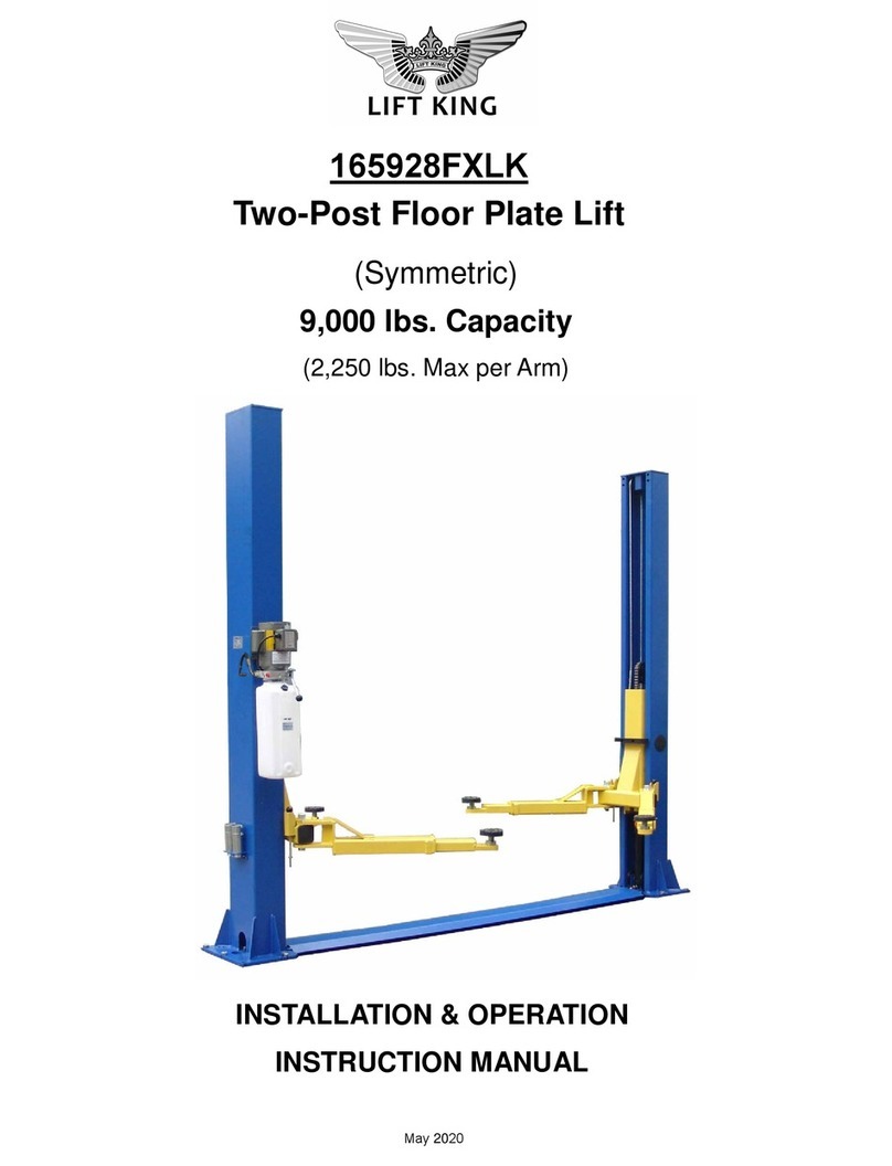
Lift King 243156LK+P04 User manual

Model243156LK+P04
Motorcycle & ATV Lift
Installation, Operation and Maintenance Manual
(Version: 2nd)
Manufactured exclusively for Lift King
May 2015

‐‐
2
CONTENT
1. Safety
1.1Note, Caution and Warning
1.2Important Information
1.3Safety Instructions
2. Technical Manual
2.1Product Description
2.2Technical Data
2.3Hydraulic Scheme
2.4 Circuit Diagram
3. Preparing and installation
3.1Site Selection
3.2Surface Condition
3.3Installation Instruction
3.4Preparation for Starting up
4. Operation
4.1Caution and Warning Label
4.2Operation Instructions
5. Maintenance Instructions
6. Parts Drawing and Parts Code List
7. Trouble Shooting Guide

‐‐
3
1. Safety Information
1.1 Note, Caution and Warning
This document uses the following conventions—Note, Caution and Warning – to alert you to
special instructions, tips, or hazards for a given procedure. Please familiarize yourself with the
conventions described below.
Indicates important information that requires special attention, such as a procedure
for a specific vehicle, or tips on operating the equipment.
Indicates the potential for damage to equipment, accessories, or the vehicle unless
you follow the instructions or procedure exactly.
Indicates the potential for property damage, personal injury, or death due to hazards
associated with the equipment, vehicle, or environment. Do no perform any
procedure until you have read and understood the warning instructions.
1.2 Important Information
1. Carefully read this manual thoroughly before installing, operating, or maintaining this lift.
2. This lift is designed for indoor use only, and should not be installed in a pit or depression.
3. The lifts have specific electrical requirements as described in the Installation Instructions
section of this manual.
4. This lift has a minimum ceiling height requirement as described in the Installation
Instructions section of this manual.
5. Failure by the owner to provide the recommended shelter, mounting surface,
electrical supply, and ceiling height could result in unsatisfactory lift performance,
property damage, or personal injury.
6. The operation of the lift is permitted by authorized person only.
7. Keep this guide as well as all the supplied technical literature in a safe place close to the
lift so that operators are able to read it whenever necessary.
8. If any confusion, please contact the service provider or your distributor.

‐‐
4
1.3 Safety Instructions
1. Do not raise a vehicle on the lift until the initialization is completed as described in this
manual.
2. Technicians should be trained to use and care for the lift by familiarizing themselves with
the publications listed above. The lift should never be operated by an untrained person.
3. Always position the pads properly out of the way before pulling the vehicle into, or out of
the bay. Failure to do so could damage the vehicle and/or the lift.
4. Do not overload the lift. The capacity of the lift is shown on cover of this document and
on the lift’s serial number tag
5. Positioning the vehicle is very important. Only trained technicians should position the
vehicle on the lift. Never allow anyone to stand in the path of the vehicle as it is being
positioned and never raise vehicle with passengers inside.
6. Position the pads to the vehicle manufacturer’s recommended pickup points. Raise the lift
until contact is made with the vehicle. Make sure that the pads and the ramps have
properly engaged the vehicle before raising the lift to a working height.
7. Keep everyone clear of the lift when the lift is moving, the locking mechanism is
disengaged, or the vehicle is in danger of falling.
8. Unauthorized personnel should never be in the shop area when the lift is in use.
9. Inspect the lift daily. The lift should never be operated if it has damaged components,
or is malfunctioning. Only qualified technicians should service the lift. Replace
damaged components with manufacturer’s parts, or equivalent.
10. Keep the area around the lift clear of obstacles.
11. Never override the self-returning lift controls.
12. Avoid excessive rocking of the vehicle when it is on the lift.
13. To reduce the risk of personal injury, keep hair, loose clothing, fingers, and all body parts
away from moving parts.
14. To reduce the risk of electric shock, do not use the lift when wet, do not expose the lift to
rain.
15. To reduce the risk of fire, do not operate equipment in the vicinity of open containers of
flammable liquids (gasoline).

‐‐
5
16. Use the lift only as described in this manual, use only manufacturer’s recommended
attachments.
17. Unusual vehicles, such as limousines, RV’s, and long wheelbase vehicles, may not
be suitable for lifting on this equipment. If necessary, consult with the manufacturer or
the manufacturer’s representative.
18. The maintenance procedures described in this manual can be done by the lift’s
owner/employer. Any other procedure should only be performed by trained lift service
personnel. These restricted procedures include, but are not limited to, the following:
cylinder replacement, platform and safety latch replacement, motor replacement,
control board replacement, oil replacement and refilling, lubrication.
19. Anyone who will be in the vicinity of the lift when it is in use should familiarize themselves
with following Caution, Warning, and Safety related decals supplied with this lift, and
replace them if they are illegible or missing.
20. Travelling on the load carry device is forbidden.
21. Never move the lift when the vehicle is loaded.
22. Only use on a level ground.
23. Wear necessary protective equipments before use.
24. Only remove the vehicle when the lift carrier locates at the lowest position.
25. Never lift the vehicle with person’s riding on it.

‐‐
6

‐‐
7
2. Technical Specification
2.1 Product Description
The 243156EHH motorcycle & ATV lift is used for repairing and maintaining motorcycles by
AC power source incorporating the latest safety technologies. Its plug connector accords with
European standard and VDE rated. Designed and manufactured for a lifting capacity of
1,000kg, is fully capable for lifting motorcycles, ATVs and safely holding them in an elevated
position.
It consists of a fixed structural scissor lift and a remote controller.
2.2 Technical Data
Capacity 1,000 kg
Lifting Height, Max 1,200 mm
Height, Min 180 mm
Width Overall 800 mm
Platform Length, Max 2,250 mm
Platform Width 800 mm
Electric Supply Tolerance ±10%,±1HZ
Power Unit 110V, 60Hz, 10A, 1.1KW
Ambient Air Temperature +5℃~ +40℃
Ambient Air Humidity 30% ~ 95%
Altitude below 1,000m above sea level
Storage Temperature -25℃~ +55℃
Noise <70db
Motorcycle Wheel Width 75~160mm
Net Weight 265Kg

‐‐
8
Fig. 1

2.3
1.
5.
9.
Hydrauli
c
Oil tank
One-way va
Relief valve
c
Scheme
2.
lve 6.
10.
Mesh
Mesh
Restrictor v
a
‐‐
9
Fig. 2
3.
G
7.
S
a
lve 11.
C
G
ear pump
S
olenoid val
v
C
ylinder
4.
M
v
e 8.
R
12.
P
M
otor
R
estrictor va
P
ipe
lve

‐‐
10
2.4 Circuit Diagram
Fig. 3
Item Name Type and Specifications Qty.
SB1 switch LA42P 220V 10A 3
SB2 switch LA42P 220V 10A
SB3 switch LA42P 220V 10A
SA switch LA42MY 220V 10A 1
KM AC contactor NC1-09/10-24VAC 400V 9A 1
FR Overload relay TA25DU 1
TR transformer ABL6TS06B 1
BR bridge rectifier KBPC1010 1A 1000V 1
FU1 Fuse ∮5×20 delay 1A 2
FU2 Fuse ∮5×20 delay 3.15A 1
FU Fuses ∮6×30 delay 10A 2
MA1 AC motor ML802-4F, 1PH/230V/50Hz,1.1KW 1
YV electromagnet TAU1564T 24VDC 520mA 2
YT Solenoid valve 24VDC 1A 1

‐‐
11
3. Preparing and installation
3.1.Site Selection
The hydraulic motorcycle lift is designed only for indoor use. Application in a room with
explosion hazard is not permitted. Setting in a wet place, a car wash center for instance, is
forbidden.
3.2. Surface Condition
The lift should be installed on level ground with a concrete surface free from as many defects
as possible to prevent unit from tipping or rocking.
Failure in accomplish the foundation requirement may cause the lift instability or
personal injury. Installing on asphalt, soft clay floor or near the expansion gap is
prohibited.
3.3.Necessary Tools
Rubber Hammer, Sockets and Open End Wrenches. Ratchet Driver, Vice Grips
3.4.Personal Protective Equipment
Always wear proper protective Equipment like working suit, shoes, gloves & glasses, etc.
3.5.Installation Instruction
1. Unpacking
Open the carton. Using a forklift to take out the bench then move to desired position (Fig. 4a,
4b) and the lift up the upper platform.
Fig.4a Fig.4b Fig.5
2. Assembling
a. Loosely attach the vice rails in the appropriate holes in the front deck of lift ( Fig.5).

‐‐
12
b. Insert wheel vice base into the rails and make certain there is clearance to allow a smooth
sliding motion ( Fig. 6).
c. Bolt the rails to the deck. Then mount on the wheel vice.(Fig. 7).
d. Insert the sideboard bar into the side holes. Bolt them with bolts. ( Fig.8,9,10)
e. Put on the side board and the rear ramps. (Fig 11)
Fig.6 Fig.7 Fig.8
Fig.9 Fig.10 Fig.11
3. Fill the tank and change the tank plug
a. Fill the tank with 6 liter of hydraulic oil AW32 OR AW46.
b. Change the tank plug( black) with a ventilating one
( brass). (Fig. 12)
4. Power Hooking
Have a certificate electrician establish a 110V/60Hz/10A power supply to the motor through the
plug. A protection against indirect contact (RCCB) shall be provided by the user.
3.6.Starting up
1. Raise the platform to full height by pressing the UP button.
2. Lower the lift to floor by press DOWN button.
3. Circle up and down for several times with stop for 2 min to
get air out from the hydraulic system.
Note: While doing, no load is on the platform. Fig.13
Now the lift is ready for operating.

‐‐
13
4. Operation
Be sure to read and familiarize yourself with the Safety Instructions at the beginning of this
manual. Be sure to wear gloves, protection glasses and all necessary personal protective
equipments. Failure to follow Safety Instructions may result in property damage, personal
injury or death.
4.1 Caution and Warning Label
4.2 Operating Instructions
Be sure to read and familiarize yourself with the Safety Instructions at the beginning
of this manual. Failure to follow Safety Instructions may result in proper damage,
personal injury or death.
To avoid personal injury and/or property damage, permit only trained personnel to
operate lift. After reviewing these instructions, get familiar with lift controls by
running the lift through a few cycles before loading vehicle on the lift.
DO NOT leave ramp attached to lift while in operation or in up position.
ALWAYS use tie downs to secure vehicle to lift while operation.
4.2.1 Lift Preparation:
Lift must be fully lowered and fields clear of all personnel before the vehicles brought on lift.
4.2.2 Loading Lift:

‐‐
14
Push the equipment over the lift while keeping the equipment parallel with the lift and aligning
the center of gravity of the equipment with the center of the lift. For motorcycles and other two
wheel vehicles/equipment, push forward until the front wheel goes into the wheel clamps.
Motorcycle Fixing. Engage the parking break of the equipment if applicable. Secure
motorcycle to lift using clamps and straps. Straps MUST be used to secure motorcycle.
Clamps are only for temporary holding.
4.2.3 Power Connection
Plug in the socket once the lift is proper located. Be sure to wear gloves before starting up.
4.2.4 Emergency button
Release the emergency button on the remote controller.
4.2.5 To Raise Lift
a. Push UP button ( ) on the controller.
b. Raise vehicle until the clear the floor, then release the UP button.
c. Check wheel clamps and secure straps.
d. Continue to raise to desired height only if vehicle is secure on lift
e. Push the PARKING button ( ) to lower the platform into the locking position
and the locking latches will be engaged.
When any emergency situation comes, press down the red emergency stop
button immediately to stop the vehicle lift. When all emergencies are solved,
turn the key clockwise to disengage the emergency stop.
Before attempting to lift pickup ATVs, be sure that vehicle is stable and proper
secured on lift
4.2.6 To Lower Lift
a. Check all danger points of the lift and be sure that there are no objects or people in
the working area (danger area) around the lift or under the lift.
b. If the platform already in lock position (latches are engaged), press UP button 2
seconds to raise up the platform a little. The latches will be released.

‐‐
15
c. Then press DOWN button ( ) on controller to lower down the lift to the required
working height or to its lowest (fully collapsed) position.
d. Observe the complete lowering process for any unexpected movement.
e. Push back the vehicle out of the lift if the lift is in the lowest position.
f. Remove any tools or stands from under vehicle before moving vehicle
Remain clear of lift when lowering vehicle. Observe pinch point warning decals.
If lift is not operating properly, DO NOT use until adjustment or repairs are
made by qualified lift service personnel.
DO NOT using the PARKING button instead of the DOWN button
NEVER press UP or DOWN button for a long time while the lift is not moving, or
the whole control system will be damaged. Relief the button if you find the lift is
not responding to the button actuated.
Once finished operation, switch off the power supply, engage the emergency
button and unplug the lift.
If any unsafe movement of the lift happens, do not to operate the lift anymore
and call the local distributor for assistance

‐‐
16
4.27 To lower the wheel clamp with wheel
a. If the motorcycle wheel need to be taken off, first loose the nuts on the wheel shaft
and rest the wheel on the clamp.
b. Loose the bolts on the platform end of the wheel board. Then move them aside with
hand hold the wheel clamp base.
c. Lower the base together with the wheel slowly. It will be easy to do service job of the
wheel.

‐‐
17
5. Maintenance Instructions
Contact your service provider for instruction before starting up if you are not completely
familiar with automotive lift maintenance procedures. Only qualified personnel can perform
maintenance on this equipment. Any failure in operation may cause personal injury or death.
9Wear necessary protective equipments before use, includes, but not limited, gloves and
protection glasses, working suits and shoes.
9Always keep bolts tight. Check periodically.
9Always keep lift components clean.
9Always if oil leakage is observed, contact your service provider.
9Check safety latches for free movement and full engagement with lift are working
9Check hoses connections for leakage.
Every Month
9Lubricate locking latch shafts. Push latch handle several times for oil to penetrate joints.
9Lubricate the sliding pieces with heavy duty bearing grease.
9With lift lowered check the hydraulic fluid level. If necessary add oil as described in the
Installation Instruction section of this manual
9Check platform latch synching: Latches should click at the same time. If necessary adjust
equalization cables as described in the Installation Instruction section of this manual.
9Check tightness of all bolts.
9Check the nuts for tightness every week for the first month, and every month afterwards.
Every 3 Months
9Check and clean the oil filter

‐‐
18
Every 6 Months
9Check the hydraulic oil if it is enough. Ensure the liquid level of the hydraulic oil that under
the max graduation and above the min graduation. The tank capacity of the power unit is
about 3L, Refill with hydraulic oil if necessary: AW 32 or 46 Non-Detergent Non-Foaming
Anti-Wear Hydraulic Oil.
9If Lift stops short of full rise or chatters, contact your service provider.
9Replace all caution, warning or safety related decals on the lift If unable to read or missing.
Reorder labels from service provider.
9Check all components wear situation.

‐‐
19
6. Parts Drawing and Parts Code List
6.1 Parts drawing-A1
2
9
4
3
11
12 13 14 15 16
17
22
23
20
24
4-1
21
25
8
26
27

‐‐
20
6.2 Parts drawing-A2
29
31
32
37
33
34
35
38
39
40
41 38
44
43
42
39
30
36
38
45
48 47
46
49
50
Table of contents
Other Lift King Lifting System manuals
Popular Lifting System manuals by other brands

Caliber
Caliber MOTO RampPro 13561 Assembly instructions

Simpro
Simpro EUROVER user manual

Graham Field
Graham Field Lumex LF1030 user manual

Performance Tool
Performance Tool W1642 owner's manual

Savaria
Savaria Stairfriend owner's manual

Walker Magnetics
Walker Magnetics BUX BM2 Owners/operators manual and safety instructions