Lift King 165948BLK User manual

Model 165948BLK
Turned Two-post Hydraulic Lift
(Clear Floor type)
Operation Manual
(2nd edition)
Manufactured exclusively for Liftking Hoists
May 2015

2
CONTENT
1. Safety Information
1.1Note, Caution and Warning
1.2Important Information
1.3Safety Instructions
2. Technical Manual
2.1Product Description
2.2Technical Data
3. Installation
3.1Site Selection
3.2Surface Condition
3.3Tools Required
3.4Installation Procedure
3.5Hydraulic Scheme
3.6Control-Box Diagram
4. Operation
4.1Caution and Warning Label
4.2Operation Instructions
4.3Maintenance Instructions
5. Parts List
6. Troubleshooting Guide

3
1. Safety Information
1.1 Note, Caution and Warning
This document uses the following conventions—Note, Caution and Warning – to alert you to
special instructions, tips, or hazards for a given procedure. Please familiarize yourself with the
conventions described below.
Indicates important information that requires special attention, such as a procedure for a
specific vehicle, or tips on operating the equipment.
Indicates the potential for damage to equipment, accessories, or the vehicle unless you
follow the instructions or procedure exactly.
Indicates the potential for property damage, personal injury, or death due to hazards
associated with the equipment, vehicle, or environment. Do no perform any procedure
until you have read and understood the warning instructions.
1.2 Important Information
1. Read this manual thoroughly before installing, operating, or maintaining this lift.
2. This lift is designed for indoor use only, and should not be installed in a pit or depression.
3. The floor on which the lift is to be installed must be 200 mm minimum thickness concrete,
with a minimum compressive strength of 3000 psi, and reinforced with steel bar.
4. The lifts have specific electrical requirements as described in the Installation Instructions
section of this manual.
5. This lift has a minimum ceiling height requirement as described in the Installation Instructions
section of this manual.
6. Failure by the owner to provide the recommended shelter, mounting surface, electrical
supply, and ceiling height could result in unsatisfactory lift performance, property damage,
or personal injury.
7. The operation of the lift is permitted by authorized person only.

4
1.3 Safety Instructions
1. Do not raise a vehicle on the lift until the installation is completed as described in this manual.
2. Technicians should be trained to use and care for the lift by familiarizing themselves with the
publications listed above. The lift should never be operated by an untrained person.
3. Always position the arms and adapters properly out of the way before pulling the vehicle into,
or out of the bay. Failure to do so could damage the vehicle and/or the lift.
4. Do not overload the lift. The capacity of the lift is shown on cover of this document and on
the lift’s serial number tag
5. Positioning the vehicle is very important. Only trained technicians should position the vehicle
on the lift. Never allow anyone to stand in the path of the vehicle as it is being positioned
and never raise vehicle with passengers inside.
6. Position the arms to the vehicle manufacturer’s recommended pickup points. Raise the lift until
contact is made with the vehicle. Make sure that the arms have properly engaged the vehicle
before raising the lift to a working height.
7. Keep everyone clear of the lift when the lift is moving, the locking mechanism is disengaged,
or the vehicle is in danger of falling.
8. Unauthorized personnel should never be in the shop area when the lift is in use.
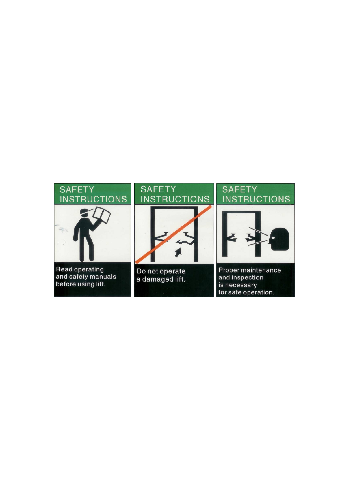
9. Inspect the lift daily. The lift should never be operated if it has damaged components, or
is malfunctioning. Only qualified technicians should service the lift. Replace damaged
components with manufacturer’s parts, or equivalent.
10. Keep the area around the lift clear of obstacles.
11. Never override the self-returning lift controls.
12. Use safety stands when removing or installing heavy vehicle components.
13. Avoid excessive rocking of the vehicle when it is on the lift.
14. To reduce the risk of personal injury, keep hair, loose clothing, fingers, and all body parts away
from moving parts.
15. To reduce the risk of electric shock, do not use the lift when wet, do not expose the lift to rain.
16. To reduce the risk of fire, do not operate equipment in the vicinity of open containers of
flammable liquids (gasoline).
17. Use the lift only as described in this manual, use only manufacturer’s recommended
attachments.

5
18. Unusual vehicles, such as limousines, RV’s, and long wheelbase vehicles, may not be
suitable for lifting on this equipment. If necessary, consult with the manufacturer or the
manufacturer’s representative.
19. The troubleshooting and maintenance procedures described in this manual can be done by
the lift’s owner/employer. Any other procedure should only be performed by trained lift service
personnel. These restricted procedures include, but are not limited to, the following:
cylinder replacement, carriage and safety latch replacement, column replacement,
overhead structure replacement.
20. Anyone who will be in the vicinity of the lift when it is in use should familiarize themselves with
following Caution, Warning, and Safety related decals supplied with this lift, and replace them
if the are illegible or missing.
Disclaimers
The information contained in this manual was considered accurate at the time of printing and is
subject to change without notification. Any corrections should be directed to KERNEL

6
2. Technical Manual
2.1 Product Description
The 165948M 2-post hydraulic lift is a surface mounted, frame contact lift incorporating the latest
safety technologies. Designed and manufactured for a lifting capacity of 4,000kg, is fully capable
for lifting vehicles, vans and trucks and safely holding them in an elevated position.
The 165948M 2-post hydraulic lift consists of a fixed structural unit (base and posts), the mobile
unit (carriage and arms), the hydraulic power system and safety devices.
2.2 Technical Data
Capacity 4,500 kg / 10000lbs
Lifting Height 1,630mm / 64 3/16”
Height Overall 3,692 mm / 145 3/8”
Width Overall 3,985 mm / 156 7/8”
Front Arm Reach, Max. 1,259mm / 49 9/16”
Front Arm Reach, Min. 635 mm / 25”
RearArm Reach, Max. 1,840 mm / 72 7/16”
RearArm Reach, Min. 860 mm / 33 7/8”
Power Unit 220V, 60Hz, single phase. (16A, 2.2KW)
Ambient Air Temperature +5℃~ +40℃
Ambient Air Humidity 30% ~ 95%
Altitude below 1,000 m above sea level
Storage Temperature -25℃~ +55℃

7
Fig. 1 – Front View Spec.

8
Fig.2 –Top View Spec.

9
3. Installation
3.1.Site Selection
The hydraulic lift is designed only for indoor use. Application in a room with explosion hazard is not
permitted. Setting in a wet place, a car wash center for instance, is forbidden.
3.2.Surface Condition
The 2-post hydraulic lift should be installed on level ground. The foundation must be 200mm
minimum thickness concrete, with a minimum compressive strength of 3,000 psi, reinforced with
steel bar.
Failure in accomplish the foundation requirement may cause the lift instability or
personal injury. Installing on asphalt, soft clay floor or near the expansion gap is
prohibited.
3.3.Tools Required
Tools requires for installation:
Concrete hammer drill.
Open end wrench
Torque wrench
Deep socket or wrench
Socket
Level (450 mm minimum length)
Vise grips
Tape measure
Funnel
Hoist or Forklift
Two 4 meter step ladders
6.35 mm drive ratchet with 8 mm socket

10
3.4.Installation Procedure
DO NOT USE THESE LINES TO POSITION THE COLUMNS, FOLLOW THE
INSTRUCTIONS IN THIS MANUAL.
1. Read this manual thoroughly before installing, operating, or maintaining this lift.
2. Site Evaluation and Lift Location:
A. Always use an architect’s plan when provided. Before unpacking the lift entirely,
determine if the site is adequate for the lift model being installed see figures 1 & 2 for
typical bay layout and ceiling height requirements.
B. Snap chalk lines to identify the lift’s centerline (Fig.3).
Fig. 3
Snap a chalk line parallel to the lift’s centerline, spaced 230 mm toward the rear of the bay.
This line represents the back edge of the column bases.
C. Snap chalk lines parallel to the lift’s centerline spaces 1,750 mm to the left and 1,750
mm to the right. These lines represent the APPROXIMATE outside edges of the column
bases.

11
3. Unpack the lift. Remove the swing arms, bolt box, power unit box, and overhead beam.
A. Save all packing hardware, as these components are necessary to complete the
installation.
B. Remove the bolts from the uprights which hold the two columns together.
C. Remove the upper column. Do not stand the columns up now but lay the columns with
their flat backs on the floor.
4. Attach the cylinder base and the cross beam base on the column using bolts, washers
and nuts provided as shown in figure 4a &4b.
Fig.4a Fig.4b Fig.5a
5. Install hydraulic cylinders.
A. Install the cylinder to the cylinder base with cylinder pin and the bolts, bushings
(spacers), washers, and nylon nuts, as in figure 5.
B. The hose connecting port near the other end of the cylinder should be positioned
pointing to the column’s opening. (Fig. 5b)
C. Bolt the cylinder rod with the carriage. (Fig. 5c)
Fig.5b Fig.5c

12
6. Set up the columns at e desired place facing each other. Then lift up the carriage to first
latch locking height (about one foot high). (Fig. 6)
Attention: (1) the main column is suggested at the left hand with
vehicle head forward.
(2) the distance between column to wall is suggested to be
at least 2 feet for safe.
Fig. 7a
Fig.7b Fig.6
7. Assemble the ceiling safety device to the overhead cross beam. (Fig. 7a, 7b & 7c) Then
Install the beam on the column tops. (Fig. 7d )
Fig.7c Fig.7d
8. Mount the cable seat with roller on the beam base at the top of the column. (Fig. 8)
Fig.8a Fig.8b

13
9. Rout the balancing cables.
Rout the balancing steel cables according to Fig. 9a, 9b, 9c, 9d & 9e from carriage to carriage
through the cable rollers.
Fig.9a Fig.9b Fig.9c
Fig. 9d & 9e cable routing

14
10. Install the fittings on cylinder(Fig. 10), and rout the hoses and pipes
A. Hose connecting
1. Connect the longest hose from the cylinder in off side column to the top of main side
column. Remember to rout the hose through the hook on cross beam. (Fig. 10a &
10b)
2. Then through a T-fitting, one middle length hose connecting to the main side cylinder.
(Fig. 10c)
3. Another shortest hose from the T-fitting goes to the motor pump. (Fig. 10d)
Fig.10d Fig.10c Fig.10a
Fig. 10b

15
Fig.11a Fig.11b
B. Return pipe connecting
1. Screw in an elbow pipe fitting on the end of the off side cylinder (Fig. 11a).
2. Screw in another T pipe fitting on the end of main side cylinder. (Fig. 11b)
3. Connect the return pipe from off side cylinder to main side cylinder through fittings.
Then it goes to the motor pump also.
11. Mount on the motor pump on main side
column (Fig. 12) with bolts and nuts
A. Connect the hose and the pipe to the pump
valve block.
DO NOT HOLD THE CYLINDER ROD IN A WAY
THAT COULD DAMAGE THE FINISH.
CYLINDER LEAKS CAUSED BY DAMAGED RODS
ARE NOT COVERD BY WARRANTY.
Fig. 12
12. Ceiling switch cable wiring and accessories
mounting.
A. The ceiling limit switch cable must be
connected in the contactor of the motor pump.
(Fig. 13) according to the wiring label.
.
Fig. 13

16
B. Install arms
1. Position the gears with TOP against the bottom of the arms in the orientation shown
in Fig.14. Attach the gears to the arms with bolts. Do not tighten at this time.
2. Position the restraint pawls on the carriage to mate with the gears on the arms.
3. Install the swing arms and pins.
Suggestion:
The longer arms go to the rear or drive in side of the lift, and the short arms go to the
front.
Don’t force the gears, it may be necessary to pull up on the restraint actuator pin in
order to install the swing arm pin.
4. Tighten the gear bolts to 40~46N-m.
Fig. 14a and 14 b
13. Column anchoring.
Note:
A. The anchor bolts must be installed at least 145 mm from any edge or seam in the
concrete.
B. The concrete must be at least 108 mm thick with a compressive strength of 3,000 psi.
C. Use a hammer drill with a Carbide tip, 19 mm diameter, solid drill bit.
↓
STEPS:
1. Using the column as a template, drill the anchor bolt holes for the Main side column
Only!!
2. Assemble the washers and nuts onto the anchor bolts. Thread the nuts onto the anchor
bolts where the tops of the nuts are just above the top of the bolts. Using a hammer,
carefully tap the anchor bolts into the concrete until the washer rests against the base
plate. Do not damage the nuts or threads.

17
3. Using a level, plumb the main side column both side to side and front to back. Shim the
column as necessary next to and on both sides of the anchor bolts, (Figure 15). If more
than 13 mm of shimming is required, do not use the anchors and shims provided with
the lift. Use longer anchors and fabricate larger shims from steel flat, 6.5 mm or 13 mm
thick by 50 mm, or more, wide.
Fig 15
4. Once the column is plumb tighten the anchor bolts to 203 N-m. Do not use an impact
wrench on anchor bolts.
a. If after tightening the anchor supplied with the lift extends more than 57 mm above
the floor the anchor does not have enough embedment.
b. If an anchor will not reach 203 N-m or does not have enough embedment or
adequate spacing cannot be achieved, replace the concrete under the column
with a 1220 X 1220 X200 mm thick pad of 3,000 psi concrete keyed under the
existing floor. Let the concrete cure before reinstalling the lift.
5. Recheck the column’s verticality after tightening the anchor bolts.Add shims if necessary.
6. Using a level check the alignment and plumbness of the entire structure. Plumb the
offside column both side to side and front to back. (the column be perpendicular to the
floor and parallel to the other column)
7. Same as main column, drill then anchor the off side column as well.
14. Fill the tank.
Remove the fill level screw of the power unit tank. Fill it with Dexron IIIATF or hydraulic oil
that meets ISO-22, until fluid reaches the bottom of the screw hole. Replace the fill screw
and tank breather.
15. Lubricate the four inside corners of both columns with heavy duty grease.

18
16. Power hook up.
Please connect the motor pump to a power supply (220V/60Hz, single phase)
WARNING:
While hooking up the power supply to the control box, please ask an expert or electrician to do
it for you. The supply circuit and the breaker must be capable for at least 50A current.
17. Testing
Note: (1) in this step A, there is no load on the lift.
(2) Circle up and down must be with interval rest of 2 min.
(3) Also refer to the operation steps in chapter 4.
A. Without a load, raise the lift empty to the top of its travel and lower it to the floor three (3)
times to remove the remaining air from the hydraulic system.
B. The latches should click together as the lift is being raised.
C. The first time a vehicle is placed on the lift, raise it no higher than three feet. Lower
the vehicle onto the safety latches. Raise the lift a few inches and pull out both latch pull
rods then lower the vehicle to the floor.
D. Raise the vehicle to full height and lower the carriages onto the safety latches. Lower the
vehicle to the floor.
E. After cycling the lift ten times with a vehicle on it, recheck the tightness of the anchors
to at least 122 N-m.
Now the lift is ready for operation.

19
3.5.Hydraulic Scheme
1. Oil Tank 2. Mesh 3. Gear Pump
4. Power Unit 5. Overflow Valve 6. One-way Valve
7. Cylinder 8. Hand Release Valve 9. Pressure Gauge (not supplied)
Hydraulic Pump 2.2KW, 2850 rpm
Setting Pressure 20 Mpa
Flow rate for the Pump 2.1 ml / rev

20
4. Operation
Be sure to read and familiarize yourself with the Safety Instructions at the beginning of this manual.
Failure to follow Safety Instructions may result in property damage, personal injury or death.
4.1 Caution and Warning Label
Table of contents
Other Lift King Lifting System manuals