CHIEF Kahuna User manual

OWNERS MANUAL
KAHUNA
2009 © Chief Automotive Technologies.
USERS MANUAL


KAHUNA
Users Manual
1
TABLE OF CONTENTS
WARRANTY.........................................................................................................2
GENERAL SAFETY INSTRUCTIONS .................................................................3
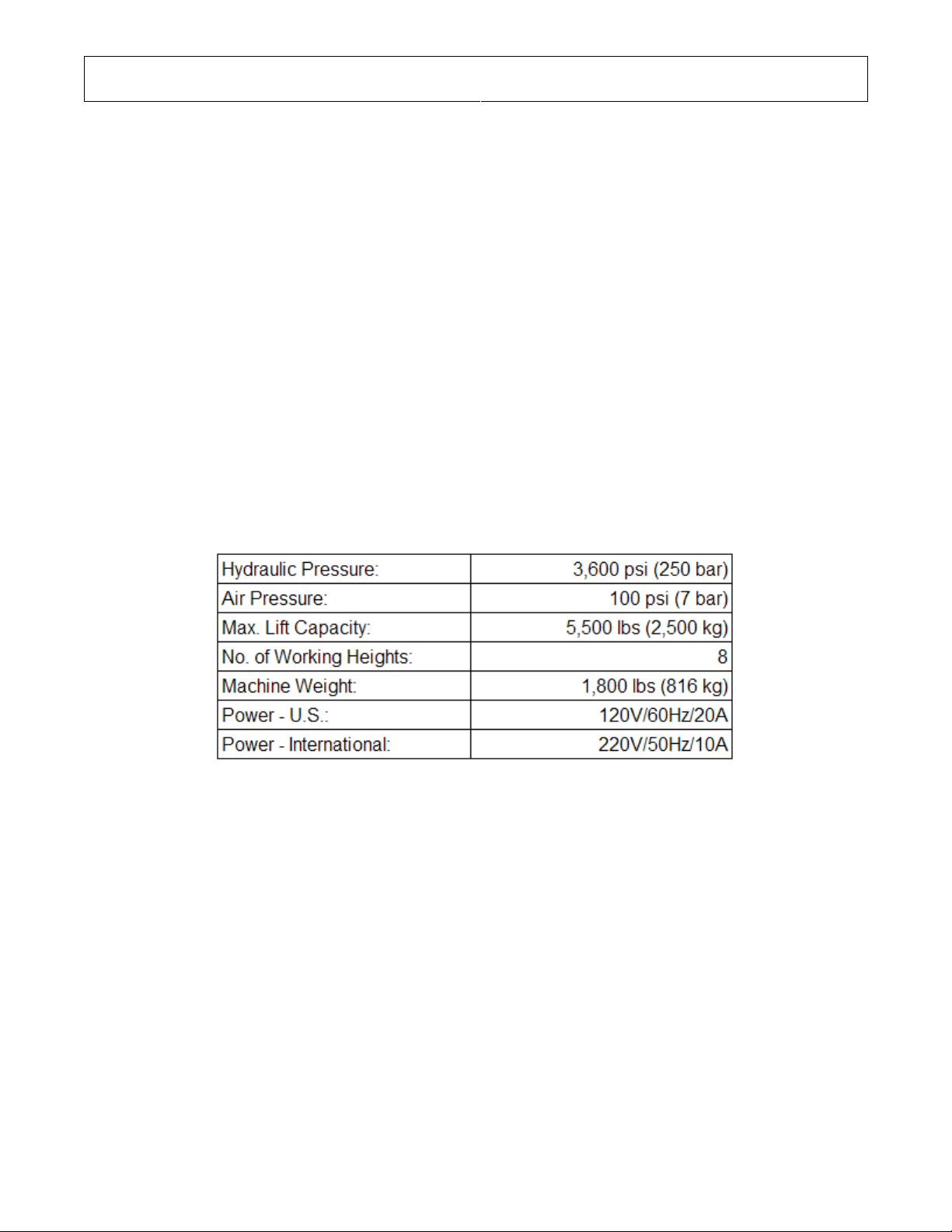
GENERAL SPECIFICATIONS .............................................................................4
INSTALLATION....................................................................................................5
General Information ........................................................................................5
Machine Anchoring .........................................................................................5
Installation Test ...............................................................................................6
OPERATING INSTRUCTIONS.............................................................................7
Safety Procedures...........................................................................................7
Daily Pre-Operation Check .............................................................................8
Controls ...........................................................................................................9
Operation .......................................................................................................10
Owner/Employer Responsibilities: ..............................................................12
Lift Lockout/Tagout Procedure ....................................................................13
Raising Vehicle..............................................................................................15
Lowering Vehicle...........................................................................................16
Anchoring Vehicle (Short Stands) ...............................................................17
Anchoring Vehicle (Optional Tall Stands & Wheel Stands).......................18
Vector Pulling ................................................................................................20
Attaching the Vector Pulling Arm to the Deck ........................................20
Basic Pulling Setup ...................................................................................20
Pulling Setup Examples ............................................................................22
Foot Pump Assembly ................................................................................23
MAINTENANCE .................................................................................................24
Periodic Maintenance Schedule...................................................................24
Daily Pre-Operation Check ...........................................................................24
Monthly Maintenance....................................................................................24
Chain Maintenance........................................................................................25
Refilling Hydraulic Fluid Reservoirs............................................................25
Priming the Foot Pump.................................................................................26
TROUBLESHOOTING .......................................................................................27

CHIEF'S LIMITED ONE-YEAR
WARRANTY & LIABILITY
Chief Automotive Technologies warrants for one year from date of installation
and/or purchase any of its products which do not perform satisfactorily due to
defect caused by faulty material or workmanship. Chief’s obligation under this
warranty is limited to the repair or replacement of products which are defective
and which have not been misused, carelessly handled, or defaced by repair or
repairs made or attempted by others.
CHIEF AUTOMOTIVE TECHNOLOGIES DOES NOT ASSUME RESPONSI-
BILITY FOR ANY DEATH, INJURY OR PROPERTY DAMAGE RESULTING
FROM THE OPERATOR’S NEGLIGENCE OR MISUSE OF THIS PRODUCT
OR ITS ATTACHMENTS. CHIEF MAKES NO WRITTEN, EXPRESS OR
IMPLIED WARRANTY WHATSOEVER OF MERCHANTABILITY OR FITNESS
FOR A PARTICULAR PURPOSE OR OTHERWISE REGARDING THE
EQUIPMENT OR ANY PART OF THE PRODUCT OTHER THAN THE LIMIT-
ED ONE-YEAR WARRANTY STATED ABOVE.
KAHUNA
USERS MANUAL
2

KAHUNA
Users Manual
3
GENERAL SAFETY INSTRUCTIONS
This summary describes physical and chemical processes that may cause injury or death to
personnel, or damage to equipment if not properly followed. This safety summary includes
general safety precautions and instructions that must be understood and applied during
operation and maintenance to make sure that personnel safety and protection of equipment is
observed. Prior to performing any task, the WARNINGs, CAUTIONs, and NOTEs included in
that task should be reviewed and understood.
Warnings, Cautions, and Notes
WARNINGs and CAUTIONs are used in this manual to highlight operating or maintenance
procedures, practices, conditions or statements that are considered essential to protection of
personnel (WARNING) or equipment (CAUTION). WARNINGs or CAUTIONs immediately
precede the step or procedure to which they apply. NOTEs are used in this manual to highlight
operating or maintenance procedures, practices, conditions or statements that are not
essential to the safeguarding of personnel or equipment. NOTEs may precede or follow the
step or procedure, depending on the information to be highlighted. The Headings used and
their definitions are as follows.
WARNING
Highlights essential operating or maintenance procedure, practice, condition, statement, etc.
that if not strictly observed, could result in injury to, or death of, personnel or long term health
hazards.
CAUTION
Highlights essential operating or maintenance procedure, practice, condition, statement, etc.
that if not strictly observed, could result in damage to, or destruction of equipment.
NOTE:
Highlights essential operating or maintenance procedure, practice, condition, or statement.

KAHUNA
Users Manual
4
GENERAL SPECIFICATIONS

KAHUNA
Users Manual
5
INSTALLATION
General Information
1. Any freight damage must be noted on the freight bill before signing and reported to the
freight carrier with a freight claim established. Identify the components and check for
shortages. If shortages are discovered, contact your distributor immediately.
2. Consult building owner and / or architect’s plans when applicable to establish the best
lift location. The lift should be located on a relatively level floor with 4 in. minimum
thickness, 3000-psi concrete slab that has been properly cured.
3. Make sure that the area where the lift will be located is free of obstructions for 12 ft.
above the floor. This includes heaters, building supports, conduits, etc.
4. Make sure there is adequate space to allow movement around the lift with a vehicle in
place.
Machine Anchoring
1. Anchors must be installed at least 5-11/16” from any edge or seam in concrete.
2. The concrete must be at least 4” thick with a compressive strength of 3000psi.
3. Use a hammer drill with a carbide tip, ¾” diameter solid drill bit. The bit tip diameter
should be to ANSI Standard B95.12-1977 (.775” to .787”).
Fig. 1 Fig. 2 Fig. 3
4. Keep drill perpendicular to the floor while drilling. Let drill do the work. Drill the hole
completely through the slab or a minimum 5 inches deep. Clean dust from hole. (See
Figure 1)
5. Using a hammer, carefully tap the anchor bolts into the concrete until the washer rests
against the base plate.(See Figure 2)
6. Tighten the anchor bolts to 95 to 120 ft-lbs. Do not use an impact wrench on anchor
bolts. (See Figure 3)

KAHUNA
Users Manual
6
Installation Test
Test the Lift operation by doing the following (requires a vehicle on the lift):
1. Push “up” switch to a position where the vehicle is just leaving the ground.
2. Raise lift only HALF WAY then lower completely at least one dozen times.
3. Raise lift to its extreme position and inspect. Make sure that there are no hydraulic
leaks. Test mechanical locks. Make sure that the lift holds vehicle in steady position
without lowering.
4. Raise lift slightly and push lock release button. Check that lift lowers smoothly and at a
safe speed.
5. Repeat above procedures to make sure that lift is operating normally.
NOTE: During the initial testing, the lift will descend slowly. This is normal. It helps to add a
payload, no greater than 500 pounds to help speed up the decent during this process.
6. Check all hoses for leaks. Tighten if necessary.

KAHUNA
Users Manual
7
OPERATING INSTRUCTIONS
Safety Procedures
WARNING Failure to adhere to the following can result in death or injury, or damage to
the equipment and vehicle. All personnel will be made aware of this warning and trained in the
use and care of the lift.
1. Never allow unauthorized persons to operate lift. Thoroughly train new employees in the
use and care of lift.
2. Lift should only be operated on a level foundation.
3. Caution - the power unit operates at high pressure.
4. Remove passengers before raising vehicle.
5. Prohibit unauthorized persons from being in shop area while lift is in use.
6. Do not exceed the lift’s capacity.
7. Prior to lifting vehicle, walk around the lift and check for any objects that might interfere
with the operation of lift, such as tools, air hoses, and shop equipment. Remove any
potential obstacles that might impede roller travel.
8. Always lift vehicle using all four pads.
9. Never use lift to raise one end or one side of vehicle.
10. Raise vehicles about three inches and check stability by rocking.
11. Always lock the lift before going under the vehicle. Never allow anyone to go under the
lift when raising or lowering.
12. The vehicle’s center of gravity should be balanced on the lift.
13. Do not remove heavy components from a raised machine or vehicle without first
installing adequate supports. The vehicle may become unbalanced and fall.

KAHUNA
Users Manual
8
Daily Pre-Operation Check (8-Hours)
NOTE: Occupational Safety and Health Administration (OSHA) and the American National Standards
Institute (ANSI) require users to inspect lifting equipment at the start of every shift. These and other
periodic inspections are the responsibility of the user.
WARNING Failure to perform the daily pre-operational check can result in expensive
property damage, lost production time, serious personal injury, and even death. The safety
latch system must be checked and working properly before the lift is put to use.
The daily pre-operational check consists of the following:
1. Check hydraulic connections, and hoses for leakage.
2. Make sure all bolts are secured and snug with lock washer, nylon lock nuts, or cotter
keys.
3. Test the lift locking mechanism for proper operation.
4. Check oil level in pump reservoir.
5. Always keep the lift platforms clean and do not use the lift if it has oil, dirt or mud on it.

KAHUNA
Users Manual
9
Controls

KAHUNA
Users Manual
10
Operation
Operate the lift as given in the following paragraphs.
Safety label artwork courtesy of Automotive Lift Institute – www.autolift.org

KAHUNA
Users Manual
11
Safety label artwork courtesy of Automotive Lift Institute – www.autolift.org

KAHUNA
Users Manual
12
The Owner/Employer:
• Shall ensure that lift operators are qualified and that they are trained in the safe use and
operation of the lift using the manufacturer’s operating instructions; ALI/SM01-1, ALI
Lifting it Right safety manual; ALI/ST-90 ALI Safety Tips card; ANSI/ALI ALOIM-2000,
American National Standard for Automotive Lifts-Safety Requirements for Operation,
Inspection and Maintenance; ALI/WL Series, ALI Uniform Warning Label
Decals/Placards; and in the case of frame engaging lifts, ALI/LP-GUIDE, Vehicle Lifting
Points/Quick Reference Guide for Frame Engaging Lifts.
• Shall establish procedures to periodically inspect the lift in accordance with the lift
manufacturer’s instructions or ANSI/ALI ALOIM-2000, American National Standard for
Automotive Lifts-Safety Requirements for Operation, Inspection and Maintenance; and
The Employer Shall ensure that lift inspectors are qualified and that they are adequately
trained in the inspection of the lift.
• Shall establish procedures to periodically maintain the lift in accordance with the lift
manufacturer’s instructions or ANSI/ALI ALOIM-2000, American National Standard for
Automotive Lifts-Safety Requirements for Operation, Inspection and Maintenance; and
The Employer Shall ensure that lift maintenance personnel are qualified and that they
are adequately trained in the maintenance of the lift.
• Shall maintain the periodic inspection and maintenance records recommended by the
manufacturer or ANSI/ALI ALOIM-2000, American National Standard for Automotive
Lifts-Safety Requirements for Operation, Inspection and Maintenance.
• Shall display the lift manufacturer’s operating instructions; ALI/SM 93-1, ALI Lifting it
Right safety manual; ALI/ST-90 ALI Safety Tips card; ANSI/ALI ALOIM-2000,
American National Standard for Automotive Lifts-Safety Requirements for Operation,
Inspection and Maintenance; and in the case of frame engaging lifts, ALI/LP-GUIDE,
Vehicle Lifting Points/Quick Reference Guide for Frame Engaging Lifts; in a
conspicuous location in the lift area convenient to the operator.
• Shall provide necessary lockout/tagout means for energy sources per ANSI Z244.1-
1982 (R1993), Safety Requirements for the Lockout/Tagout of Energy Sources, before
beginning any lift repairs.
• Shall not modify the lift in any manner without the prior written consent of the
manufacturer.

KAHUNA
Users Manual
13
Lift Lockout/Tagout Procedure
Purpose
This procedure establishes the minimum requirements for the lockout of energy that could
cause injury to personnel by the operation of lifts in need of repair or being serviced. All
employees shall comply with this procedure.
Responsibility
The responsibility for assuring that this procedure is followed is binding upon all employees
and service personnel from outside service companies (i.e., Authorized Installers, contractors,
etc.). All employees shall be instructed in the safety significance of the lockout procedure by
the facility owner/manager. Each new or transferred employee along with visiting outside
service personnel shall be instructed by the owner/manager (or assigned designee) in the
purpose and use of the lockout procedure.
Preparation
Employees authorized to perform lockout shall ensure that the appropriate energy isolating
device (i.e., circuit breaker, fuse, disconnect, etc.) is identified for the lift being locked out.
Other such devices for other equipment may be located in close proximity of the appropriate
energy isolating device. If the identity of the device is in question, see the shop supervisor for
resolution. Assure that proper authorization is received prior to performing the lockout
procedure.
Sequence of Lockout Procedure
1) Notify all affected employees that a lockout is being performed and the reason for
it.
2) Unload the subject lift. Shut it down and assure the disconnect switch is “OFF” if
one is provided on the lift.
3) The authorized lockout person operates the main energy isolation device
removing power to the subject lift.
•If this is a lockable device, the authorized lockout person places the assigned
padlock on the device to prevent its unintentional reactivation. An appropriate
tag is applied stating the person’s name, at least 3” x 6” in size, an easily
noticeable color, and states not to operate device or remove tag.
•If this device is a non-lockable circuit breaker or fuse, replace with a “dummy”
device and tag it appropriately as mentioned above.
4) Attempt to operate lift to assure the lockout is working. Be sure to return any
switches to the “OFF” position.

KAHUNA
Users Manual
14
Restoring Equipment to Service
1) Assure the work on the lift is complete and the area is clear of tools, vehicles, and
personnel.
2) At this point, the authorized person can remove the lock (or dummy circuit breaker or
fuse) & tag and activate the energy isolating device so that the lift may again be placed into
operation.
Rules for Using Lockout Procedure
Use the Lockout Procedure whenever the lift is being repaired or serviced, waiting for repair
when current operation could cause possible injury to personnel, or for any other situation
when unintentional operation could injure personnel. No attempt shall be made to operate the
lift when the energy isolating device is locked out.

KAHUNA
Users Manual
15
Raising Vehicle
Raise the vehicle as follows:
1. Drive vehicle onto the lift and check if the vehicle is placed in appropriate position.
Relocate vehicle as required.
NOTE: Some vehicles may have the manufacturer's Service Garage Lift Point locations
identified by triangle shape marks on it's undercarriage (reference ANSI/SAE J2184-1992).
Also, there may be a label located on the right front door lock face showing specific vehicle lift
points. If the specific vehicle lift points are not identified, refer to the "Typical Lift Points"
illustrated herein or the ANSI/ALI Lifting Point Guide included with your lift. ALWAYS follow
the operating instructions supplied with the lift.
Typical Lift Points Diagram
2. Position the four lift arms at the appropriate places on the deck to allow the arms and
pads to swing underneath the lifting points.
3. Locate lift pads at appropriate lifting points under vehicle.
4. Push “up” switch until the lift reaches a position to where the vehicle is just leaving the
ground.
5. Inspect to make sure there is no interference with any other objects.
6. Check proper engagement of lifting pads on vehicle. Make sure that vehicle is horizontal
on lift.
7. Shake moderately at front or rear bumper.
8. Raise vehicle to desired height then lower onto lock. Make sure that the lift holds the
vehicle in steady position without lowering.
WARNING Failure to heed the following step can result in serious personal injury.
9. Disconnect electrical power to make sure lift is not inadvertently activated while working
on vehicle.

KAHUNA
Users Manual
16
Lowering Vehicle
Lower the vehicle by doing the following:
1. Prior to lowering vehicle, walk around the lift and check for any objects that might
interfere with the operation of lift such as tools, air hoses, and shop equipment.
2. Reconnect electrical power to the power unit.
3. Raise lift slightly and push lock release button.
4. Check that lift lowers smoothly and at a safe speed.
5. Allow the lift to fully lower and lock the lift.
6. Swing the arms out of the way and slowly drive the vehicle out. Have some one outside
the vehicle guide the driver.

KAHUNA
Users Manual
17
Anchoring Vehicle (Short Stands)
1. Position the vehicle over the lift with the vehicle’s center of gravity centered over the lift.
2. Place the anchoring arms on the deck directly below the desired anchoring points.
3. Position the short anchoring assemblies on the anchoring arms.
4. Raise the lift just high enough for the pinchwelds to settle into the clamps. Tighten the
pinchweld clamps.
5. Raise the lift just high enough to be able to bolt the anchor assemblies to the anchoring
arms. Secure the anchor assemblies to the anchoring arms with the plate and bolt
provided.
6. Secure the anchoring arms to the deck with the brackets and bolts provided.
CAUTION Do not raise the lift to working heights without fully securing the anchoring
components to the deck.
7. Reverse the previous steps to remove the vehicle from the lift.

KAHUNA
Users Manual
18
Anchoring Vehicle (Optional Tall Stands & Wheel Stands)
1. Position the vehicle over the lift with the vehicle’s center of gravity centered over the lift.
2. Follow the lift procedures in this manual to raise the vehicle.
3. Raise the vehicle just high enough to slide the optional wheel stands under each tire.
4. Lower the lift until the wheel stands are supporting the vehicle. Be sure that the load on
the wheel stands is stable before lowering the lift further.
5. Remove the lift arms from the deck of the machine.
6. Determine the four points where the vehicle will be anchored and install the anchoring
arms on the deck below those points. Be sure to secure the anchoring arms to the deck
with the brackets and bolts provided.
Table of contents
Other CHIEF Lifting System manuals

CHIEF
CHIEF SMART-LIFT SL151i User manual

CHIEF
CHIEF SMART-LIFT SL236i User manual

CHIEF
CHIEF CM2C40 User manual

CHIEF
CHIEF Pit Boss 638699 User manual

CHIEF
CHIEF SMART-LIFT SL-236 User manual

CHIEF
CHIEF CM2L40 User manual

CHIEF
CHIEF CM2L40U User manual

CHIEF
CHIEF EZ LINER EXPRESS User manual

CHIEF
CHIEF CM2C40U User manual
Popular Lifting System manuals by other brands

Ravaglioli
Ravaglioli RAV1150U instructions

HADEF
HADEF 20/94AF-EX Installation, Operating and Maintenance Instruction

ergolet
ergolet Stellar/170 User instruction

APlusLift
APlusLift MT1500 Installation manual & operation instructions

Tractel
Tractel corso PT 0,5 Original Operation and Installation Manual

ATT NUSSBAUM
ATT NUSSBAUM COMBI LIFT 4.40 S Operating manual, Inspection book