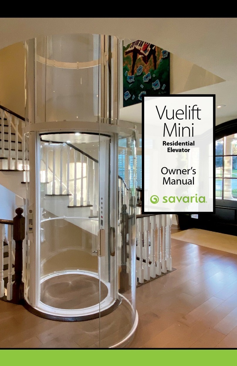
LIFTSHOP Q1 User manual

Q1 User
Manual and
Service
Guide
Residential Elevator

Thank you for
choosing the
Pollock Lifts
Residential
Elevator
Contents
Warnings 3
1 Drive systems, features and controls 4
Drive systems
Elevator sizes and options
Seating
Control panel
Remote call station
Hard-wired call station
2 Safety features 7
Door
Upper sensitive edge
Bottom tray
Smart display
3 Using your elevator 8
4 Other features 10
Short-term shut off
Long-term shut off
Periodic examination
Periodic servicing
5 Servicing and fault finding 11
If the elevator fails to operate
What you should do if...
6 In case of an emergency 13
Emergency lowering of the elevator
Emergency opening of the elevator door
7 Technical details 17
Please read through all sections carefully to familiarise
yourself fully with your new elevator.
Bringing you
quality and
excellence
for all your
future needs

3
WARNINGS
Do not turn the mains power supply switch off.
Do not stand under the elevator when it is descending.
Do not stand on the trapdoor when the elevator is ascending.
Do not attempt to open the elevator door when the elevator
is in motion.
Do not allow children to use the elevator unsupervised.
Do not manually open or move the elevator during a fire as
this could result in abrupt spreading of the fire.
Do not exceed the recommended safe working load of
40 stone or 255kg.
Never attempt to exit the elevator if for any reason the elevator
should fail to reach a stop. Use the yellow alarm button, phone
or autodialler (if fitted) to gain assistance.
Never attempt to climb out of a moving or stationary elevator –
call for assistance, manually lower the elevator, and then manually
open elevator door before exiting.
Never attempt to exit the elevator should the safety gear trigger.
It is recommended you wait for an approved Service Engineer
who will safely assist you from the elevator.
Safety gear, if triggered, must be reset by an approved Service
Engineer ONLY. An approved Service Engineer in this context,
is a competent person with the necessary tools, instructions,
appropriate training and sufficient experience of the equipment.
Built for your specific needs and requirements, your new
elevator will provide you with many years trouble free use,
and this handbook indicates the main features and functions
for all users.
Always keep area
of the lift car travel
clear of obstructions

Drive systems, features and controls
Drive systems
Traction
An electric motor is located at the top of the tracks at the first floor
ceiling level, and is attached to the elevator with steel cables.
Hydraulic
A hydraulic cylinder is located centrally between the lower tracks,
with the pump unit located in a convenient position within 6m of
the elevator.
Elevator sizes and options
The Pollock Lifts Residential Elevator is available in a range of
sizes and configuration options.
Seating
Tip-up seat
The seat can be fixed directly to the back of the lift car.
It has a carrying capacity of 200kg or 31 stone.
The seat is designed so it can be tipped up to allow access for
a wheelchair.
All models with seats have a seatbelt fitted to secure the user in
position when the elevator is in motion. These operate in a similar
fashion to a car seatbelt.
1

5
Control panel
Located inside on the rear panel, or on the left or right side
rails of the elevator, the main control panel buttons perform
the following operations.
Open and close the door
The door button will release the lock mechanism when the lift is parked
at the upper or lower level, allowing the door to be opened manually.
The door will open and close automatically if a power door mechanism
has been fitted.
Travel upwards – latching button – press and hold until elevator moves.
Travel downwards – latching button – press and hold until elevator moves.
Yellow button – activate the alarm
If specified, calls the first number on the autodialler.
Red button – stop the elevator at any time
Remote call station
Located on a wall adjacent to the elevator itself, the battery
powered removable call station allows the following operations
to be performed from outside the elevator.
Lock and unlock the door – open and close where power door
mechanism has been fitted.
Travel upwards – latching button – press and hold until elevator moves.
Travel downwards – latching button – press and hold until elevator moves.
Yellow button – switch off alarm
Red button – stop the elevator at any time

6
Key switch (left)
Switches lift On/Off
Key switch (right)
Enables DC lowering
Hard-wired call station
Located on a wall adjacent to the elevator itself, the fixed
call station allows the following operations to be performed
from outside the elevator.
Lock and unlock the door – open and close where power door
mechanism has been fitted.
Travel upwards
Travel downwards
Yellow button – switch off alarm
Red button –stop the elevator at any time
Latching button – turn clockwise to release.
The On/Off key switch must be turned ‘ON’ and the second key
switch must be at position ‘1’ in order for the elevator to operate.

7
Safety features
Door
The door has a fully secure interlock which is opened automatically
at the landing, or by the buttons outside the elevator, and again from
the control panel inside the elevator.
Upper sensitive edge
The upper sensitive surface fully covers the top of the elevator. This is
a safety measure to prevent trapping between the elevator and the
ceiling as the elevator ascends. Light pressure on the sensitive surface
will immediately stop the elevator, which can then move downwards
away from the obstruction.
Bottom tray
The bottom tray closes the ceiling aperture to create a fire seal when
the elevator is at the upper level. The bottom tray also acts as a sensitive
surface when the elevator is descending. Should an obstruction below
the elevator be encountered, the spring loaded tray will activate the safety
switches forcing the elevator to stop immediately. The elevator will then
only move upwards away from the obstruction.
Conversely, if an obstruction is detected as the elevator is ascending,
the separation switch will activate and stop in up direction. The elevator
will then only move downwards away from the obstruction.
Smart display
At Pollock Lifts we are leaders in the introduction of the innovative
service and fault finding control, through the use of our unique on board
LCD display (optional) which is located at the rear of the elevator.
This will allow the user to see the status of the elevator and can
be used for diagnostic checks and maintenance by the user and our
engineering product support team.
2

Using your elevator
Move the lift from outside the elevator
Press and hold the blue up button or the green down button
on the remote call station until the lift begins to move.
Open the door from outside the elevator
Press the illuminated door button on the side of the elevator,
or on the call station. Either option unlocks the door allowing
it to be opened.
If a power door mechanism is fitted it will open automatically.
Enter the elevator
Hold on to the elevator’s rail if standing, or position yourself
comfortably on the elevator seat.
Close the door from inside the elevator
Pull the door closed, or if your elevator is fitted with a power door
mechanism, press the open and close door button on the control
panel in the elevator.
In both cases, when the door is closed the lock will engage.
Prepare to travel
If using the elevator seat please fit the seatbelt provided for extra
security. This operates in the same manner as a car seatbelt.
Travel upwards
Press and hold the button with arrow facing up on the control panel
until the elevator begins to move.
Travel downwards
Press and hold the button with arrow facing down on the control panel
until the elevator begins to move.
Stop elevator
Press the red button on the control panel.
3

9
Make sure to keep
your elevator, and the
elevator tracks clean
Sound alarm
Press the yellow button on the control panel.
In-car phone
Use the phone as you would your household phone.
Autodialler operation
The autodialler is similar to a telephone, and is activated by pressing
the alarm button.
The autodialler will begin to call the pre-programmed contact numbers.
Wipe your elevator, and the elevator tracks using a damp
cloth with a little washing up liquid. The panels, glass, and
tracks should be cleaned once a fortnight.

Other features
Lock Lift
If the elevator needs to be made inoperable for a short
period of time the following procedure should be followed.
Traction model
Move elevator to the first floor and press and hold the blue up
button for 10 seconds. The display will show lift car locked.
To unlock, press and hold the blue up button for 10 seconds.
Hydraulic model
Move elevator to the ground floor and press and hold the green
down button for 10 seconds. The display will show lift car locked.
To unlock, press and hold the blue up button for 10 seconds.
Long-term shut off
If the elevator is to be rendered inoperable for longer periods of
time, please contact your service provider.
Periodic examination
Once installation is complete and the elevator has been
commissioned, the service counter will be set to ZERO and
the LCD display will inform you when your next service is
due if required earlier than at six monthly intervals.
If necessary, the Engineer may recommend more frequent
examinations to ensure continued safe and reliable operation.
Any recommended repairs will be noted, including a time scale
for completion.
Should a defect directly affecting safety which requires immediate
repair be reported, the elevator will have to be taken out of service.
Any maintenance or service should be recorded in the elevator’s
service log.
Periodic servicing
The elevator should be thoroughly serviced by a competent
person within six months of commissioning and thereafter at
intervals not exceeding six months.
NOTE!
Call outs and service visits may be combined to minimise
disruption. At each service any serious defects should be rectified,
and Engineering Test carried out and logged.
4

11
Servicing and fault finding
If the elevator fails to operate
Please contact the Service Engineer immediately should any
of the following occur:
Activation of the emergency brake, Malfunction of the fire system or
Unusual noises coming from the lift.
Check the display at the back of the elevator, which will show a message
relating to the fault, and contact the Service Engineer informing them of
the fault display message.
Lifts with a monochrome display, the faults and resolutions are detailed below.
Lifts with a full colour display, the faults and resolutions are shown graphically
on the screen.
LCD display message Possible cause Advised action
Stop Btn Pressed Stop button pushed in – in the car or
call station Check button
Mains off Mains off Check mains is on
Carrier Safety Call Engineer
Slack Ropes Call Engineer
Final Limit Sw Call Engineer
Over Speed Sw Call Engineer
Hand-Wind Switch Call Engineer
External Stop Stop button pressed on wired wall box Check button
Drive Fault Call Engineer
Over Travel Sw Call Engineer
Pressure Switch The lift has exceeded its load capacity
(Hydraulic ONLY)
Ensure carrying
capacity has not
been exceeded
Door Lock Fault Door lock has not locked Open+close door
Up Edge Left Safety edge has been impeded going up
Remove obstacle
and ensure edge
can move freely
Up Edge Back Safety edge has been impeded going up
Up Edge Right Safety edge has been impeded going up
Up Edge Door Safety edge has been impeded going up
Tray Sep Left Bottom tray has been impeded going up
Tray Sep Right Bottom tray has been impeded going up
Tray Safety Left Bottom tray has been impeded going down
Tray Safety Right Bottom tray has been impeded going down
Trapdoor Up Sw Trapdoor has been impeded going up
Trapdoor Down Sw Trapdoor has been impeded going down
Tray Separation Fault A spring holding the tray has failed Call Engineer
Trapdoor Fault Trapdoor has failed to move with the lift car Call Engineer
Lift Locked Up or down button has been pressed down
outside the elevator for 10 seconds
Press and hold
up or down button
for 10 seconds
5

12
What you should do if…
The elevator door fails to open
Ensure that the elevator is in the fully raised position, or in the fully lowered
position, by checking the LCD display at the back of the elevator.
Press and hold the up or down button on the control panel to ensure that
the full travel of the elevator has been completed.
The elevator will automatically stop at the correct position.
If the door still won’t open, follow the Emergency opening of
the elevator door procedure.
The alarm needs to be turned off
Press the yellow alarm button on the control panel.
A single press of the yellow alarm button will silence the alarm.
The LCD display will return to its home screen.
The smoke alarm needs to be turned off
Press the yellow alarm button on the remote call station.
A single press of the yellow alarm button will silence the alarm.
The red LED on the smoke detector will turn off and the alarm will
sound briefly.
The LCD display will return to its home screen.
Power failure
If a power failure should occur while the elevator is in motion, both
the hydraulic and traction elevators are fitted with an emergency lowering
system which allows you to lower the lift. This permits one travel downwards
and no upwards travel. This is only active for one hour after power failure.
To activate this simply press and hold the down button, on
the internal control panel.
The elevator will begin to descend after approximately five seconds.
All safety features will operate as normal.
We recommend that the elevator remains parked at the lower level
until power is restored.
If ever in doubt
please call the
Service Engineer

13
6
In case of an emergency
Emergency lowering of the elevator
You can lower the elevator by using one of the following
methods. Please call your Service Engineer if you are
unsure of how to complete the actions detailed below.
WARNING
Emergency lowering disables all lift safety edges, and as such
there is a crushing risk to people or objects outside the lift.
Emergency lowering should only be used when the area is clear
of people or obstacles, and the elevator can be fully monitored
during the full descent.Two people may be required.
Traction – Option 1 (Radio Control)
Ensure area underneath the elevator is clear of people and obstacles.
Switch off power supply to the elevator by turning off the mains power
switch, located on the wall beside the motor mount.
Remove the remote call station’s battery cover.
Press and hold the hidden button beside the battery.
Whilst continuing to hold the hidden button press and hold the green
down button – allow 15 - 20 seconds. The elevator will descend whilst
both buttons are pressed simultaneously.
Once the elevator has reached the ground floor both buttons may
be released.
Refit the battery cover.
Hidden button

14
WARNING
Emergency lowering disables all lift safety edges, and as such
there is a crushing risk to people or objects outside the lift.
Emergency lowering should only be used when the area is clear
of people or obstacles, and the elevator can be fully monitored
during the full descent.Two people may be required.
Traction - Option 2 (Hard-wired)
Ensure area underneath the elevator is clear of people and obstacles.
Switch off the mains power switch, located on the wall beside
the motor mount.
Remove the hand-winder access cover.
Insert the hand-winding wheel into the hole in the motor mount cover.
You should feel the hand-winding wheel locate onto an internal shaft.
Pull back on the brake release lever and simultaneously rotate
the hand wind wheel in the required direction of travel.
NOTE! It is easier to wind down than up.
When the lift car has reached floor level remove the hand winding wheel.
Traction - Option 3 (Hard-wired)
Ensure the area underneath the elevator is clear of people and obstacles.
Switch off the mains power switch, located on the wall beside
the motor mount.
Turn the On/Off key switch to position ‘0’.
Turn the DC lowering key switch to position ‘1’ and hold.
After 5 seconds the elevator will begin to descend.
Once the elevator has reached the ground floor release the key.

15
WARNING
Emergency lowering disables all lift safety edges, and as such
there is a crushing risk to people or objects outside the lift.
Emergency lowering should only be used when the area is clear
of people or obstacles, and the elevator can be fully monitored
during the full descent.Two people may be required.
Hydraulic
Ensure area underneath the elevator is clear of people and obstacles.
Pull out and hold the red emergency release knob, located on
the pump unit. This will allow the lift to descend slowly.
When the elevator has reached floor level, release the emergency
release knob.
Hydraulic release valve

16
Emergency opening of the elevator door
Do not open the door unless the elevator is correctly positioned
at the upper or lower landing.
Locate the release slot on the elevator’s side, just above the door button.
Insert the release key supplied into the bottom of the slot and lift
upwards to release the door lock mechanism.
Release slot
Door button
Release key

7
Technical details
Specifications
Serial number
Date of manufacture
Lift type

Notes


Get in touch for more information
Pollock Lifts
1 Sloefield Drive
Trooperslane Industrial Estate
Carrickfergus
Co. Antrim
BT38 8GX
United Kingdom
T028 9336 8167
www.pollocklifts.co.uk
Version 3: Apr19
Pollock Lifts seeks to continually improve its products; therefore the information in this brochure may be subject to change.
Part number 25900950
Document design by The Design Factor, Belfast
Table of contents