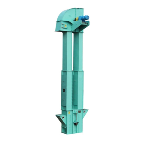
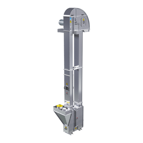
GSi Bucket Elevator II Series User manual

PNEG-681
Series II Bucket Elevator
Assembly Manual
PNEG-681
Version: 2.2
Date: 12-21-20

2PNEG-681 Series II Bucket Elevator
Use of the equipment information page will help you identify the equipment in the case that you need to notify the
company. For this reason, this information should be filled out and kept on record.
Equipment Information
Model Number: ______________________________________________
Serial Number: ______________________________________________
RPM: _____________________________________________________
Head Pulley Diameter: ________________________________________
Discharge Height: ____________________________________________
Horsepower: ________________________________________________
GSI Group
1004 E. Illinois St.
Assumption, IL. 62510
Phone: 1-217-226-4421
Date Purchased: ___________________________________________
Dealer Name and Phone Number: ________________________________
________________________________
________________________________
All information, illustrations, photos and specifications in this manual are based on the latest
information available at the time of publication. The right is reserved to make changes at any
time without notice.

Table of Contents
PNEG-681 Series II Bucket Elevator 3
Contents
Chapter 1 Introduction ..........................................................................................................................................4
General Safety Statements ................................................................................................................... 4
Receiving Inspection ............................................................................................................................. 4
Pre-Installation Notifications .................................................................................................................. 4
Chapter 2 Safety .....................................................................................................................................................5
Safety Guidelines .................................................................................................................................. 5
Cautionary Symbols Definitions ............................................................................................................ 6
Safety Cautions ..................................................................................................................................... 7
Safety Sign-Off Sheet ......................................................................................................................... 11
Chapter 3 Safety Decals ......................................................................................................................................12
Decal Placement ................................................................................................................................. 14
Chapter 4 Elevator Parts .....................................................................................................................................15
Part Identification ................................................................................................................................ 15
Chapter 5 Bucket Elevator Foundation ..............................................................................................................16
Chapter 6 Boot Section .......................................................................................................................................17
Attaching Boot to Foundation .............................................................................................................. 17
Inspection Sections ............................................................................................................................. 18
Chapter 7 Trunking ..............................................................................................................................................19
Standard Trunking ............................................................................................................................... 19
Pressure Relief Trunking ..................................................................................................................... 20
Trunking Installation ............................................................................................................................ 21
Chapter 8 Lower Head Section ...........................................................................................................................22
Head Bonnet Section .......................................................................................................................... 22
Chapter 9 Maintaining Plubmness .....................................................................................................................24
Chapter 10 Belting, Splicing and Buckets .........................................................................................................25
Belts ................................................................................................................................................... 25
Splicing .............................................................................................................................................. 25
Buckets .............................................................................................................................................. 26
Belt Slack Removal ........................................................................................................................... 26
Chapter 11 Drive Motor and Motor Mount .........................................................................................................28
Drive .................................................................................................................................................. 28
Motor Mount Assembly ...................................................................................................................... 28
Slide Base ......................................................................................................................................... 29
Torque Arm ........................................................................................................................................ 30
Shaft Mount Reducer ......................................................................................................................... 31
Drive Guard ....................................................................................................................................... 31
Drive Belts ......................................................................................................................................... 35
Chapter 12 Final Checks, Tracking, Start-Up and Maintenance ......................................................................36
General Final Checks ........................................................................................................................ 36
Belt Tracking ...................................................................................................................................... 37
Start-Up ............................................................................................................................................. 37
Maintenance ...................................................................................................................................... 37
Chapter 13 Appendix 1 - Reference Information ...............................................................................................38
Chapter 14 Warranty ............................................................................................................................................39
4PNEG-681 Series II Bucket Elevator
1. Introduction
Thank you for choosing a GSI product. It has been designed to provide excellent performance andservice
for many years.
This manual covers general information about installing the GSI Bucket Elevator.
Due to the large variety of equipment features offered, this manual cannot cover every aspect of
installation with this manual. This manual provides suggested and recommended methods for installing
the product. GSI recommends you retain a qualified contractor to provide on-site expertise.
GSI is not responsible for the installation of this product.
General Safety Statements
1. Our primary concern is your safety and the safety of others associated with the use of this product.
All personnel responsible for installing, operating or maintaining this equipment should read and
understand this manual. It is the responsibility of the owner to make this manual available to the
person or persons involved with this equipment.
2. Guards and safety labels have been installed prior to leaving the manufacturing plant. These should
not to be removed, altered or defaced in any way.
3. Modifications to equipment may cause extremely dangerous situations that could result in damage
to the equipment as well as serious injury or death. Never modify the equipment.
4. GSI recommends that you contact the local power company to have a representative survey the
installation to ensure wiring is compatible with their system and adequate power is supplied to
the unit.
Receiving Inspection
1. Carefully inspect the shipment for damage as soon as it is received and verify that the quantity of
parts or packages actually received corresponds to the quantity shown on the packing slip.
2. Report any discrepancies, shortages or damages to the delivering carrier as soon as possible.
3. The manufacturer’s responsibility for damage to the equipment ends when the carrier accepts the
equipment for delivery. Refer to the bill of lading for more detailed information.
4. Save all paperwork and documentation furnished with any of the elevator components.
Pre-Installation Notifications
1. GSI is the manufacturer and vendor of the elevator and is responsible only for the optional
accessories also manufactured by GSI.
2. The elevator has not been designed to support other equipment such as cleaners, distributors or
spouting. Separate structures must be provided for any accessory equipment.
3. This installation manual should be used for reference only.
4. The owner/user/installer of this equipment is responsible for consulting and retaining a civil or
structural engineer regarding the design, construction and supervision of the entire installation,
including the elevator foundation and the guying cable and/or bracing system.
5. GSI Bucket Elevators are designed to be vertically self-supporting when erected but must be
supported or guyed against wind loads.

PNEG-681 Series II Bucket Elevator 5
2. Safety
Safety Guidelines
Safety guidelines are general-to-specific safety rules that must be followed at all times. This manual is
written to help you understand safe operating procedures and problems that can be encountered
by the operator and other personnel when using this equipment. Save these safety guidelines for
future reference.
As owner or operator, you are responsible for understanding the requirements, hazards, and precautions
that exist and to inform others as required. Unqualified persons must stay out of the work area at all times.
Alterations must not be made to the equipment. Alterations can produce dangerous situations resulting in
SERIOUS INJURY or DEATH.
This equipment must be installed in accordance with the current installation codes and applicable
regulations,which must becarefully followedinall cases.Authorities havingjurisdiction mustbeconsulted
before installations are made.
When necessary, you must consider the installation location relative to electrical, fuel and water utilities.
Personnel operating or working around equipment must read this manual. This manual must be
delivered with equipment to its owner. Failure to read this manual and its safety instructions is a misuse
of the equipment. ST-0001-3

2. Safety
6PNEG-681 Series II Bucket Elevator
Cautionary Symbols Definitions
Cautionary symbols appear in this manual and on product decals. The symbols alert the user of potential
safety hazards, prohibited activities and mandatory actions. To help you recognize this information, we
use the symbols that are defined below.
DANGER
WARNING
CAUTION
NOTICE
This symbol indicates an imminently hazardous situation
which, if not avoided, will result in serious injury or death.
This symbol indicates a potentially hazardous situation
which, if not avoided, can result in serious injury or death.
This symbol indicates a potentially hazardous situation which,
if not avoided, can result in minor or moderate injury.
This symbol is used to address practices not related to
personal injury.
This symbol indicates a general hazard.
This symbol indicates a prohibited activity.
This symbol indicates a mandatory action.
ST-0005-2

2. Safety
PNEG-681 Series II Bucket Elevator 7
Safety Cautions
Use Personal Protective Equipment
Eye
Protection
Hearing
Protection
Hand
Protection
Head
Protection
Respiratory
Protection Foot
Protection
Fall
Protection
• Use appropriate personal protective equipment:
• Wear clothing appropriate to the job.
• Remove all jewelry.
• Tie long hair up and back.
ST-0004-1
Follow Safety Instructions
• Carefully read all safety messages in this manual and safety
signs on your machine. Keep signs in good condition. Replace
missing or damaged safety signs. Be sure new equipment
components and repair parts include the current safety signs.
Replacement safety signs are available from the manufacturer.
• Learn how to operate the machine and how to use
controls properly. Do not let anyone operate without instruction.
• If you do not understand any part of this manual or need
assistance, contact your dealer.
ST-0002-1

2. Safety
8PNEG-681 Series II Bucket Elevator
Maintain Equipment and Work Area
• Understand service procedures before doing work. Keep area
clean and dry.
• Never service equipment while it is operating. Keep hands, feet,
and clothing away from moving parts
• Keep your equipment in proper working condition. Replace worn
or broken parts immediately.
ST-0003-1
Sharp Edge Hazard
• This product has sharp edges, which can cause serious injury.
• To avoid injury, handle sharp edges with caution and always use
proper protective clothing and equipment.
ST-0036-2
Stay Clear of Rotating Parts
• Do not service equipment while it is in operation.
• Entanglement in rotating parts or exposed belts will cause serious
injury or death.
• Keep all shields and covers in place at all times.
• Lock-out power source before making adjustments, cleaning,
or maintaining equipment.
ST-0072-1

2. Safety
PNEG-681 Series II Bucket Elevator 9
Stay Clear of Moving Parts
• Entanglement in rotating sprocket or moving chain will cause
serious injury or death.
• Keep all guards and covers in place at all times.
• Lock-out power source before making adjustments, cleaning,
or maintaining equipment.
ST-0076-1
Operate Motor Properly
• All electrical connections must be made in accordance with
applicable local codes (National Electrical Code for the US,
Canadian Electric Code, or EN60204 along with applicable
European Directives for Europe). Make sure equipment and
bins are properly grounded.
• Lock-out power before resetting motor overloads.
• Do not repetitively stop and start the drive in order to free a
plugged condition. Jogging the drive in this manner can damage
the equipment and drive components.
ST-0009-3
Fall Hazard
• Keep access door closed while on a platform to avoid falls.
• Always use proper personal protective equipment and proper
clothing when using equipment. Failure to follow safety
precautions can result in severe injury or death.
ST-0042-2
Stay Clear of Hoisted Equipment
• Always use proper lifting or hoisting equipment when assembling
or disassembling equipment.
• Do not walk or stand under hoisted equipment.
• Always use sturdy and stable supports when needed for
installation. Not following these safety precautions creates the
risk of falling equipment, which can crush personnel and cause
serious injury or death.
ST-0047-1

2. Safety
10 PNEG-681 Series II Bucket Elevator
Fall Hazard
• Ladders, stairways and platforms are for use by competent
and trained personnel only. Do not allow children or other
unauthorized persons to have access to the equipment.
• Access to the equipment must be restricted by the use of security
fencing and lockable gates.
• Lower sections of ladders must be fitted with a lockable safety
gate to prevent unauthorized access.
• Make sure that hot surfaces have had adequate time to cool
before working on or in the equipment.
• Lock out and tag out power supplies and fuel supplies to all
equipment.
• Do not attach lifting equipment to ladders or platforms.
• Do not go outside of the safety rails provided on elevated
platforms.
• Do not work at heights during high winds, rain, snow, or ice
storms.
ST-0056-1
Toxic Fume and Dust Hazard
• Do all work outside or in a well-ventilated area. Dispose of paint
and solvent properly.
• Remove paint before welding or heating:
— Avoid potentially toxic fumes and dust. Hazardous fumes can
be generated when paint is heated by welding, soldering, or
using a torch.
— If you sand or grind paint, avoid breathing the dust. Wear an
approved respirator.
— If you use solvent or paint-stripper, remove stripper with soap
and water before welding.
— Remove solvent or stripper containers and other flammable
material from area. Allow fumes to disperse at least 15 minutes
before welding or heating.
ST-0043-2

2. Safety
PNEG-681 Series II Bucket Elevator 11
Safety Sign-Off Sheet
Below is a sign-off sheet that canbe used to verify that all personnel have read and understood the safety
instructions. This sign-off sheet is provided for your convenience and personal record keeping.
Date Employee Name Supervisor Name
ST-0007

12 PNEG-681 Series II Bucket Elevator
3. Safety Decals
Safety decals should be read and understood by all people in the grain handling area. Safety decals have
been affixed to the equipment to warn of danger to people and of possible equipment damage. These
decals must not be removed, tampered with, painted over or obscured in any way. If labels are damaged
or become unreadable, replacement labels are available from the manufacturer.
If a decal is damaged or is missing, contact:
GSI Decals
1004 E. Illinois St.
Assumption, IL. 62510
Phone: 1-217-226-4421
A free replacement decal will be sent to you. (Refer to DC number on the decal.)
DC-1199
GSI Group Inc. 217-226-4421 DC-1199
WARNING
CRUSH HAZARD
Keep hands clear of
moving parts.
Do not operate with guard
removed.
Disconnect and lockout
power before servicing.
DC-1198
Thrown or flying
objects.
Eye protection
required.
WARNING
GSI Group 217-226-4421
DANGERDANGER
Explosion release will
cause severe injury or
death. Avoid area
around explosion vent
during operation.
DC-1377
GSI Group Inc. 217-226-4421
WARNING
Platform collapse can
cause serious injury.
Do not exceed 500 lb.
maximum load.
DC-1378
GSI Group 217-226-4421
WARNING
SHEAR POINT
Keep hands clear of moving
parts. Do not operate with
guard removed. Disconnect
and lockout power before
servicing.
DC-995GSI Group Inc. 217-226-4421
DANGERDANGER
SHEAR POINT
Keep hands clear of moving
parts. Do not operate with
guard removed. Disconnect
and lockout power before
servicing.
DC-994GSI Group Inc. 217-226-4421
DC-1198
DC-1377
DC-1378
DC-995
DC-994
1
2
4
3
5
6

3. Safety Decals
PNEG-681 Series II Bucket Elevator 13
Moving side plate.
Auto equipment can
start at any time.
Disconnect and lockout
before servicing.
DC-1248
WARNING
GSI Group 217-226-4421
DANGERDANGER
DC-1224
High voltage.
Will cause serious
injury or death.
Lockout power
before servicing.
DC-1248
DC-1224
DC-1601
Correct
DC-1601
CRUSH HAZARD.
Failure of U-Lug Welds can occur from over stress.
Death or serious injury can occur.
Lift only Bonnet section with U-Lugs.
DO NOT Lift Bonnet and Lower Head Sections
assembled together.
Incorrect
Lift Bonnet Only.
DANGER
DANGER
GSI Group 217-226-4421
7
8
9

3. Safety Decals
14 PNEG-681 Series II Bucket Elevator
Decal Placement
Head section
Inspection trunking
Boot section
Decal numbers
1. DC-1198
2. DC-1199
3. DC-1377
4. DC-1378
5. DC-995
6. DC-994
7. DC-1248
8. DC-1224
9. DC-1601

PNEG-681 Series II Bucket Elevator 15
4. Elevator Parts
Part Identification
Figure 4A
Ref # Description
1Bonnet
2 Pressure Relief Panel (One Each Side)
3Head Pulley
4 Lower Head Section
5Inspection Door
6 Up-Leg Trunking
7Down-Leg Trunking
8Belt
9Buckets
10 Tie Angles
11 Inspection Section
12 Inspection Door
13 Boot Section
14 Upside Hopper (Downside Hopper Optional)

16 PNEG-681 Series II Bucket Elevator
5. Bucket Elevator Foundation
1. The bucket elevator foundation must be designed by a qualified civil engineer and installed by a
qualified contractor.
2. Always consider the additional weight of live loads, dead loads, wind loads and soil bearing loads.
3. Always provide for proper moisture run-off on the top of the foundation.

PNEG-681 Series II Bucket Elevator 17
6. Boot Section
Boot sections are pre-assembled at the factory. Boot inlet hoppers are typically shipped separately.
1. Before installing boot on foundation, examine boot for damage or loose hardware. Do not attempt to
install if parts are damaged.
2. Proper position of boot is critical for successful installation. Boot inlet section can be installed as an
up-leg or a down-leg inlet.
3. Identify the up and down side of boot. (See Figure 6A.)
NOTE: The up-leg inlet position is approximately six inches (6") higher than the down-leg side.
Figure 6A Boot Section
Attaching Boot to Foundation
1. Remove the nuts and inlet blank plates to attach boot inlet hopper.
2. Anchor and level boot. Boot must be level and plumb. There are avariety of ways to accomplishthis.
GSI recommends that you shim to the perimeter, secure with hold-downs and grout the base.
3. Set boot in place.
4. Level in all directions prior to anchoring.
5. Use anchor bolts and mounting brackets (not supplied) to secure boot to foundation.
6. Check boot levelness and plumbness periodically throughout the installation process to ensure
proper elevator erection.

6. Boot Section
18 PNEG-681 Series II Bucket Elevator
Inspection Sections
The inspection section of the GSI Bucket Elevator has been designed for easy installation
and maintenance.
1. The removable panels can be installed in any order, to allow for the installation of inspection doors
at any preferred locations.
NOTE: Typical installations often place the inspection section directly above the boot on the up-leg side
as the first trunking section.
NOTE: Installation will vary and depend on the configuration and application.
NOTE: Along with the inspection section, you will receive installation hardware and two (2) tie angles.
Units containing 42" diameter pulleys and larger, will include a cross tie on the legs, which will be
included. (See Figure 6B below and Figure 7A on Page 19.)
Figure 6B Inspection Section

PNEG-681 Series II Bucket Elevator 19
7. Trunking
Standard Trunking
Standard trunking sections may be fabricated from painted or galvanized steel.
IMPORTANT: GalvanizedsteeltrunkingMUST havetheriveted (huckbolted)seamslocatedtotheinside,
facing each other on the up-leg and the down-leg. (See Figure 7B.)
NOTE: Trunking sections come complete with appropriate hardware and two (2) tie angles. Units
containing 42" diameter or larger pulleys have a cross tie angle included for additional support.
Figure 7A Painted Trunking Figure 7B Galvanized Trunking

7. Trunking
20 PNEG-681 Series II Bucket Elevator
Pressure Relief Trunking
Pressure relief trunking is standard trunking that has been modified to include two (2) panels specifically
designed for pressure relief.
NOTE: This unit requires special attention to the relief panel. This area must be inspected for damage to
the panel, frame and particularly the hardware. DO NOT INSTALL TRUNKING IF THERE IS ANY
APPARENT DAMAGE OR DEFECT.
1. These panels will be located on the short sides of the trunking directly opposite of each other and
centered on ten foot (10') sections of trunking.
2. Two (2) tie angles are included with the mounting hardware.
3. Systems utilizing 42" diameter and larger pulleys require the installation of a cross tie located on
the legs. (See Figure 7C.)
Figure 7C Pressure Relief Trunking
Remove all shipping bolts in the pressure relief panels prior to operating any
bucket elevator.
Table of contents
Other GSi Elevator manuals