Cambridge Elevating Elmira Guide

Residential Elevator
Design Guide
All Models - Elmira, Heritage & Cambrian
1261 Industrial Rd • Cambridge, ON • N3H 4W3 • (p) 1.800.265.3579 • (p) 519.653.4222 • (fl 519.653.9927
www.Cambridge
E
levating.com

www.CambridgeElevating.com August 2017
2
Table of Contents
3
3
4
5
6
7
8
9
10
11
12
13
Introduction
Planning for a Cambridge Elevating Home Elevator
Provisions by Others
Description of Elevator Equipment
Hoistway Construction – General Notes
Hoistway Construction – Wood Stud Wall
Hoistway Elevation – Overhead Requirements
Pit Details
Machine Room Details – General Layout
Machine Room Details – Controller / Pump Details
Cambrian Landing Frame Details - Elevation
Cambrian Landing Frame Details - Layout
Drawings - Elmira Model Cab/Hoistway Size Layout
Drawings - Heritage Model Cab/Hoistway Size Layout
Drawings - Cambrian Model Cab/Hoistway Size Layout
Elevator Specifications for ASME A17.1 Part V Compliance
14-15
16
17
18-21

www.CambridgeElevating.com August 2017
3
Introduction
This design guide assists architects, builders, contractors, home owners and elevator professionals
in planning for a home elevator installation that meets the requirements of ASME A17.1 Part V/CSA
B44-13.
Please note this guide provides nominal dimensions and specifications and is useful for initial
planning. Before starting construction please consult the specific application drawings provided by
Cambridge Elevating that indicate exact dimensions for your project.
Please note that due to product enhancements and continually evolving codes, the information in
this guide is subject to change without notice.
Planning for a Cambridge Elevating Home Elevator
The following planning procedure is strongly recommended:
1. Determine the customer’s intended use.
2. Determine the customer’s desired convenience level with respect to model type:
Elmira – swing landing door with manual (or automatic) accordion cab gate
Heritage – swing landing door with automatic sliding cab door panels
Cambrian – automatic sliding door panels on cab and each landing
3. Determine local, state and national code requirements of site.
4. Use pages 6 through 9 for hoistway construction, pit depth and overhead clearance
requirements.
5. Use pages 10 and 11 to plan for a machine room and electrical requirements.
6. Use page 12 through 15 to determine car and hoistway size requirements.
7. Use page 15 and 16 to plan for the Cambrian model’s sliding landing frames.

www.CambridgeElevating.com August 2017
4
Provisions By Others
Provide one permanent 220/1/60 (30 amps) & one 110/1/60 (15 amps) power source to the
designated machine room location. Both electrical disconnects are provided by the elevator
manufacturer.
Provide appropriate sleeves for both the electrical conduit and hydraulic line from the drive unit to
the hoistway. Trenching may be required if the machine room is not adjacent to hoistway.
Provide an enclosed, plumb and square hoistway with smooth interior surfaces, as per elevator
manufacturer's engineered drawings. Include for fascias or furring of hoistway interior. To be
inspected and confirmed by elevator contractor prior to elevator installation.
Provide required overhead clearance based on engineered drawings.
Provide floor finishes inside elevator cab.
Suitable lintels over landing entrances are to be provided for Cambrian model only – per Cambrian
Landing Frame Details, see page 12.
Provide required rough openings at each hoistway landing as per elevator manufacturer's
engineered drawings.
Provide sufficient machine-room area suitable to contain hydraulic power unit and elevator
controller & disconnect based on elevator manufacturer's engineered drawings.
Provide telephone connection to outside line for integration into elevator controller.
Provide required pit depth and size as per elevator manufacturer's engineered drawings.
Provide substantial level pit floor slab to support loads indicated on elevator manufacturer's
engineered drawings.
Provide required structural support for guide rail fastenings as per elevator manufacturer's
engineered drawings.
Install rail bracket inserts (Supplied by CE) into concrete rail support wall during construction per
elevator manufacturer's engineered drawings, only if required.
Provide required building permit(s) and/or engineering services as per local authorities.
Provide pit water proofing or sump pump, only if required.
Provide all finishes around landing door frames and landing entrances.

www.CambridgeElevating.com August 2017
5
Description of Elevator Equipment
General
Rated load: Up to 1,500 lbs. where permitted
by local codes
Nominal speed: 40 feet per minute
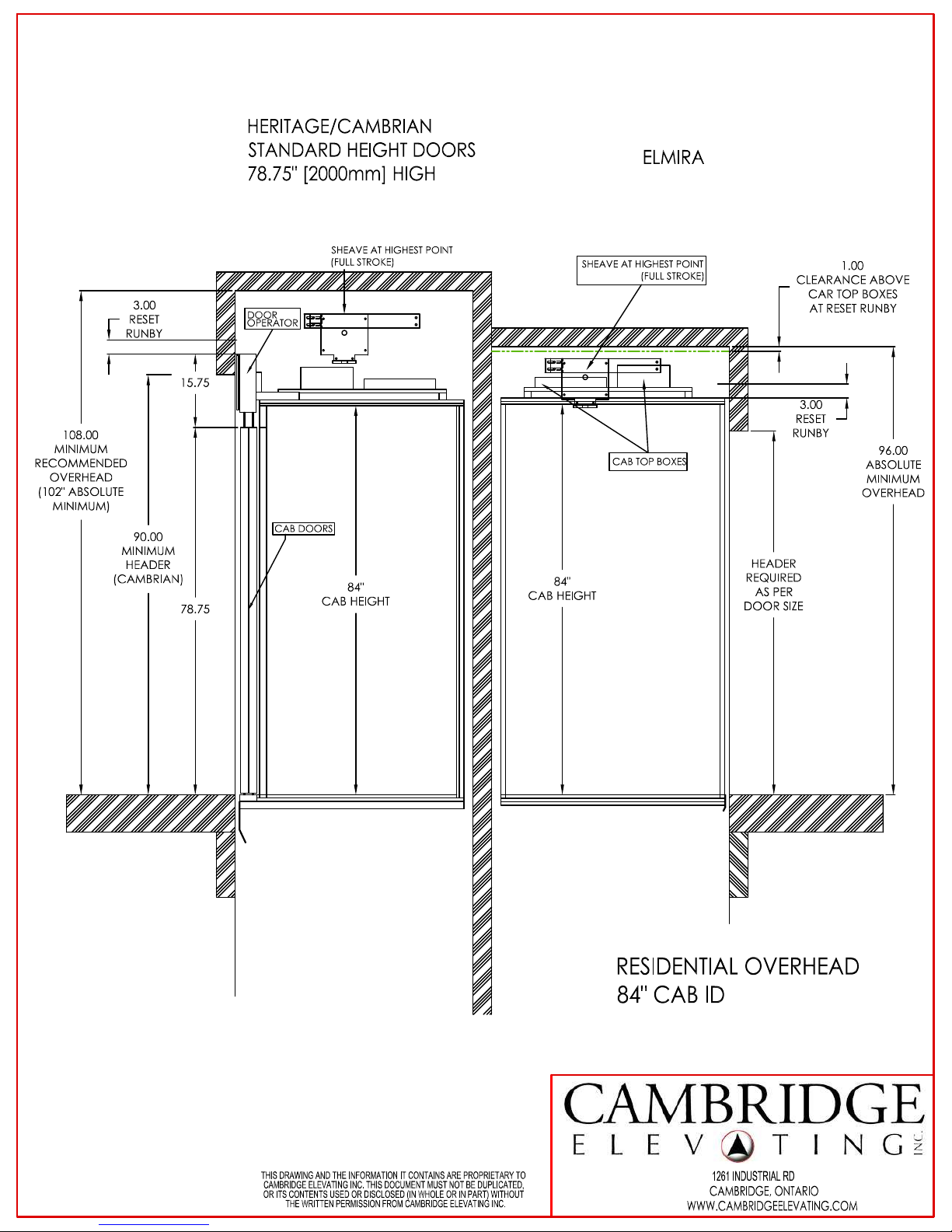
Elmira minimum pit depth: 8”
Elmira minimum overhead clearance: 96”
Heritage/Cambrian minimum pit depth: 12”
Heritage/Cambrian minimum overhead: 108”
Maximum travel: 50 feet
Maximum number of stops: 6
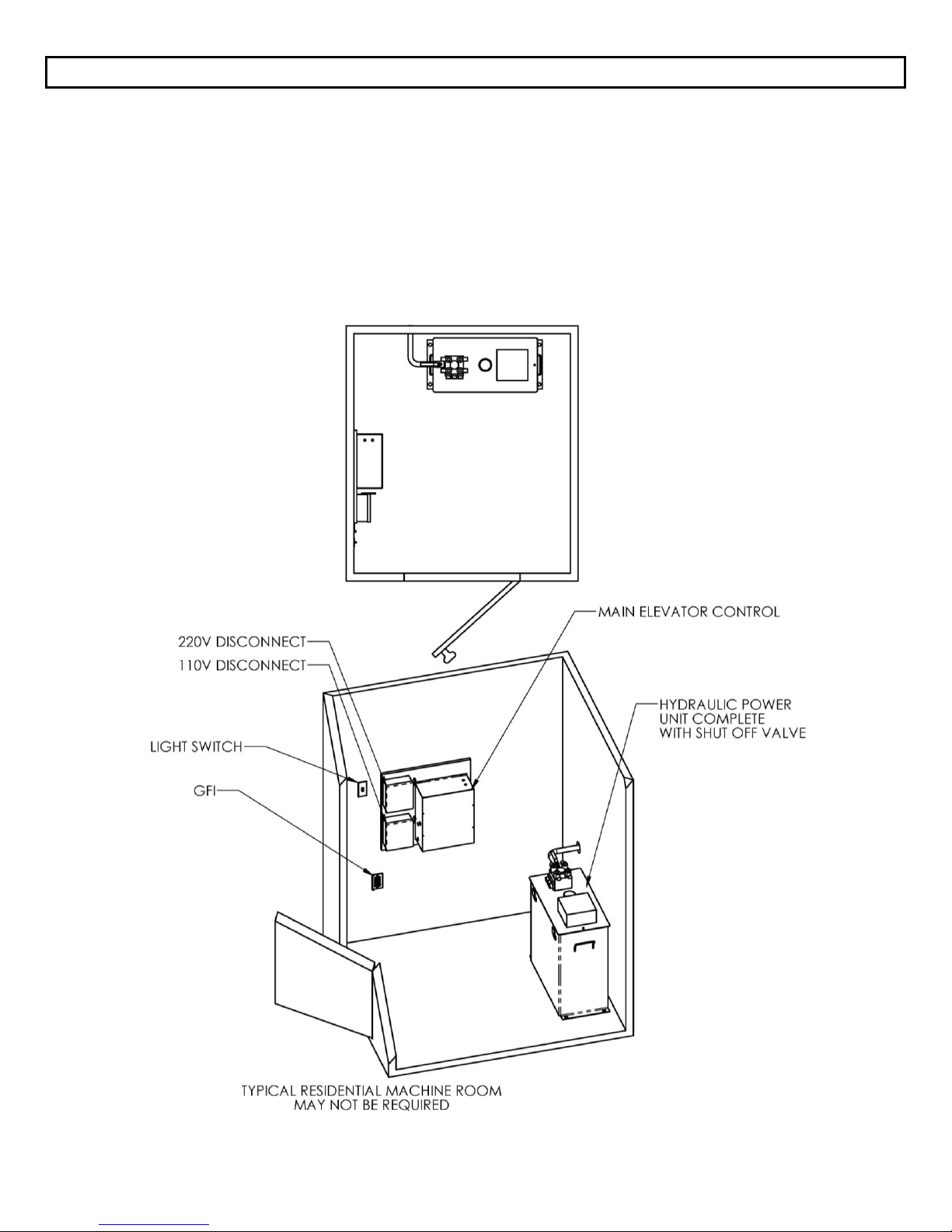
Mechanical Equipment
220 VAC, 60 Hz, 30 Amp single phase power
Dual 8 lb. modular T-rail system
Two 3/8” diameter, 17 x 9 wire ropes
Sling assembly
Forged rope sockets
2:1 roped hydraulic single stage cylinder
Submersed electric motor with 2-speed
adjustable valve system
Cab and Appointments
Car size: Up to 20 sq. ft. standard
Cab height: 84" standard, 96" & custom optional
Recessed LED cab lights – 2 or 4 lights depending
on cab size
Interior cab walls and ceiling finish, choice of:
Melamine: cherry, oak, maple, walnut, white, black
Veneer (unfinished) –birch, cherry, maple, oak,
walnut
(MDF) Medium density fibreboard – paint grade
Rough plywood cab floor with ¾” recess
Gates and Doors
Elmira
Swing door for each landing
Horizontally collapsible accordion style car gate(s)
Heritage
Swing door for each landing
Automatic sliding cab door panels (beige or s/s)
Cambrian
Automatic sliding cab door panels (beige or s/s)
Automatic sliding landing door panels (beige or s/s)
Controls
Microprocessor controller with relays for basic
operation
Fully automatic operation
Automatic timed cab lighting
Stainless steel car operating panel (COP),
telephone box and hall call stations
Dual illuminated hall call station push buttons
and position indicating push buttons on COP
Emergency stop switch on COP
LED/dot matrix Digital Position Indicator (DPI)
in car
Safety Devices
Stainless steel handrail inside cab
220 VAC lockable disconnect for power unit
Final limit switch
Slack rope safety switch
Pit stop switch
Car top stop switch
Line rupture valve
Low pressure switch
Automatic leveling (anti-creep)
Emergency battery lowering
Electro-mechanical door interlocks
Manual lowering device
Telephone in cab
Options
Custom cab sizes/heights. Oversized cabs
where permitted (variance may be required)
Unfinished oak, maple or cherry solid
hardwood / face frame hardwood cab walls and
ceiling
Stainless steel patterned cab walls and ceiling
Custom finish elevator fixtures (COP, telephone
box and hall call stations) in choice of plating
finishes: Brushed brass, oil rubbed bronze,
polished stainless, brushed nickel, consult
factory for additional choices.
Two piece hydraulic jack
Additional handrails in cab
Handrail COP (all models)
LED/dot matrix Digital Position Indicator (DPI)
hall call stations on landings
Veneer and decorative metal wrapped sliding
door panels (Heritage/Cambrian)

www.CambridgeElevating.com August 2017
6
Hoistway Construction – General Notes
A load-bearing wall is required to sustain rail reactions; please see Rail Wall Construction – Wood Stud
Wall (next page) for detail.
Hoistway must be in accordance with ASME A17.1/CSA B44-13, AND all local codes and regulations.
Pit floor construction must withstand a 5,500 lb. load.
Due to limited clearances, it is necessary that hoistway walls be square and plumb. Maximum
permissible deviation from hoistway top to bottom is 1/8”.
Building structure must sustain a chain hoist for hoisting elevator materials to the top of the hoistway
during installation.
A structural engineer must ensure that building and hoistway can safely support all loads imposed by
the elevator equipment.
The drawings contained herein have been prepared using engineering principles and the design
loads that are applied by the rails to the wall. However the details and member sizes and the
attachments to the structure should not be construed as a complete wall system. The contractor
and/or the project engineer are responsible to evaluate the other loads that are applied to the wall
from the floor or roof system and modify sizes or connections as required by their analysis.

ALL OTHER WALLS
AS PER LOCAL
BUILDING CODE
PIT
BOTTOM FLOOR
SLAB
RAIL WALL SHEATHING
3/4" PLYWOOD
SCREWED TO STUDS
EVERY 12"
WITH #10-2-1/2"
SCREWS MINIMUM
FOR BEST RESULTS
USE A CONSTRUCTION
ADHESIVE
IN ADDITION TO REQUIRED
WOOD SCREWS
SURFACE OF PLYWOOD
FLUSH
WITH WALL OF
PIT
WALLS WITH
DOOR
OPENINGS
MUST HAVE
2"X4" CONSTRUCTION
2"X4"
A
16 1
4
"
16 1
4
"
RAIL CENTERLINE
AS PER PROJECT
SHOP DRAWINGS
RAIL WALL CHANNEL
ASSEMBLY
TOP VIEW
- CHANNEL CONSTRUCTION TYPICAL
TWO PLACES
-
TWO 2" x 12" INSIDE TWO 2" x 6"
- 2x6s
SCREWED
TO 2x12s
EVERY
6"
WITH
#10x3-1/2" WOOD SCREWS
- CHANNELS AND MIDDLE STUDS
BETWEEN FLOORS
FULL HEIGHT OF
HOISTWAY
MIDDLE STUDS
THREE 2" x 6"
3/4"
PLYWOOD
DOOR
WALL
CAMBRIDGE ELEVATING IS NOT
RESPONSIBLE FOR THE STRUCTURAL
DESIGN OF THE BUILDING AND ITS
ABILITY TO SUPPORT THE ELEVATOR
LOADS AND/OR REACTIONS
R1=720LBS
R2=225LBS
R3=720LBS
WWW.CAMBRIDGEELEVATING.COM
CAMBRIDGE, ONTARIO
THIS DRAWING AND THE INFORMATION IT CONTAINS ARE PROPRIETARY TO
CAMBRIDGE ELEVATING INC. THIS DOCUMENT MUST NOT BE DUPLICATED,
OR ITS CONTENTS USED OR DISCLOSED (IN WHOLE OR IN PART) WITHOUT
THE WRITTEN PERMISSION FROM CAMBRIDGE ELEVATING INC.
1261 INDUSTRIAL RD


AS PER HOISTWAY LAYOUT
A A
PIT FLOOR TO BE DESIGNED FOR AN IMPACT LOAD OF 9600LBS
AND A STATIC LOAD OF 5500LBS UNDER CYLINDER
REINFORCING AND STRENGTH AS PER LOCAL
STANDARDS AND CODES
RESIDENTIAL PIT DETAILS
PIT FLOOR TO BE MADE OF
MINIMUM 15MPa CONCRETE
4.0
" MINIMUM
12"
FOR HERITAGE OR CAMBRIAN
8" MIN ELMIRA
SECTION A-A
FINISH BASEMENT
B
WWW.CAMBRIDGEELEVATING.COM
CAMBRIDGE, ONTARIO
THIS DRAWING AND THE INFORMATION IT CONTAINS ARE PROPRIETARY TO
CAMBRIDGE ELEVATING INC. THIS DOCUMENT MUST NOT BE DUPLICATED,
OR ITS CONTENTS USED OR DISCLOSED (IN WHOLE OR IN PART) WITHOUT
THE WRITTEN PERMISSION FROM CAMBRIDGE ELEVATING INC.
1261 INDUSTRIAL RD

www.CambridgeElevating.com August 2017
10
Machine Room Details – General Layout
Machine room must be in accordance with all codes and regulations.
A 220 VAC, 60 Hz, 30 Amp single phase power source in the machine room to be provided.
A 115 VAC, 60 Hz, 15 Amp single phase power source in the machine room to be provided.
A telephone line circuit to be provided if required. This circuit must be connected to an outside
line.

32"
26 1
4
"
26 1
4
"
29 3
4
"
14"
61
2
"
MIN CLEARANCE
10 1
4
"
28 1
4
"
12 3
4
"
TO BE LOCATED WITHIN 20ft OF
ELEVATOR HOISTWAY
FOR LONGER DISTANCES CONSULT
CAMBRIDGE ELEVATING
3.0 or 5.0 H.P. 220V/1/60Hz DRIVE MOTOR
ACCESS REQUIRED TO TOP OF UNIT
FOR OIL FILLING AND PIPING
DISCONNECTS SUPPLIED BY C.E.I. ON
MAIN ELEVATOR CONTROL PANEL
HYDRAULIC OIL:
32 WEIGHT PREMIUM
CAPACITY: 75L / 20 US Ga
HYDRAULIC LINE TO
CYLINDER
SHUT OFF
VALVE
FILLER BREATHER
FOR OIL
28"
30"
28
1
4
"
13"
PLYWOOD
MAIN ELEVATOR
CONTROLLER PANEL
LIGHTING
DISCONNECT
120VAC
15 AMP
NEMA 5-15P
PLUG
PUMP
DISCONNECT
240VAC
30 AMP
NEMA 14-30P
PLUG
8
1
2
"
HYDRAULIC
POWER UNIT
BES3 RESIDENTIAL PUMP
CONTROLLER DETAILS
WIRE GAUGE AS
PER LOCAL CODE
REQUIREMENTS
USUALLY MOUNTED IN
MECHANICAL ROOM
ON WALL
WITHIN 6' OF
HYDRAULIC POWER UNIT
OR TO STRUTS MOUNTED
ON REAR OF PUMP TANK
OUTLETS TO BE
SUPPLIED BY G.C
WITHIN 36"
OF THE
CONTROLLER ON THE
RIGHT SIDE.
REQUIRES:
*
NEMA 5-15
OUTLET AT 60" HIGH
*
NEMA 14-30
OUTLET AT 48" HIGH
WWW.CAMBRIDGEELEVATING.COM
CAMBRIDGE, ONTARIO
THIS DRAWING AND THE INFORMATION IT CONTAINS ARE PROPRIETARY TO
CAMBRIDGE ELEVATING INC. THIS DOCUMENT MUST NOT BE DUPLICATED,
OR ITS CONTENTS USED OR DISCLOSED (IN WHOLE OR IN PART) WITHOUT
THE WRITTEN PERMISSION FROM CAMBRIDGE ELEVATING INC.
1261 INDUSTRIAL RD

www.CambridgeElevating.com August 2017
12
Cambrian Landing Frame Details – Elevation
It is the recommendation of Cambridge Elevating to leave door walls wide open for installation.
Landing door jambs and header fit within rough stud opening. Landing door operating mechanism,
door frames and sill hang in hoistway attached to inside wall of hoistway using brackets.
Drawing below depicts view from landing looking into elevator hoistway (rails support on right wall).

www.CambridgeElevating.com August 2017
13
Cambrian Landing Frame Details – Layout
It is the recommendation of Cambridge Elevating to leave door walls wide open for installation.

www.CambridgeElevating.com August 2017
14
Elmira Model Cab / Hoistway Size Layout
Cab Size Centerlines Hoistway Size
Width x Depth
Landing
Door
Rail
Wall
36” x 48” 54” x 54.25” 31” 26.75”
36” x 54” 54” x 60.25” 31” 28.25”
36” x 60” 54” x 66.25” 31” 31.25”
40” x 48” 58” x 54.25” 35” 26.75”
40” x 54” 58” x 60.25” 35” 28.25”
Please note dimensions remain for mirrored configurations.
TYPE 1 – INLINE
Cab Size Centerlines Hoistway Size
Width x Depth
Landing
Door
Rail
Wall
36” x 48” 54” x 50.5” 31” 24.25”
36” x 54” 54” x 56.5” 31” 27.25”
36” x 60” 54” x 62.5” 31” 31.25”
40” x 48” 58” x 50.5” 35” 24.25”
40” x 54” 58” x 56.5” 35” 27.25”
Please note dimensions remain for mirrored configurations.
TYPE 2 – THROUGH

www.CambridgeElevating.com August 2017
15
Elmira Model Cab / Hoistway Size Layout
TYPE 3 or 4 (90-DEGREE) LH or RH
Cab Size Centerlines Hoistway Size
Width x Depth
Landing
Door
Rail
Wall
44” x 42” 54” x 56.25” 31” 27”
48” x 42” 58” x 56.25” 35” 29”
54” x 48” 64” x 62.25” 41” 32”
60” x 48” 70” x 62.25” 47” 35”
Please note dimensions remain for mirrored configurations.
TYPE 5 – INLINE
Cab Size Hoistway Size Centerlines
Width x Depth
Landing
Door
Rail
Wall
36” x 48” 51.75” x 54.25” 28.5” 25.25”
40” x 60” 55.75” x 66.25” 33” 31.25”
48” x 48” 63.75” x 54.25” 40.5” 25.25”
48” x 60” 63.75” x 66.25” 40.5” 31.25”
Please note dimensions remain for mirrored configurations.

www.CambridgeElevating.com August 2017
16
Heritage Model Cab / Hoistway Size Layout
Cab Size Hoistway Size Centerlines
Width x Depth
Landing
Door
Rail
Wall
44” x 48”
(2 panel doors) 62” x 57.75” 38.75” 27.75”
36” x 48”
(3 panel doors) 54” x 56.875” 32.75” 28.0625”
36” x 60”
(3 panel doors) 54” x 70.5” 32.75” 34.0625”
40” x 54”
(3 panel doors) 58” x 62.5” 34.75” 31.0625”
Please note dimensions remain for mirrored configurations.
TYPE 1 – INLINE
Cab Size Hoistway Size Centerlines
Width x Depth
Landing
Door
Rail
Wall
44” x 48”
(2 panel doors) 62” x 58.5” 38.75” 29.25”
36" x 48”
(3 panel doors) 54” x 59.75” 32.75” 29.875”
36" x 60”
(3 panel doors) 54” x 71.75” 32.75” 35.875”
40" x 54"
(3 panel doors) 58” x 65.75” 34.75” 32.875”
Please note dimensions remain for mirrored configurations.
TYPE 2 – THROUGH

www.CambridgeElevating.com August 2017
17
Cambrian Model Cab / Hoistway Size Layout
Cab Size Hoistway Size Centerlines
Width x Depth
Landing
Door
Rail
Wall
44” x 48”
(2 panel doors) 62” x 61.75” 38.75” 31.75”
36” x 48”
(3 panel doors) 54” x 63.25” 32.75” 33”
36” x 60”
(3 panel doors) 54” x 75.25” 32.75” 39”
40” x 54”
(3 panel doors) 58” x 69.25” 34.75” 36”
Please note dimensions remain for mirrored configurations.
TYPE 1 – INLINE
Cab Size Hoistway Size Centerlines
Width x Depth
Landing
Door
Rail
Wall
44” x 48”
(2 panel doors) 62” x 65.75” 38.75” 32.75”
36" x 48”
(3 panel doors) 54” x 68.5” 32.75” 34.25”
36" x 60”
(3 panel doors) 54” x 80.5” 32.75” 40.25”
40" x 54"
(3 panel doors) 58” x 74.5” 34.75” 37.25”
Please note dimensions remain for mirrored configurations.
TYPE 2 – THROUGH

www.CambridgeElevating.com August 2017
18
Cambridge Elevating Inc. Residential Elevator Specifications
PART 1 – GENERAL
1.1 Summary
This specification describes the planning, labor, and materials required to install a private residence home
elevator manufactured by Cambridge Elevating Inc.
1.2 System Description
A private residence 1:2 roped hydraulic elevator complete with guide rail system, hydraulic power unit,
control panel, switches, wiring and any parts necessary to properly install the elevator to meet
performance, safety and code standards.
1.3 Quality Assurance
The elevator shall be designed, tested and installed in compliance with all applicable regulations and in
accordance with ASME A17.1/CSA B44.0 standards. Elevator may be subject to state, local and city approval
prior to installation and subject to inspection after installation.
1.4 Applicable Codes and Standards
1.4.1 ASME A17.1/CSA B44-13, Section 5.3 Private Residence Elevators
1.4.2 ASME A17.5/CSA B44.1, Elevator and Escalator Electrical Equipment
1.4.3 ICC/ANSI A117.1-1998, Accessible and Usable Buildings and Facilities
1.4.4 NFPA 70-1999, National Electric Code
1.4.5 ADAAG, Americans with Disabilities Act Accessibility Guidelines
PART 2 – PREPARATORY WORK BY OTHERS
2.1 Hoistway
Provide an enclosed, plumb and square hoistway with smooth interior surfaces. Provide fascias or furring
of hoistway interior where required. Provide correct door RSO and headers as described on site specific
layout drawings. Construction of hoistway, including rail support wall and pit floor must withstand all loads
as described on site specific layout drawings. Rail wall construction must provide adequate anchoring
means for guide rail support system as described in hoistway detail drawings.
2.2 Machine Room
Provide a machine room as required by applicable codes and standards.
2.3 Electrical
2.3.1 General Contractor to provide one 220 VAC, 60 Hz, 30 Amp single phase power source in the machine
room. 230 VAC disconnect provided by Cambridge Elevating.
2.3.2 General Contractor to provide one 120VAC, 60 Hz, 15 Amp power source and disconnect in the
machine room. 120 VAC disconnect provided by Cambridge Elevating.

www.CambridgeElevating.com August 2017
19
PART 3 – SUBMITALS
3.1 Approval Drawings
Approval drawings shall show a complete layout of elevator equipment, including plan and elevation
views.
PART 4 – PRODUCT
4.1 Equipment Manufacturer
The elevator shall be manufactured by Cambridge Elevating Inc.
4.2 Components
The elevator will have the following components.
4.2.1 Cab
4.2.1.1 Car sizes (please visit our full drawings pages at (http://cambridgeelevating.com/tools)
Please refer to the Drawings pages for representative standard sizes. Custom cab sizes are available,
please consult your authorized dealer or CE sales representative.
** A minimum cab width of 44” is required for 2-speed/panel doors.
4.2.1.2 Cab Configuration
Inline (enter/exit same side), 90 degree or straight-thru layouts available.
4.2.1.3 Cab Construction
Metal bracket and/or tubular frame structure with melamine, veneer, stainless steel or laminate finish
panels. Ceiling white melamine or to match walls. Rough plywood floor is supplied - finish flooring by
others.
4.2.1.4 Car Operating Panel
A brushed stainless steel flush panel is built into the cab wall. Floor selection pushbuttons with a dual color
LED floor number and annular ring. Alarm button, emergency stop button, emergency light and integral
phone box with phone and hinged cover are included.

www.CambridgeElevating.com August 2017
20
4.2.1.5 Hand Rail
Brushed stainless steel handrail mounted to cab wall (shipped loose in unfinished cabs) in solid flat bar or
cylindrical. (Standard handrail is 36” x 1½” straight ends, flat)
4.2.2 Hydraulic Power Unit and Motor
Power unit to consist of 20 U.S. gallon enclosed metal tank, 4.0hp or 5.0hp submersible induction motor
and pump. Two-speed valve complete with adjustable leveling, pressure relief valve and shut off ball valve.
Pressure gauge, manual lowering valve and overheat thermistor included. Tank heater option is available.
4.2.3 Controller
Certified relay controller utilizing a Machine Control Unit (MCU) to manage the flow of signal information.
Battery back-up to allow lowering of car and unlocking and opening of doors during power outages.
4.2.4 Cylinder
Single stage jack with line rupture valve, 750 psi working pressure.
4.2.5 Ropes
Two 3/8” diameter, 9 x 17 wire ropes.
4.2.6 Guide rail
Dual 8 lb. steel modular T-rail system.
4.2.7 Car Sling
The elevator cab shall be supported by the car sling. The car sling shall be made of structural and formed
steel and equipped with guide rollers and Type "A" roller safeties complete with slack rope safety switch.
4.2.8 Gates and Doors
Landings: Automatic horizontally sliding two or three speed side opening beige epoxy or brushed stainless
door panels complete with matching frame and sill OR Manual swing door on landing provided by General
Contractor, the electromechanical door interlock can be provided by CEI (Automatic door operator
available).
Cab Door/Gate: Automatic horizontally sliding two or three speed side opening beige epoxy or brushed
stainless panels complete with sill OR horizontally sliding collapsible accordion style car gate (various
finishes available).
This manual suits for next models
2
Table of contents
Other Cambridge Elevating Elevator manuals