LIGHT PROGRESS FCU-CL [eng]
mag-2020 Pag. 6/20
fined inside the AHU ducts, allowing significant savings in operating costs and safeguarding people health from infec-
tious diseases such as:
1) Sick Building Syndrome, characterized by disturbances in the eyes and upper respiratory tracts (hyperactivity of
these mucous membranes) as well as nervous disorders (numbness, headache).
2) Legionellosis (Legionella Pneumophila - Legionnaires' typhoid). This pathology is frequently observed in environ-
ments with air conditioning systems. The Legionella infection can result in two distinct clinical pictures: Pontiac fever
and Legionnaires' disease. But it can also lead to the death of the infected person.
3) Tuberculosis (Mycobacterium Tub.) which is transmitted by air and enters the body through the respiratory route.
4) Humidifier disease or “Monday Fever”, characterized by an influenza-like symptoms that occur at the start-up of hu-
midification systems, and seem triggered by microorganisms able to proliferate in the ducts of air conditioning systems
during the weekend shutdown of air.
OPERATING
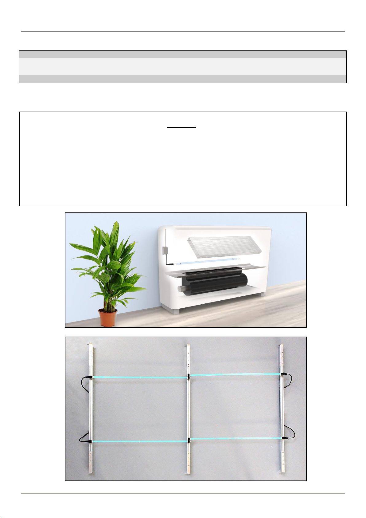
Air Sanitization in FANCOIL UNITS
UV-FCU-CL works with direct irradiation. With its action, you can obtain a strong microbial load reduction, both on air
and in all surfaces irradiated (Bacillus, Coli, Clostridium, Legionella, Vibrio, Salmonella, Pseudomonas, Staphylococ-
cus, Streptococcus, molds, virus, etc.). UV-FCU-CL disinfects the surface in the section between the fan and the heat
exchangers, radiating directly the air and removing all bacteria and viruses, such as influenza, that can be dragged by
bacteria itself, or by micro -airborne droplets.
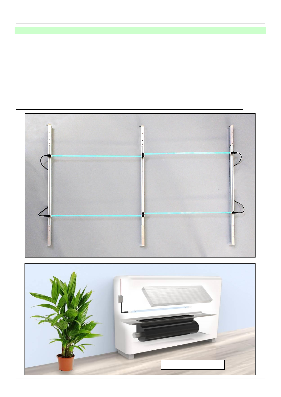
Air Sanitization in Air Handling Unit (AHU)
The device works by direct irradiation of UV-C rays. When the lampis turned on, it reduces the microbial load in the air
and on the surfaces enlightened by the UV lamp. For example, in 10÷15 seconds, at a distance of 20 cm from the de-
vice, you will achieve a 99% reduction of the bacteria Bacillus, Coli, Clostridium, Legionella, Vibrio, Salmonella, Pseu-
domonas, Staphylococcus, Streptococcus, etc. The use of this device is allowed only in absence of personnel inside
the AHU environment. In case of opening of a sector of the AHU, the switching-off of the lamps must be provided, to
avoid personnel’s affections at eyes (conjunctivitis) and skin (rash). The programming of the switching-on of the device
can be made using specially designed electronic control units (MASTER series), which, above all in case of installation
of various equipment, can manage various operations such as:
- Timing. It is possible to program the duration of irradiation using of a timer.
- Turning-off. A safety system switches off the lamps when people enter inside the AHU duct.
- Failure alarm. In case of failure of one or more lamps, it will trigger a warning light on the framework clean contact.
- Hour Counter. To control the duration of a lamp and substitute it at the end of its lifetime.