LightAlarms Tel: (888) 552-6467 Fax: (800) 316-4515 www.lightalarms.com 09/13 750.1683 Rev. B
ELF650P-All plastic remote heads
1/1
LightAlarms Tel: (888) 552-6467 Fax: (800) 316-4515 www.lightalarms.com 09/13 750.1683 Rev. B
1/1
EFL650P-All plastic Remote heads
Installation instructions
1. Turn off AC power.
2. Remove the lens.
3. Install the gasket (8) on the back plate.
4. Align and snap in place the lamp assemblies with "stopper" oriented per Figure 1.
Note: handle lamp assemblies by applying a pressure on either end of the support
as per Figure 1.
5. Connect the lamp wires to the emergency circuit using wire nuts. For double lamp
assembly fixtures, lamps should be connected in parallel, not in series. Refer to
lamp voltage indicated on the unit.
6. Fasten the back plate with 4 screws to either a nema 4X rated junction box or
directly to a recessed junction box making sure the unit is properly sealed all around
(gasket will not guarantee an adequate seal on all surfaces).
Important: the junction box must be circular and nema 4X rated for the unit to retain
a nema 4X rating.
7. Adjust the lamp assemblies:
- Rotation: hold the lamp assembly and turn it to either side.
- Tilting: hold the lamp assembly and tilt it up or down.
8. Secure the lens to the back plate with the screws provided.
Caution: Do not tighten screws more than necessary. They are to be tightened just
enough to start compressing the o-rings.
The screw covers can be installed to prevent the accumulation of debris on the
screws.
9. Turn on power and check the operation of your lighting fixture.
Lamps replacement
Refer to the relamping label located near the lamp holder or the recommended maximum
wattage. Do not exceed recommended wattage.
WARNING:
Risk of Shock.
Disconnect Power before Installation.
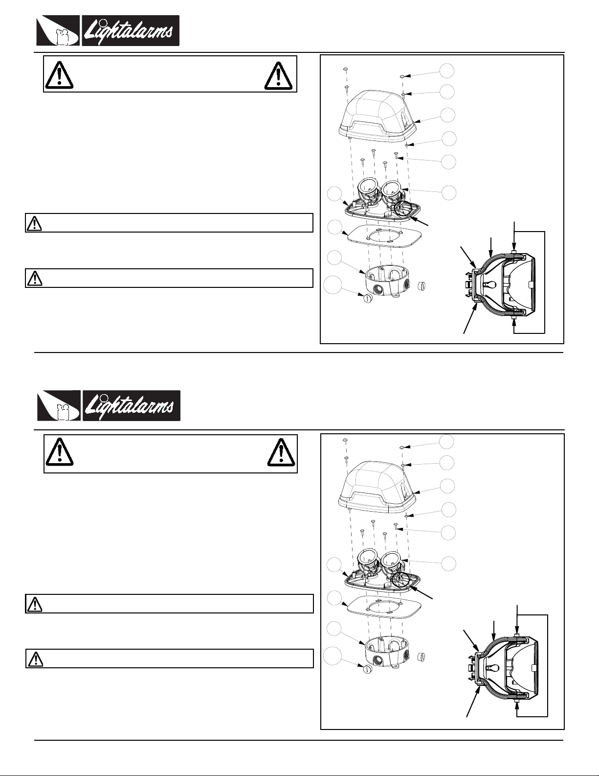
Parts List
1. Screw cover (2)
2. Lens screw (2)
3. Lens
4. O-ring (2)
5. Junction box screw (not
provided)
6. Lamp assembly (1 or 2)
7. Plastic back plate
8. Gasket
9. Weather proof junction
box (sold separatly under
Thomas&Betts P/N
E365D-CAR or E365DW-
CAR)
10. Plugs (sold separately
under Thomas&Betts P/N
P7701W-CAR)
Figure 1 Stopper
No stopper Support
Apply pressure here
when handling
Stopper
Installation instructions
1. Turn off AC power.
2. Remove the lens.
3. Install the gasket (8) on the back plate.
4. Align and snap in place the lamp assemblies with "stopper" oriented per Figure 1.
Note: handle lamp assemblies by applying a pressure on either end of the support
as per Figure 1.
5. Connect the lamp wires to the emergency circuit using wire nuts. For double lamp
assembly fixtures, lamps should be connected in parallel, not in series. Refer to
lamp voltage indicated on the unit.
6. Fasten the back plate with 4 screws to either a nema 4X rated junction box or
directly to a recessed junction box making sure the unit is properly sealed all around
(gasket will not guarantee an adequate seal on all surfaces).
Important: the junction box must be circular and nema 4X rated for the unit to retain
a nema 4X rating.
7. Adjust the lamp assemblies:
- Rotation: hold the lamp assembly and turn it to either side.
- Tilting: hold the lamp assembly and tilt it up or down.
8. Secure the lens to the back plate with the screws provided.
Caution: Do not tighten screws more than necessary. They are to be tightened just
enough to start compressing the o-rings.
The screw covers can be installed to prevent the accumulation of debris on the
screws.
9. Turn on power and check the operation of your lighting fixture.
Lamps replacement
Refer to the relamping label located near the lamp holder or the recommended maximum
wattage. Do not exceed recommended wattage.
WARNING:
Risk of Shock.
Disconnect Power before Installation.
Figure 1 Stopper
No stopper Support
Apply pressure here
when handling
Stopper
Parts List
1. Screw cover (2)
2. Lens screw (2)
3. Lens
4. O-ring (2)
5. Junction box screw (not
provided)
6. Lamp assembly (1 or 2)
7. Plastic back plate
8. Gasket
9. Weather proof junction
box (sold separatly under
Thomas&Betts P/N
E365D-CAR or E365DW-
CAR)
10. Plugs (sold separately
under Thomas&Betts P/N
P7701W-CAR)


