Lika SFAS1-01000-BA2 Series User manual

User's guide
SFAS1-01000
SFAS1-02000
Miniature absolute draw-wire encoder
•Absolute draw-wire encoder with SSI interface
•Robust and com act design
•Resolution from 0.1 mm to 0.012 mm
•Max. measuring length: 1000 mm or 2000 mm
•Cable and M12 connector out uts
Suitable for the following models:
•SFAS1-01000-BA2-...
•SFAS1-01000-GA2-...
•SFAS1-02000-BA2-...
•SFAS1-02000-GA2-...
General Contents
Preliminary information 5
Safety summary 6
Identification 8
Mechanical installation 9
Electrical connection 13
SSI interface 17
Smart encoders & actuators

This publication was produced by Lika Electronic s.r.l. 2023. All rights reserved. Tutti i diritti riservati. Alle Rechte vorbehalten. Todos los
derechos reservados. Tous droits réservés.
This docu ent and infor ation contained herein are the property of Lika Electronic s.r.l. and shall not be reproduced in whole or in
part without prior written approval of Lika Electronic s.r.l. Translation, reproduction and total or partial odification (photostat copies,
fil and icrofil included and any other eans) are forbidden without written authorisation of Lika Electronic s.r.l.
The infor ation herein is subject to change without notice and should not be construed as a co it ent by Lika Electronic s.r.l. Lika
Electronic s.r.l. reserves the right to ake all odifications at any o ents and without forewarning.
This anual is periodically reviewed and revised. As required we suggest checking if a new or updated edition of this docu ent is
available at Lika Electronic s.r.l.'s website. Lika Electronic s.r.l. assu es no responsibility for any errors or o issions in this docu ent.
Critical evaluation of this anual by the user is welco ed. Your co ents assist us in preparation of future docu entation, in order
to ake it as clear and co plete as possible. Please send an e- ail to the following address [email protected] for sub itting your
co ents, suggestions and criticis s.

Table of contents
User's guide............................................................................................................................................................................................1
Table of contents.............................................................................................................................................................................3
Ty ogra hic and iconogra hic conventions...................................................................................................................4
Preliminary information..............................................................................................................................................................5
1 Safety summary..................................................................................................................................... 6
1.1 Safety.............................................................................................................................................................................6
1.2 Electrical safety.........................................................................................................................................................6
1.3 Mechanical safety....................................................................................................................................................7
2 Identification......................................................................................................................................... 8
3 Mechanical installation....................................................................................................................... 9
3.1 Overall di ensions...................................................................................................................................................9
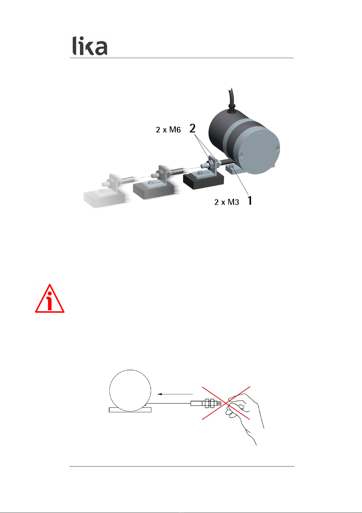
3.2 Mounting instructions.........................................................................................................................................10
3.3 Useful infor ation................................................................................................................................................11
3.4 Maintenance............................................................................................................................................................12
4 Electrical connection.......................................................................................................................... 13
4.1 Cable and connectors connections................................................................................................................13
4.2 M8 cable specifications.......................................................................................................................................13
4.3 M12 8-pin connector specifications.............................................................................................................14
4.4 Connection of the shield....................................................................................................................................14
4.5 Ground connection...............................................................................................................................................14
4.6 Zero setting input..................................................................................................................................................15
4.7 Counting direction input....................................................................................................................................16
5 SSI interface........................................................................................................................................ 17
5.1 SSI (Synchronous Serial Interface).................................................................................................................17
5.2 “LSB Right Aligned” protocol............................................................................................................................18
5.3 Reco ended trans ission rates.................................................................................................................21
5.4 Max. speed and counting frequency.............................................................................................................22
5.5 Reco ended SSI circuit..................................................................................................................................23

Ty ogra hic and iconogra hic conventions
In this guide, to ake it easier to understand and read the text the following typographic and
iconographic conventions are used:
•para eters are coloured in GREEN;
•alar s are coloured in RED;
•states are coloured in FUCSIA.
So e icons in the pages are expressly designed to highlight the parts of the text which are of great
interest and significance for the user. So eti es they are used to warn against dangers or potential
sources of danger arising fro the use of the device. You are advised to follow strictly the instructions
given in this guide in order to guarantee the safety of the user and ensure the perfor ance of the device.
In this guide the following sy bols are used:
This icon, followed by the word WARNING, is eant to highlight the parts of the
text where infor ation of great significance for the user can be found: user ust
pay the greatest attention to the ! Instructions ust be followed strictly in order
to guarantee the safety of the user and a correct use of the device. Failure to heed
a warning or co ply with instructions could lead to personal injury and/or da age
to the unit or other equip ent.
This icon, followed by the word NOTE, is eant to highlight the parts of the text
where i portant notes needful for a correct and reliable use of the device can be
found. User ust pay attention to the ! Failure to co ply with instructions could
cause the equip ent to be set wrongly: hence a faulty and i proper working of
the device could be the consequence.
This icon is eant to highlight the parts of the text where suggestions useful for
aking it easier to set the device and opti ize perfor ance and reliability can be
found. So eti es this sy bol is followed by the word EXAMPLE when instructions
for setting para eters are acco panied by exa ples to clarify the explanation.

Preliminary information
This guide is designed to provide the ost co plete and exhaustive infor ation the operator needs to
correctly and safely install and operate the SFAS1-01000 and SFAS1-02000 absolute draw-wire
encoders.
SFAS1-01000/SFAS1-02000 cable-pulling encoder is ai ed at speed and position easure ents and
controls in a variety of industrial applications through the ove ent of a 1,000 mm (39.37”) or 2,000
mm (78.74”) stainless steel wire. The typical back and forth travel of the oving equip ent causes the
wire to reel and unreel and thus the linear ove ent to be converted into a rotative otion detected by
the encoder which is coupled to the dru .
SFAS1-01000/SFAS1-02000 provides the absolute position infor ation through the “LSB Right Aligned”
protocol SSI interface.
To ake it easier to read and understand the text, this guide is divided into two ain sections.
In the first section so e general infor ation concerning the safety, the echanical installation and the
electrical connection as well as tips for setting up and running properly and efficiently the SFAS1-
01000/SFAS1-02000 cable-actuated encoder are provided.
In the second section, entitled SSI Interface, you can find detailed infor ation on the SSI interface.

SFAS1-01000 • SFAS1-02000
1 Safety summary
1.1 Safety
•Always adhere to the professional safety and accident prevention
regulations applicable to your country during device installation and
operation;
•installation and aintenance operations have to be carried out by
qualified personnel only, with power supply disconnected and stationary
echanical parts;
•device ust be used only for the purpose appropriate to its design: use for
purposes other than those for which it has been designed could result in
serious personal and/or the environ ent da age;
•high current, voltage and oving echanical parts can cause serious or
fatal injury;
•warning ! Do not use in explosive or fla able areas;
•failure to co ply with these precautions or with specific warnings
elsewhere in this anual violates safety standards of design, anufacture,
and intended use of the equip ent;
•Lika Electronic assu es no liability for the custo er's failure to co ply
with these require ents.
1.2 Electrical safety
•Turn OFF the power supply before connecting the device;
•connect according to the explanation in the ”Electrical connection” section
on page 13;
•connect Zero setting input to 0Vdc, if not used; to zero set the encoder,
connect Zero setting to +Vdc for 100 µs at least, then disconnect +Vdc;
nor ally voltage ust be at 0Vdc; zero set ust be perfor ed after
Counting direction; we suggest perfor ing the zero set when the encoder
is in stop;
•connect Counting direction input to 0Vdc, if not used; to have count up
infor ation when pulling the wire out = connect the input to 0Vdc; to
have count up infor ation when rewinding the wire = connect to +Vdc;
•in co pliance with 2014/30/EU nor on electro agnetic
co patibility, following precautions ust be taken:
-before handling and installing the equip ent, discharge
electrical charge fro your body and tools which ay co e in touch
with the device;
- power supply ust be stabilized without noise; install EMC filters on
device power supply if needed;
MAN SFAS1_01000_02000 SSI E 1.3 Safety su ary 6 of 24

SFAS1-01000 • SFAS1-02000
- always use shielded cables (twisted pair cables whenever possible);
- avoid cables runs longer than necessary;
- avoid running the signal cable near high voltage power cables;
- ount the device as far as possible fro any capacitive or inductive
noise source; shield the device fro noise source if needed;
- to guarantee a correct working of the device, avoid using strong agnets
on or near by the unit;
- ini ize noise by connecting the shield and/or the connector housing
and/or the fra e to ground. Make sure that ground is not affected by
noise. The connection point to ground can be situated both on the device
side and on user’s side. The best solution to ini ize the interference
ust be carried out by the user.
1.3 Mechanical safety
•Install the device following strictly the infor ation in the “Mechanical
installation” section on page 9;
•echanical installation has to be carried out with stationary echanical
parts;
•do not disasse ble the unit;
•do not tool the unit;
•delicate electronic equip ent: handle with care; do not subject the device
to knocks or shocks;
•respect the environ ental characteristics of the product;
•we suggest installing the unit providing protection eans against waste,
especially swarf as turnings, chips, or filings; should this not be possible,
please ake sure that adequate cleaning easures are in place in order to
prevent the wire fro ja ing;
•to avoid failures, never exceed the axi u easuring length and
prevent the wire fro tangling up;
•never release the wire freely, always help the wire wind properly: risk of
personal injury and/or equip ent da age;
•always keep the wire aligned not to da age the equip ent;
•the stroke per turn of the draw-wire unit is 100 (3.937”).
MAN SFAS1_01000_02000 SSI E 1.3 Safety su ary 7 of 24

SFAS1-01000 • SFAS1-02000
2 Identification
Device can be identified through the order code and the serial number printed
on the label applied to its body. Infor ation is listed in the delivery docu ent
too. Please always quote the order code and the serial nu ber when reaching
Lika Electronic. For any infor ation on the technical characteristics of the
product refer to the technical catalogue.
Warning: encoders having order code ending with "/Sxxx" ay have
echanical and electrical characteristics different fro standard and
be supplied with additional docu entation for special connections
(Technical Info).
MAN SFAS1_01000_02000 SSI E 1.3 Identification 8 of 24

SFAS1-01000 • SFAS1-02000
3 Mechanical installation
WARNING
Installation has to be carried out by qualified personnel only, with power supply
disconnected and echanical parts co pulsorily in stop.
3.1 Overall dimensions
Values are expressed in
MAN SFAS1_01000_02000 SSI E 1.3 Mechanical installation 9 of 24

SFAS1-01000 • SFAS1-02000
3.2 Mounting instructions
•Fasten the draw-wire unit onto a fixed support using two M3 screws 1;
•re ove the transport safety wire that pins the end of the easuring
wire;
•fix the end of the easuring wire to the oving ele ent using the
provided M6 nuts 2.
WARNING
We suggest installing the unit providing protection eans against waste,
especially swarf as turnings, chips, or filings; should this not be possible, please
ake sure that adequate cleaning easures are in place in order to prevent the
wire fro ja ing.
To avoid irreparable failures, never exceed the axi u easuring length and
prevent the wire fro tangling up.
Never release the wire freely, always help the wire wind properly: risk of personal
injury and/or equip ent da age.
MAN SFAS1_01000_02000 SSI E 1.3 Mechanical installation 10 of 24

SFAS1-01000 • SFAS1-02000
Always keep the wire aligned not to da age the equip ent ( axi u
deviation: 3°).
3.3 Useful information
If you want to know the maximum measuring length and the resolution of
the draw-wire encoder please refer to the order code. The stroke per turn is
always 100 (3.937”), the axi u nu ber of turns is 10 for SFAS1-01000
and 20 for SFAS1-02000.
EXAMPLE 1
SFAS1-01000-GA2-08192-RL010
Stroke per turn = 100 (3.937”)
Resolution per turn = 8,192 cpr
Max. nu ber of encoder revolutions = 4,096
Linear resolution = 0.012 = 12 µ
Infor ation per = 81.92
Max. nu ber of turns = 10
Max. easuring length = 1,000 (39.37”)
Nu ber of infor ation = 81,920
Interface = SSI “LSB Right Aligned”, Gray code
EXAMPLE 2
SFAS1-02000-BA2-04000-AM020
Stroke per turn = 100 (3.937”)
Resolution per turn = 4,000 cpr
Max. nu ber of encoder revolutions = 4,096
Linear resolution = 0.025 = 25 µ
Infor ation per = 40
Max. nu ber of turns = 20
MAN SFAS1_01000_02000 SSI E 1.3 Mechanical installation 11 of 24

SFAS1-01000 • SFAS1-02000
Max. easuring length = 2,000 (78.74”)
Nu ber of infor ation = 80,000
Interface = SSI “LSB Right Aligned”, Binary code
3.4 Maintenance
The easuring syste does not need any particular aintenance; anyway it has
to be handled with the ut ost care as any delicate electronic equip ent. Fro
ti e to ti e we reco end the following operations:
•the unit and the wire have to be cleaned regularly using a soft and clean
cloth to re ove dust, chips, oisture etc.; do not use oil to clean the
wire.
MAN SFAS1_01000_02000 SSI E 1.3 Mechanical installation 12 of 24

SFAS1-01000 • SFAS1-02000
4 Electrical connection
WARNING
Electrical connection ust be carried out by qualified personnel only, with
power supply disconnected and echanical parts co pulsorily in stop.
4.1 Cable and connectors connections
Function M12 8- in M8 cable
0Vdc 1 Black
+10Vdc +30Vdc 2 Red
Clock IN + 3 Yellow
Clock IN - 4 Blue
Data OUT + 5 Green
Data OUT - 6 Orange
Zero setting 7 White
Counting direction 8 Grey
Shielding Case Shield
4.2 M8 cable s ecifications
Model : LIKA HI-FLEX sensor cable type M8 cable
Cross section : 2 x 0.22 2 + 6 x 0.14 2 (24/26 AWG)
Jacket : PUR (ether base), halogen free, oil, hydrolysis, abrasion
resistant
Shield : tinned copper braid, coverage 85%
Outer dia eter : 5.5 ± 0.2 (0.216” ± 0.0079”)
Min. bending radius : Ø x 7.5
Work te perature : -40°C +90°C (-40°F +194°F) – dyna ic installation
-50°C +90°C (-58°F +194°F) - fixed installation
Conductor resistance : 84.7 /k / 152 /k
MAN SFAS1_01000_02000 SSI E 1.3 Electrical connection 13 of 24

SFAS1-01000 • SFAS1-02000
4.3 M12 8- in connector s ecifications
Male
Frontal side
A coding
4.4 Connection of the shield
For signals trans ission always use shielded cables. The cable shielding ust be
connected properly to the etal ring nut 3 of the connector in order to ensure
a good earthing through the fra e of the device. To do this disentangle and
shorten the shielding 1 and then bend it over the part 2; finally place the ring
nut 3 of the connector. Be sure that the shielding 1 is in tight contact with the
ring nut 3.
4.5 Ground connection
Mini ize noise by connecting the shield and/or the connector housing and/or
the fra e to ground. Make sure that ground is not affected by noise. The
connection point to ground can be situated both on the device side and on
user’s side. The best solution to ini ize the interference ust be carried out by
MAN SFAS1_01000_02000 SSI E 1.3 Electrical connection 14 of 24

SFAS1-01000 • SFAS1-02000
the user. You are advised to provide the ground connection as close as possible
to the encoder.
4.6 Zero setting in ut
The output value can be set to zero (reset) via an external signal issued by a PLC
or other controller device. When the internal icroprocessor receives the signal
it resets the output infor ation. This function can be very useful for setting the
zero position of both the encoder and the achine. To zero set the encoder,
connect Zero setting input to +Vdc for 100 µs at least, then disconnect +Vdc;
nor ally voltage ust be at 0Vdc; zero set ust be perfor ed after Counting
direction setting; we suggest perfor ing the zero set when the encoder is in
stop. Connect the Zero setting input to 0Vdc if not used.
NOTE
Please note that, after setting the zero point, the positive counting will be fro
0 towards the ax. value (see the table below); if you ove the axis before the 0
point, the detected value will be the ax. nu ber of infor ation – 1 down.
EXAMPLE
Let's suppose we are using the SFAS1-02000-xxx-08192-... odel; the encoder is
set to have the positive counting when pulling the cable out (see the Figure
below). If you set the 0 along the path, starting fro the 0 point, the output
values will be fro 0 towards the ax. value (163,840, see the table below)
when you pull out the cable; when the encoder oves back and cross the zero,
the value i ediately after 0 will be the ax. nu ber of infor ation – 1
(33,554,431).
... 33554430 33554431 0 1 2 ... 163840
MAN SFAS1_01000_02000 SSI E 1.3 Electrical connection 15 of 24

SFAS1-01000 • SFAS1-02000
Model Max. value Max. number of
information
SFAS1-01000-xxx-08192-... 81,920 25 bits (33,554,432)
SFAS1-02000-xxx-08192-... 163,840
SFAS1-01000-xxx-04000-... 40,000 25 bits (33,554,432)
SFAS1-02000-xxx-04000-... 80,000
SFAS1-01000-xxx-02000-... 20,000 25 bits (33,554,432)
SFAS1-02000-xxx-02000-... 40,000
SFAS1-01000-xxx-01000-... 10,000 25 bits (33,554,432)
SFAS1-02000-xxx-01000-... 20,000
4.7 Counting direction in ut
The counting direction circuit allows to reverse the counting direction. The
standard counting direction (count up infor ation) is to be intended when
pulling the wire out. This input allows the count up when rewinding the wire.
Connect the counting direction input to 0Vdc to have an increasing count when
pulling the wire out; connect the counting direction input to +Vdc to have an
increasing count when rewinding the wire. Connect the Counting direction
input to 0Vdc if not used.
WARNING
After having set the new counting direction it is necessary to zero set the
encoder position.
Positive counting direction (count u information) when ulling the wire
out
MAN SFAS1_01000_02000 SSI E 1.3 Electrical connection 16 of 24

SFAS1-01000 • SFAS1-02000
5 SSI interface
Order code: SFAS1-xxxxx-BA2-…
SFAS1-xxxxx-GA2-…
5.1 SSI (Synchronous Serial Interface)
SSI (the acrony for Synchronous Serial
Interface) is a synchronous point-to-point serial
interface engineered for unidirectional data
trans ission between one Master and one Slave.
Developed in the first eighties, it is based on the RS-
422 serial standard. Its ost peculiar feature is that data trans ission is
achieved by synchronizing both the Master and the Slave devices to a co on
clock signal generated by the controller; in this way the output infor ation is
clocked out at each controller's request. Further ore only two pairs of twisted
wires are used for data and clock signals, thus a six-wire cable is required.
The ain advantages in co parison with parallel or asynchronous data
trans issions are:
•less conductors are required for trans ission;
•less electronic co ponents;
•possibility of insulating the circuits galvanically by eans of
optocouplers;
•high data trans ission frequency;
•hardware interface independent fro the resolution of the absolute
encoder.
Further ore the differential trans ission increases the noise i unity and
decreases the noise e issions. It allows ultiplexing fro several encoders, thus
process controls are ore reliable with si plified line design and easier data
anage ent.
Data trans ission is carried out as follows.
At the first falling edge of the clock signal (1, the logic level changes fro high
to low) the absolute position value is stored while at the following rising edge
(2) the trans ission of data infor ation begins starting fro the MSB.
MAN SFAS1_01000_02000 SSI E 1.3 SSI interface 17 of 24

SFAS1-01000 • SFAS1-02000
At each change of the clock signal and at each subsequent rising edge (2) one
bit is clocked out at a ti e, up to LSB, so co pleting the data word
trans ission. The cycle ends at the last rising edge of the clock signal (3). This
eans that up to n + 1 rising edges of the clock signals are required for each
data word trans ission (where n is the bit resolution); for instance, a 13-bit
encoder needs 14 clock edges. If the nu ber of clocks is greater than the
nu ber of bits of the data word, then the syste will send a zero (low logic
level signal) at each additional clock, zeros will either lead (LSB ALIGNED
protocol) or follow (MSB ALIGNED protocol) or lead and/or follow (TREE FORMAT
protocol) the data word. After the period T onoflop ti e, having a typical
duration of 16 µsec, calculated fro the end of the clock signal trans ission,
the encoder is then ready for the next trans ission and therefore the data
signal is switched high.
The clock signal has a typical logic level of 5V, the sa e as the output signal
which has custo arily a logic level of 5V in co pliance with RS-422 standard.
The output code can be either Binary or Gray (see the order code).
5.2 “LSB Right Aligned” rotocol
“LSB Right Aligned” protocol allows to right align the bits, beginning fro MSB
( ost significant bit) to LSB (least significant bit); LSB is then sent at the last
clock cycle. If the nu ber of clock signals is higher than the data bits, then
unused bits are forced to logic level low (0) and lead the data word. This
protocol can be used in encoders having any resolution.
The word is 25-bit long, unused bits are set to 0 (zero).
MAN SFAS1_01000_02000 SSI E 1.3 SSI interface 18 of 24

SFAS1-01000 • SFAS1-02000
Thus it will be as follows:
Model Counts er
revolution
Information
er mm Resolution Length of
the word
Max.
number of
information
SFAS1-01000-xxx-08192-... 8,192 91.92 0.012 25 bits 25 bits
(33,554,432)
SFAS1-02000-xxx-08192-...
SFAS1-01000-xxx-04000-... 4,000 40 0.025 25 bits 25 bits
(33,554,432)
SFAS1-02000-xxx-04000-...
SFAS1-01000-xxx-02000-... 2,000 20 0.05 25 bits 25 bits
(33,554,432)
SFAS1-02000-xxx-02000-...
SFAS1-01000-xxx-01000-... 1,000 10 0.1 25 bits 25 bits
(33,554,432)
SFAS1-02000-xxx-01000-...
The output code can be GRAY or BINARY (see the order code).
The length of the easuring step is equal to the resolution.
Structure of the trans itted position value:
SFAS1-xxxxx-xxx-xxxxx bit 25 … 1
value MSB … LSB
WARNING
Please note that the position value issued by the encoder is expressed in pulses;
thus you have then to convert the nu ber of pulses into a linear easuring
unit.
To convert the position value into illi etres ( ) or icro etres (µ ) you
have to ultiply the nu ber of infor ation by the linear resolution of the
encoder expressed in illi etres or icro etres.
To know the linear resolution of the encoder please consider that the stroke
er turn is 100 mm.
The linear resolution results fro the following calculation:
Linear resolution = Stroke per turn
Resolution cpr
MAN SFAS1_01000_02000 SSI E 1.3 SSI interface 19 of 24

SFAS1-01000 • SFAS1-02000
Then if you want to know the linear position value you will need to ultiply the
trans itted position value by the linear resolution.
Linear osition value = trans itted position * linear resolution
NOTE
Please note that the encoder's linear resolution can be read also in the order
code next to the rotary resolution. Refer to the product datasheet.
EXAMPLE 1
Let's suppose that we are using the SFAS1-01000-BA2-01000-... draw-wire
encoder.
The resolution of the easuring device is 1,000 cpr (= 0.1 , see the order
code in the product datatsheet).
As stated, the linear resolution results fro the following calculation:
Linear resolution = Stroke per turn
Resolution cpr
Linear resolution = 100 = 0.1 = 1,000 µ
1,000
Let's say that the trans itted position value is 123.
Thus the linear position value will be as follows:
Linear osition value = trans itted position * linear resolution
Linear osition value = 123 * 0.1 = 12.3 = 12,300 µ
MAN SFAS1_01000_02000 SSI E 1.3 SSI interface 20 of 24
This manual suits for next models
3
Table of contents
Other Lika Recording Equipment manuals