manuals.online logo
Brands
  1. Home
  2. •
  3. Brands
  4. •
  5. Lillipad
  6. •
  7. Boating Equipment
  8. •
  9. Lillipad Revo User manual

Lillipad Revo User manual

INSTALLATION INSTRUCTIONS
FOR BOATS WITH CROSSMEMBERS
THAT ARE 9 ½ - 24” APART
1. Mark the location of all crossmembers with masking tape.
2. Using the specifications below, determine the appropriate mount
location for your ladder and handles and mark the positions.
MOUNTING OPTIONS & SPECIFICATIONS
a. Determine the best mounting position for your ladder
and handles. When space allows, LilliPad’s preference is
position “C” (pictured below). Position “C” provides
added stability making the ladder easier to climb and
opens the deck for entry onto the boat.
POSITION “C”
b. Mount brackets must be secured directly to the chassis by using the
supplied extension brackets to bridge
the boats crossmembers. The brackets
must be properly spaced to allow the
ladder to slide smoothly in and out of
the mount brackets.
c. The outer edge of the mount bracket should
be positioned to allow a 1/4 – 1/2” gap
between the folded ladder and the rub rail.
(Note the reveal on the brackets, if needed)
d. Handles must be properly spaced from the ladder and positioned to
ensure that a minimum of one screw on each side of the handle is
secured through a cross member.
(Minimum of 1 “X” & 1 “Y” per handle) If
this requirement can not be met,
proper spacing for handle backer plates
is needed.
X
X
X
X
Y
Y
Y
Y
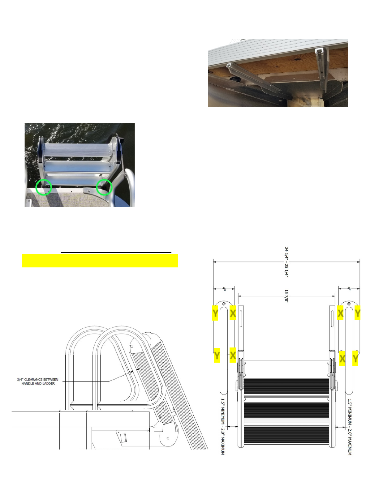
IMPORTANT: Now that you have determined the mounting position of your ladder
and handles you are ready to begin installation. If your boat has an underfloor skin
AND you are unable to secure the handles to a crossmember as outlined in
spcificiaiton “d” you must drop the underfloor skin and install your handles, first.
Once your handles are installed, reinstall the underloor skin and complete the
process to install your ladder, followed by installtion of the J-Snap Post.
LADDER INSTALLATION PROCEDURE
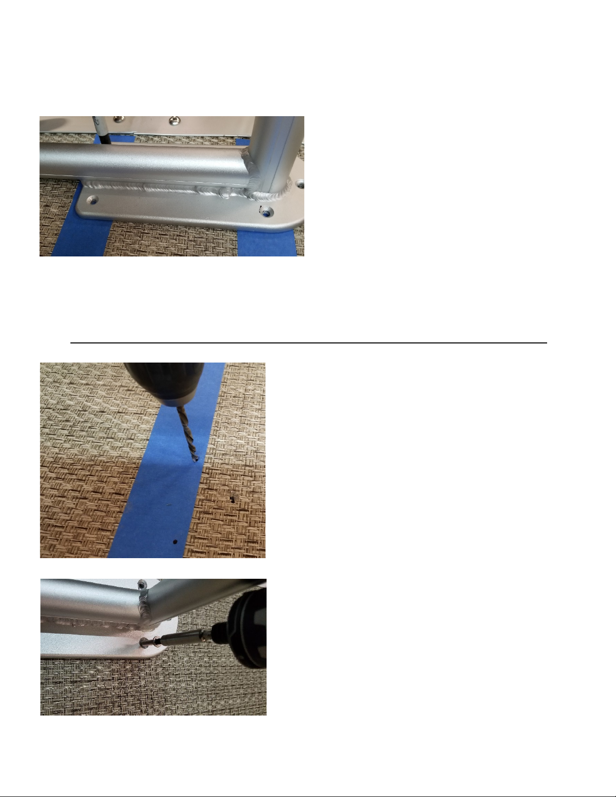
1. Secure the mount bracket to the
extension bracket, by installing a #14-1 ¼”
self-drilling screw through the slot in the
mount bracket into the pre-drilled hole in
the extension bracket. The mount bracket
should be secured to the extension with the
pin slot end flush or extended to meet the reveal noted in specification
“c”. Leave slightly loose for adjustment in a future step.
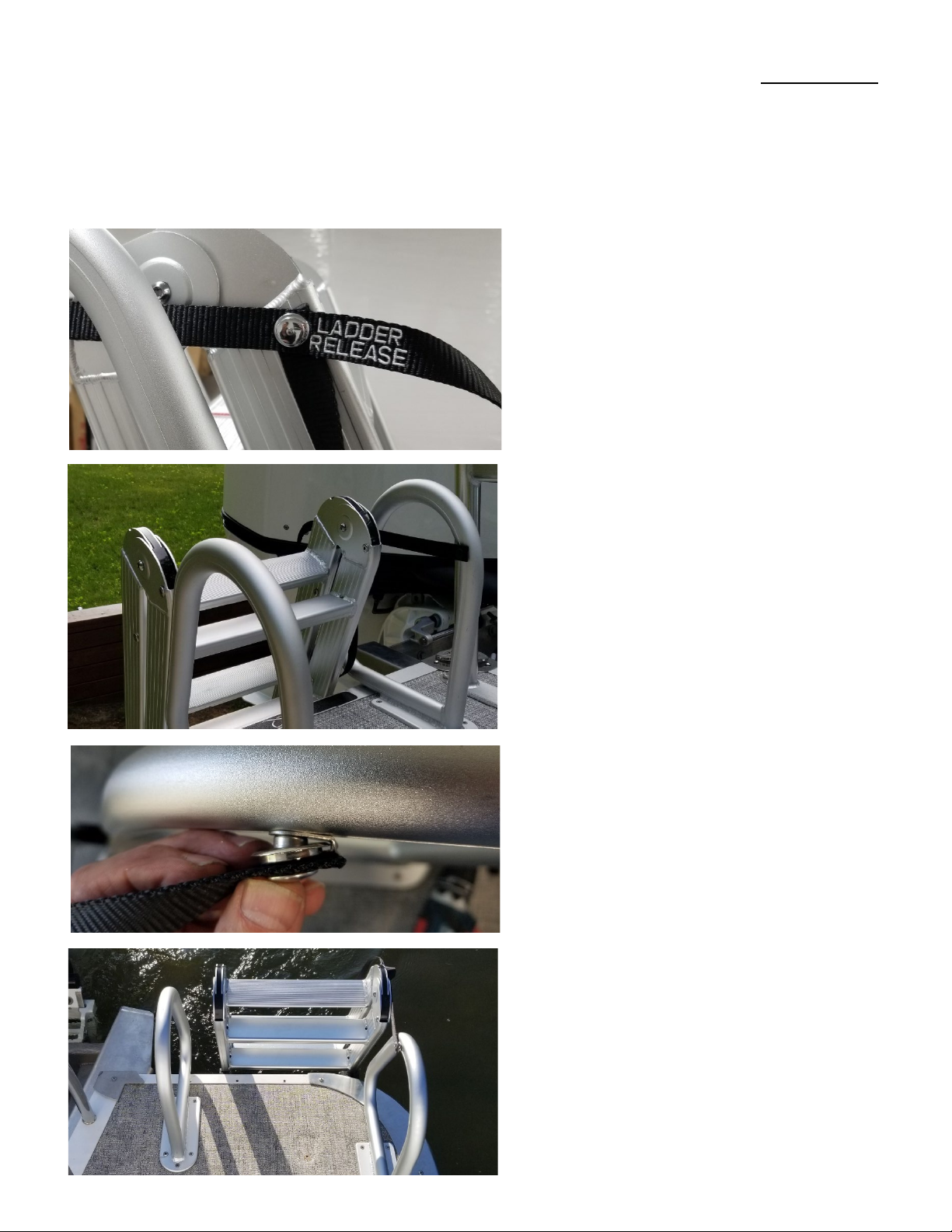
2. Put the bracket assemblies on the
ladder and pin them in place. (The end
of the bracket with the pin slot goes in
first to align with the retaining pin hole)
3. Hold the bracket assemblies to
the chassis and mark the
predetermined mount locations
on the cross members. (Confirm
your reveal from specification “c”.
Improper positioning will cause the
retracted ladder to hit the rub rail.)
4. Remove one bracket assembly from
the ladder.
5. Hold the loose bracket assembly in the
mounting location and mark the pre-
drilled hole location on the crossmember
closest to the rub rail.
6. Drill a 3/16” hole, in the crossmember,
in the noted location.
7. Install a #14 1 ¼” self-drilling screw.
Leave slightly loose for adjustment in
future step.
8. Using a square, confirm that your
bracket is squared in your mount
location.
9. Drill a 3/16” hole in the second slot line
as close to the center of the crossmember
as possible.
10. Install a #14 1 ¼” self-drilling screw.
Leave slightly loose for adjustment in
future step.
11. Slide the
ladder into the
installed mount
bracket and
confirm the mount location marks of the second bracket.
12. Remove the bracket from the ladder
and repeat steps 5 – 10 to complete
assembly of the second mount bracket.
13. Install the ladder
into the mount brackets
and adjust the position
of the brackets until the
ladder slides smoothly
in and out and then tighten the screws. (Do NOT over torque screws.)
14. To allow your ladder to slide easily, apply a small amount of
lubricant to the bracket.
HANDLE INSTALLATION PROCEDURE
REVO Ladder’s handles are designed to mount independently from the
ladder. Install handles to the following specifications:
a. Handles mounted to the side
of the ladder must have a
minimum of 1 ½” clearance
and a maximum of 2”
clearance between the ladder
and handle.
b. Handles must be positioned
to ensure that a minimum of
one screw on each side of the
handle is secured through a
cross member. (Minimum of 1
“X” & 1 “Y” per handle) or
backer plates
must be used.
c. Handles mounted
in front of the
folded ladder
must be spaced
with 3/4”
clearance.
1. Position handles in predetermined mount locations.
2. Mark all five screw locations for
each handle using a black marker.
3. Confirm that a minimum of one screw will be secured through a cross
member on each side of the handle. If this minimum requirement is not
met, the backer plates in your mount kit must be used for installation.
4. Drill 3/16” holes in each screw
location.
5. Place the handle in the mount location
and install #14-2” self-drilling screws.
(Do NOT over torque screws.)
If required, secure with the pre-drilled
backer plates using the included screws,
nuts and washers.
With the ladder and handles fully installed you must now install the J-Snap Post
which will secure the retracting/retaining strap to the handle. Proper placement
of the J-Snap Post is critical to ensuring the ladder is secured to the boat when in
the stowed position. Use the following procedure to properly install the J-Snap
Post:
1. Connect the Ladder Release
button to the post on the ladder.
This is a collet-style fastener that
is released by lifting the button.
To secure, simply push the
button onto the post.
2. With the ladder release
connected, pull the loose strap
back to the inside of the handle
to the point that it is snug but not
tight; mark the location on the
inside of the handle where the
snap meets.
3. Drill an 1/8” hole in the
location noted in step 2. Install
the J-Snap Post with the “hook”
of the post positioned to connect
at the END of the strap.
Proper positioning of the J-Hook
prevents the ladder from being
deployed unintentionally.
REVO Ladder Bow Mounts (sold separately) allow the ladder to be moved from
stern to bow. Install bow mount kits to the following specifications:
1. Install bow mounts on
the starboard side only.
2. The same installation
procedure should be
used to install the
mount brackets as
outlined above.
3. Bow mount kits utilize
just one handle which
must be installed on
the left side of the
ladder to allow the J-
Snap to be installed.
FOR INSTALLATION
QUESTIONS CONTACT:
LilliPad Marine
cschaub@lillipadmarine.com
800-279-3419

Popular Boating Equipment manuals by other brands

POWERWINCH Model 915 owner's manual

POWERWINCH

POWERWINCH Model 915 owner's manual

Hamilton Jet HTX30 product manual

Hamilton Jet

Hamilton Jet HTX30 product manual

Mercury BIGTILLER Operation manual

Mercury

Mercury BIGTILLER Operation manual

Seakeeper 5500 GYRO installation manual

Seakeeper

Seakeeper 5500 GYRO installation manual

Furuno FELCOM 250 Operator's manual

Furuno

Furuno FELCOM 250 Operator's manual

LENCO Auto Glide Installation & setup guide

LENCO

LENCO Auto Glide Installation & setup guide

Easytow ski owner's manual

Easytow

Easytow ski owner's manual

SureShade MTF Installation guides

SureShade

SureShade MTF Installation guides

EZ Dock Port MAX Series Owner's manual and installation instructions

EZ Dock

EZ Dock Port MAX Series Owner's manual and installation instructions

KARVER KMH2 user guide

KARVER

KARVER KMH2 user guide

Aerial FREERIDE BIMINI installation guide

Aerial

Aerial FREERIDE BIMINI installation guide

Lewmar FLUSH 2G Flush Hatch Fitting & Adjustment Instructions

Lewmar

Lewmar FLUSH 2G Flush Hatch Fitting & Adjustment Instructions

SKYLOTEC Jackpod Davit Instructions of use

SKYLOTEC

SKYLOTEC Jackpod Davit Instructions of use

South Pacific Industrial VS1500 Owner's installation & operations manual

South Pacific Industrial

South Pacific Industrial VS1500 Owner's installation & operations manual

Harken Performa 20.2 PTP Installation and maintenance manual

Harken

Harken Performa 20.2 PTP Installation and maintenance manual

Floe VSD 3800 Assembly instructions

Floe

Floe VSD 3800 Assembly instructions

ProFurl C290 installation manual

ProFurl

ProFurl C290 installation manual

Uflex PADDLE TRIM installation manual

Uflex

Uflex PADDLE TRIM installation manual

manuals.online logo
manuals.online logoBrands
  • About & Mission
  • Contact us
  • Privacy Policy
  • Terms and Conditions

Copyright 2025 Manuals.Online. All Rights Reserved.