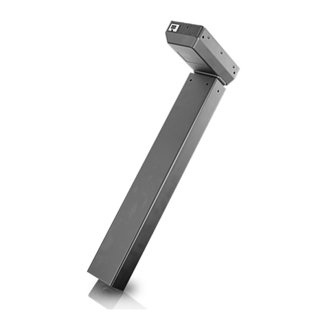
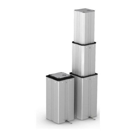
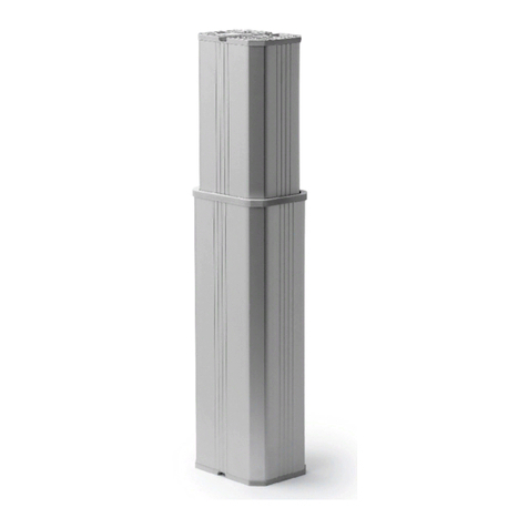
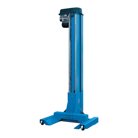
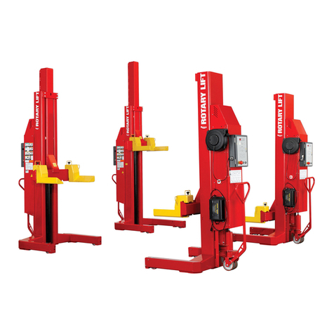
Linak TECHLINE ELEVATE - LC3 IC User manual

ELEVATE™ - LC3 IC
User Manual

Lifting Column LC3 IC | 2
Contents
Preface ������������������������������������������������������������������������������������������������������������������������������������������ 3
Terms of use ���������������������������������������������������������������������������������������������������������������������������������� 4
Safety information ������������������������������������������������������������������������������������������������������������������������� 5
Warnings ��������������������������������������������������������������������������������������������������������������������������������������� 5
Recommendations ������������������������������������������������������������������������������������������������������������������������� 6
Features and options���������������������������������������������������������������������������������������������������������������������� 7
Usage �������������������������������������������������������������������������������������������������������������������������������������������� 7
Speed, load and current curves ������������������������������������������������������������������������������������������������������ 8
Installation������������������������������������������������������������������������������������������������������������������������������������� 9
Built-in dimensions����������������������������������������������������������������������������������������������������������������������� 10
LC3 IC mounting guidelines��������������������������������������������������������������������������������������������������������� 10
Accessories ���������������������������������������������������������������������������������������������������������������������������������� 13
Electrical installation��������������������������������������������������������������������������������������������������������������������� 16
Connection diagram ELEVATE Easy����������������������������������������������������������������������������������������������� 17
I/O Specifications Elevate Easy������������������������������������������������������������������������������������������������������ 18
Connection diagram ELEVATE Pro ������������������������������������������������������������������������������������������������ 20
Connection diagram ELEVATE Pro ������������������������������������������������������������������������������������������������ 22
Connection diagram ELEVATE Modbus TCP/IP ������������������������������������������������������������������������������ 24
Mounting of tools on the side of an LC3 IC���������������������������������������������������������������������������������� 28
Maintenance ������������������������������������������������������������������������������������������������������������������������������� 29
Repair ������������������������������������������������������������������������������������������������������������������������������������� 29
Main groups of disposal ���������������������������������������������������������������������������������������������������������� 29
Warranty �������������������������������������������������������������������������������������������������������������������������������� 29
Declaration of conformity ����������������������������������������������������������������������������������������������������������� 30
DECLARATION OF INCORPORATION OF PARTLY
COMPLETED MACHINERY������������������������������������������������������������������������������������������������������������ 32

Lifting Column LC3 IC | 3
Preface
Dear User,
We are delighted that you have chosen a LINAK®product�
LINAK systems are high-tech products based on many years of experience in the manufacture and
development of actuators, electric control boxes, controls, batteries, accessories and chargers�
This User Manual does not address the end user� It is intended as a source of information for the equipment
or system manufacturer only, and it will tell you how to install, use and maintain your LINAK electronics�
The manufacturer of the end product has the responsibility to provide a User Manual, where relevant safety
information from this manual is passed on to the end user�
We are convinced that your LINAK product/system will give you many years of problem-free operation�
Before our products leave the factory, they undergo full function and quality testing� Should you,
nevertheless, experience problems with your product/system, you are always welcome to contact your
supplier�
LINAK subsidiaries and some distributors situated all over the world have authorised service centres, which
are always ready to help you� Locate your local contact information on the back page�
LINAK provides a warranty on all products� (See warranty section)�
This warranty, however, is subject to correct use in accordance with the specifications, maintenance being
done correctly, and any repairs being carried out at a service centre, which is authorised to repair LINAK
products�
Changes in installation and use of LINAK systems can affect their operation and durability� The products may
only be opened by authorised personnel�
This User Manual has been written based on the present technical knowledge� LINAK reserves the right to
carry out technical modifications and keeps the associated information updated�
LINAK A/S

Lifting Column LC3 IC | 4
Terms of use
LINAK®takes great care in providing accurate and up-to-date information on its products� However, the user
is responsible for determining the suitability of LINAK products for a specific application�
Due to continual development, LINAK products are subject to frequent modifications and changes� LINAK
reserves the rights to conduct modifications, updates, and changes without any prior notice� For the same
reason, LINAK cannot guarantee the correctness and actual status of imprinted information on its products�
LINAK uses its best efforts to fulfil orders� However, for the reasons mentioned above, LINAK cannot
guarantee availability of any particular product at any given time� LINAK reserves the right to discontinue the
sale of any product displayed on its website or listed in its catalogues or in other written material created
and produced by LINAK, LINAK subsidiaries, or LINAK affiliates�
All sales are subject to the ‘Standard Terms of Sale and Delivery for LINAK A/S’ available on LINAK websites�
LINAK and the LINAK logotype are registered trademarks of LINAK A/S� All rights reserved�

Lifting Column LC3 IC | 5
Safety information
Please read this safety information carefully:
Be aware of the following three symbols throughout the user manual:
Warning!
Failing to follow these instructions can cause accidents resulting in serious personal injury�
Recommendations
Failing to follow these instructions can result in the product suffering damage or being ruined�
Additional information
Usage tips or additional information that is important in connection with the use of the product�
Warnings
• Not to be used horizontal
• The product is NOT to be opened by unauthorised personel
• Always check correct assembly after mounting and service to ensure that the cable locks are
mounted
• Ensure that the cable cannot be squeezed, pulled or subjected to any other stress or damages
• LC3 IC is heavy (more than 20 kg)� To avoid personal injury and product damage, DO NOT DROP!
• Take special precautions concerning 3rd party interfacing� If needed, please contact LINAK for
further information
• Do not adjust anything during movement or while connected to mains, it can cause personal
injury�
• To avoid cable interruption and column defects make a proper cable installation and inspect
regularly for wear, damage and jarring sound� Defective parts must be replaced
•
After service inspection, the application must be tested for correct functionality before it is put
into operation� If used in parallel applications, misalignment between two or more columns must
be avoided
• Do not loosen any screws on the LC3 IC, this can cause collapse of the column!
• All cables must remain plugged in during cleaning to prevent the ingress of water�
•
The lifting column can become functional safety systems compliant with EN ISO10218-2�
To integrate the LC3 IC into a functional safety chain, external safety devices such as Safety
contactors/relays havs to be implemented

Lifting Column LC3 IC | 6
Recommendations
• Please follow the important LC3 IC mounting guidelines�
• LC3 IC is for use in both push and pull applications, cable outlet from smallest profile (top)�
See top and bottom plate dimensions� The Lifting Column can be mounted upside down�
• It is recommend to make a functional test of the application with all accessories connected before
putting it into operation
• Intended for indoor use only
• Not intended for use in harsh environments like e�g� pool environment, marine environment and
agriculture buildings with ammonia vapors
• Do not place the column in very dusty environments, since this effects the sliders
• Listen for unusual sounds and watch out for uneven running during operation� Stop the Lifting
column immediately if anything unusual is observed�

Lifting Column LC3 IC | 7
Features and options
Load in push and pull 1,000 N
Max speed 100 mm pr� second (adjustable and independent of load)
Stroke length In steps of 100 mm between 400 mm and 900 mm
Position accuracy +/- 1�5 mm
Profile colour Anodised aluminium
Top and bottom plate
colour
Zink grey bottom plate / aluminium grey top plate
Protection class IP44
Motor 24 V DC Brushless
Built-in dimensions Stroke/2 + 280 mm - minimum BID is 400/2 + 280 = 480 mm
Noise level 53 dB (A)
Weight 29 kg with 900 mm stroke
Dynamic bending
moment
Up to 1,400 Nm (allowed bending moment between cobot and column, while
the column is running in or out)
Static bending moment Up to 3,000 Nm (allowed bending moment between cobot and column, while
the column is not moving)
Mounting directions The column can be mounted vertically with a top plate upright or upside down
Cobot compatibility Mounting plates and URCap for Universal Robots e-Series / Mounting plates for
Doosan, Omron, Techman�
-For other options please contact TECHLINE®sales @ LINAK®A/S
IC interfaces: I/O
Modbus TCP/IP
Usage
Duty cycle 10 % at Full Load (2 minutes use, 18 minutes not in use)
20 % at Half load (4 minutes use, 16 minutes not in use)
Current consumption 6-20 A
Operation temperature +5 °C to + 40 °C
Storage temperature -40 °C to + 70 °C
Relative humidity 20 % to 80 % - non-condensing
Atmospheric pressure 700 to 1060 hPa
Meters above sea level Max� 3000 meters
Approvals EN 55016-2-3:2017+A1, EN 55016-2-1:2014
EN 61000-4-2:2009, EN IEC 61000-4-3:2020, EN 61000-4-4:2012
EN 61000-4-5:2014+A1, EN 61000-4-6:2014, EN 61000-4-8:2010
EN IEC 63000:2018
EN 61000-6-2:2019 – Part 6-2
EN 61000-6-4:2019 – Part 6-4
BS EN 55016-2-3:2017+A1, BS EN 55016-2-1:2014
BS EN 61000-4-2:2009, BS EN IEC 61000-4-3:2020, BS EN 61000-4-4:2012
BS EN 61000-4-5:2014+A1, BS EN 61000-4-6:2014, BS EN 61000-4-8:2010
BS EN IEC 63000:2018
BS EN 61000-6-2:2019 – Part 6-2
BS EN 61000-6-4:2019 – Part 6-4

Lifting Column LC3 IC | 8
Speed, load and current curves
0
100
120
140
160
0 200 400 600 800 1000 1200
Speed [mm/s]
Thrust [N]
LC3 IC 24V - speed vs thrust
20
40
60
80
0
3
6
9
12
15
18
21
24
0 250 500 750 1000
Current [A]
Load [N]
Minor side load during extention* High side load during extention**
LC3 IC 24V -current vs load
* The cobot and the load is positioned around the center of the column during extension�
** The cobot and load can be freely positioned placed or moved during extension�

Lifting Column LC3 IC | 9
Installation
Before mounting/dismounting the lifting column ensure that the following points are observed:
• The lifting column is not in operation�
• The lifting column is free from loads that could be released during this work�
Before the lifting column is been put into operation, check the following:
• The lifting column is correctly mounted as indicated in the relevant user instructions�
• The equipment can be freely moved over the lifting column’s whole working area�
• The lifting column is connected to a mains electricity supply/transformer with the correct voltage, and
which is dimensioned and adapted to the lifting column in question�
• Ensure that the voltage applied matches to the voltage specified on the lifting column label�
• Ensure that the connection screws are secured safely�

Lifting Column LC3 IC | 10
Built-in dimensions
A
A B
B
146 0.5
146 0.5
101 0.5
101 0.5
43 0.5
163 1
129 1
146 1
4315
M10x1.5
30
M10
30
REP = STANDARD-SBU
B-B
SECTION A-A
MIN.90MIN.60
(M8) 146
(M6) 144 -146
(M5) 143 -146
(M4) 142 -146
M8
Drill-Max. 16
Thread-Max 14
M6
Drill-Max. 15
Thread-Max 13
M5
Drill-Max. 13
Thread-Max 11
M4
Drill-Max. 12
Thread-Max 10
½ S + 280mm
Created By Pamir Hamid 2022-07-07
Modified By Pamir Hamid 2022-07-11
SCALE : 1:5
Drawing No.: TEC-0001888
SECTION C-C
C
C
M10x1.5 M10x1.5
The minimum built-in dimension (BID) is 480 mm due to the design of the lifting column�
The tolerance for BID is +/- 1�5 mm
LC3 IC mounting guidelines
LC3 IC is for use in push applications and can be mounted in both directions – largest profile down or
largest profile up� The column can only be used for vertical movement -not for horizontal�
Top plate up Top plate down
Note: The cable outlet for motor connection is positioned at the top (smallest profile)
Mount the LC3 IC in the application using the 4x M10 mounting holes in both endplates�
If the column is to be used with a constant high off-center load, we recommend to install the constant
weight in one of the 3 ways illustrated by the green symbols� It is not recommended to install the weight on
the opposite side of the mechanical endstop as illustrated with the red symbol� This installation can create an
uneven movement and noise when the lifting column reaches the endstop position�

Lifting Column LC3 IC | 11
Use 4 pcs� M10 8�8 bolts at each end of the column for mounting to the application�
The screw depth must be min� 20 mm and max� 30 mm in the aluminum profile�
Screw torque: 35 Nm�
A
A B
B
146 0.5
146 0.5
101 0.5
101 0.5
43 0.5
163 1
129 1
146 1
4315
M10x1.5
30
M10
30
REP = STANDARD-SBU
B-B
SECTION A-A
MIN.90MIN.60
(M8) 146
(M6) 144 -146
(M5) 143 -146
(M4) 142 -146
M8
Drill-Max. 16
Thread-Max 14
M6
Drill-Max. 15
Thread-Max 13
M5
Drill-Max. 13
Thread-Max 11
M4
Drill-Max. 12
Thread-Max 10
½ S + 280mm (HEAVY DUTY)
Created By Pamir Hamid 2022-07-07
Modified By Pamir Hamid 2022-07-11
SCALE : 1:5
Drawing No.: TEC-0001888
SECTION C-C
C
C
M10x1.5 M10x1.5
15 mm distance to thread Bolt depth min. 20 mm 43 mm distance to thread
Mounting holes
A
A B
B
146 0.5
146 0.5
101 0.5
101 0.5
43 0.5
163 1
129 1
146 1
4315
M10x1.5
30
M10
30
REP = STANDARD-SBU
B-B
SECTION A-A
MIN.90MIN.60
(M8) 146
(M6) 144 -146
(M5) 143 -146
(M4) 142 -146
M8
Drill-Max. 16
Thread-Max 14
M6
Drill-Max. 15
Thread-Max 13
M5
Drill-Max. 13
Thread-Max 11
M4
Drill-Max. 12
Thread-Max 10
½ S + 280mm
Created By Pamir Hamid 2022-07-07
Modified By Pamir Hamid 2022-07-11
SCALE : 1:5
Drawing No.: TEC-0001888
SECTION C-C
C
C
M10x1.5 M10x1.5
• It is recommended to use bolts with thread-lock adhesive
• Bolts of high quality steel 8�8 or 10�9 must be used to secure safe mounting of the LC3 IC to the
application�

Lifting Column LC3 IC | 12
Use 4 pcs� M10 8�8 bolts at each end of the column for mounting to the application�
The screw depth must be min� 20 mm and max� 30 mm in the aluminum profile�
Screw torque: 35 Nm�
A
A B
B
146 0.5
146 0.5
101 0.5
101 0.5
43 0.5
163 1
129 1
146 1
4315
M10x1.5
30
M10
30
REP = STANDARD-SBU
B-B
SECTION A-A
MIN.90MIN.60
(M8) 146
(M6) 144 -146
(M5) 143 -146
(M4) 142 -146
M8
Drill-Max. 16
Thread-Max 14
M6
Drill-Max. 15
Thread-Max 13
M5
Drill-Max. 13
Thread-Max 11
M4
Drill-Max. 12
Thread-Max 10
½ S + 280mm (HEAVY DUTY)
Created By Pamir Hamid 2022-07-07
Modified By Pamir Hamid 2022-07-11
SCALE : 1:5
Drawing No.: TEC-0001888
SECTION C-C
C
C
M10x1.5 M10x1.5
15 mm distance to thread Bolt depth min. 20 mm 43 mm distance to thread
Mounting holes
A
A B
B
146 0.5
146 0.5
101 0.5
101 0.5
43 0.5
163 1
129 1
146 1
4315
M10x1.5
30
M10
30
REP = STANDARD-SBU
B-B
SECTION A-A
MIN.90MIN.60
(M8) 146
(M6) 144 -146
(M5) 143 -146
(M4) 142 -146
M8
Drill-Max. 16
Thread-Max 14
M6
Drill-Max. 15
Thread-Max 13
M5
Drill-Max. 13
Thread-Max 11
M4
Drill-Max. 12
Thread-Max 10
½ S + 280mm
Created By Pamir Hamid 2022-07-07
Modified By Pamir Hamid 2022-07-11
SCALE : 1:5
Drawing No.: TEC-0001888
SECTION C-C
C
C
M10x1.5 M10x1.5
A
A B
B
146 0.5
146 0.5
101 0.5
101 0.5
43 0.5
163 1
129 1
146 1
4315
M10x1.5
30
M10
30
REP = STANDARD-SBU
B-B
SECTION A-A
MIN.90MIN.60
(M8) 146
(M6) 144 -146
(M5) 143 -146
(M4) 142 -146
M8
Drill-Max. 16
Thread-Max 14
M6
Drill-Max. 15
Thread-Max 13
M5
Drill-Max. 13
Thread-Max 11
M4
Drill-Max. 12
Thread-Max 10
½ S + 280mm
Created By Pamir Hamid 2022-07-07
Modified By Pamir Hamid 2022-07-11
SCALE : 1:5
Drawing No.: TEC-0001888
SECTION C-C
C
C
M10x1.5 M10x1.5
• It is recommended to use bolts with thread-lock adhesive
• Bolts of high quality steel 8�8 or 10�9 must be used to secure safe mounting of the LC3 IC to the
application�

Lifting Column LC3 IC | 13
Accessories
ELEVATE
ELEVATE is the cobot application for LC3 IC� It comes with different accessory options�
UR top mounting plate Bottom mounting plate
A
B
C
D
1 2 3 4 5 6
E
F
7 8
1 2 3 4
A
B
C
D
E
General Surface Character:
Name:
Updated:
Producer:
General Tolerance:
Material:
Type:
No.:
Created by:
Approved by:
Modified by:
Product:
Color:
No. Of check dimensions (#):
Format: Sheet: Scale: Volume:
Confidential: Property of LINAK A/S GROUP HEADQUARTER, DK-6430 NORDBORG, DENMARK Phone +45 73 15 15 15 ; FAX +45 74 45 80 48. Not to be handed over to, copied or used by third party.
WE IMPROVE YOUR LIFE
2D State:
3D State:
1002W1388-ATop Plate URLC3
Design/Iteration 7
Ra 3.2 µm
Design/Iteration 8
DIN ISO 2768-mK
-581252 mm³3:101/1A3
2022-09-05
-
Jesper HelbigNature
Jens Reuss Kristesen
EN AW 6082 -T6
-Aluminium
NB!
All other dimensions
according to 3D model.
A
B
C
D
1 2 3 4 5 6
E
F
7 8
1 2 3 4
A
B
C
D
E
General Surface Character:
Name:
Updated:
Producer:
General Tolerance:
Material:
Type:
No.:
Created by:
Approved by:
Modified by:
Product:
Color:
No. Of check dimensions (#):
Format: Sheet: Scale: Volume:
Confidential: Property of LINAK A/S GROUP HEADQUARTER, DK-6430 NORDBORG, DENMARK Phone +45 73 15 15 15 ; FAX +45 74 45 80 48. Not to be handed over to, copied or used by third party.
WE IMPROVE YOUR LIFE
2D State:
3D State:
1002W1387-ABottom Plate ElevateLC3
Design/Iteration 18
Ra 3.2 µm
Design/Iteration 9
DIN ISO 2768-mK
-386089 mm³3:101/1A3
2022-09-05
-
Jesper HelbigNature
Jens Reuss Kristesen
CK45
-Steel
NB!
All other dimensions
according to 3D model.
A
B
C
D
1 2 3 4 5 6
E
F
7 8
1 2 3 4
A
B
C
D
E
General Surface Character:
Name:
Updated:
Producer:
General Tolerance:
Material:
Type:
No.:
Created by:
Approved by:
Modified by:
Product:
Color:
No. Of check dimensions (#):
Format: Sheet: Scale: Volume:
Confidential: Property of LINAK A/S GROUP HEADQUARTER, DK-6430 NORDBORG, DENMARK Phone +45 73 15 15 15 ; FAX +45 74 45 80 48. Not to be handed over to, copied or used by third party.
WE IMPROVE YOUR LIFE
2D State:
3D State:
1002W1388-ATop Plate URLC3
Design/Iteration 7
Ra 3.2 µm
Design/Iteration 8
DIN ISO 2768-mK
-581252 mm³3:101/1A3
2022-06-20-
Jesper HelbigNature
Pamir HamidEN AW 6082 -T6
-Aluminium
NB!
All other dimensions
according to 3D model.
A
B
C
D
1 2 3 4 5 6
E
F
7 8
1 2 3 4
A
B
C
D
E
General Surface Character:
Name:
Updated:
Producer:
General Tolerance:
Material:
Type:
No.:
Created by:
Approved by:
Modified by:
Product:
Color:
No. Of check dimensions (#):
Format: Sheet: Scale: Volume:
Confidential: Property of LINAK A/S GROUP HEADQUARTER, DK-6430 NORDBORG, DENMARK Phone +45 73 15 15 15 ; FAX +45 74 45 80 48. Not to be handed over to, copied or used by third party.
WE IMPROVE YOUR LIFE
2D State:
3D State:
1002W1387-ABottom Plate ElevateLC3
Design/Iteration 18
Ra 3.2 µm
Design/Iteration 9
DIN ISO 2768-mK
-386089 mm³3:101/1A3
2022-06-02-
Jesper HelbigNature
Pamir HamidCK45
-Steel
NB!
All other dimensions
according to 3D model.

Lifting Column LC3 IC | 14
Doosan top mounting plate
A
B
C
D
1 2 3 4 5 6
E
F
7 8
1 2 3 4
A
B
C
D
E
General Surface Character:
Name:
Updated:
Producer:
General Tolerance:
Material:
Type:
No.:
Created by:
Approved by:
Modified by:
Product:
Color:
No. Of check dimensions (#):
Format: Sheet: Scale: Volume:
Confidential: Property of LINAK A/S GROUP HEADQUARTER, DK-6430 NORDBORG, DENMARK Phone +45 73 15 15 15 ; FAX +45 74 45 80 48. Not to be handed over to, copied or used by third party.
WE IMPROVE YOUR LIFE
2D State:
3D State:
1002W1389-ATop Plate Doosan TMLC3
Design/Iteration 7
Ra 3.2 µm
Design/Iteration 10
DIN ISO 2768-mK
-746189 mm³3:101/1A3
2022-09-05
-
Jesper HelbigNature
Jens Reuss Kristesen
EN AW 6082-T6
-Aluminium
NB!
All other dimensions
according to 3D model.
A
B
C
D
1 2 3 4 5 6
E
F
7 8
1 2 3 4
A
B
C
D
E
General Surface Character:
Name:
Updated:
Producer:
General Tolerance:
Material:
Type:
No.:
Created by:
Approved by:
Modified by:
Product:
Color:
No. Of check dimensions (#):
Format: Sheet: Scale: Volume:
Confidential: Property of LINAK A/S GROUP HEADQUARTER, DK-6430 NORDBORG, DENMARK Phone +45 73 15 15 15 ; FAX +45 74 45 80 48. Not to be handed over to, copied or used by third party.
WE IMPROVE YOUR LIFE
2D State:
3D State:
1002W1389-ATop Plate Doosan TMLC3
Design/Iteration 7
Ra 3.2 µm
Design/Iteration 10
DIN ISO 2768-mK
-746189 mm³3:101/1A3
2022-09-05
-
Jesper HelbigNature
Jens Reuss Kristesen
EN AW 6082-T6
-Aluminium
NB!
All other dimensions
according to 3D model.

Lifting Column LC3 IC | 15
Accessories
LC3 IC comes along with accessory kits to make the integration easy� The kits focus on cobot applications�
Article Number Description Content
1002W8163
All you need to get started with a
Universal Robot cobot� The mounting
plate works with UR3e, UR5e, UR10e,
UR16e� The ELEVATE URCap can be
downloaded from LINAK�com
ELEVATE Kit UR includes:
- Power cable, 2-pole, 5m (CAB0367046-5000)
- Signal cable, 9-pole, 5m (CAB0368539-5000)
- Cable relief + screw
- UR mounting plate with 4 screws M10 x 80mm 8�8
- Base mounting plate with 4 screws M10 x 40mm 8�8
1002W8164
All you need to get started with other
cobots: The mounting plate works with:
Doosan H-, M- and A-Series
Omron/TM: TM12 and TM14
ELEVATE Kit Doosan / Omron / TM includes:
- Power cable, 2-pole, 5m (CAB0367046-5000)
- Signal cable, 9-pole, 5m(CAB0368539-5000)
- Cable relief + screw
- Doosan/ Omron/ TM mounting plate
with 4 pcs� M10 x 80mm 8�8
- Base mounting plate with 4 pcs� M10 x 40mm 8�8
1002W8165
Cable Kit includes:
- Power cable, 2-pole, 5m (CAB0367046-5000)
- Signal cable, 9-pole, 5m (CAB0368539-5000)
- Cable relief + screw
The internal bending radius of the cables must be bigger than 3 times the outer dimension of the cable�
For instance if the outer cable dimension is Ø7, the internal radius of the maximum cable bending is 21 mm�

Lifting Column LC3 IC | 16
Electrical installation
When using soft stop on a DC motor, a short peak of high voltage will be sent back towards the power
supply� When selecting the power supply, it is important to ensure that is does not turn off the output,
when this backwards load dump occurs�
Depending of option there can be three different connectors on the LC3 IC Lifting Column:
• The most left is the power connector for a 24 V DC power supply, a cab0367046-xxxx cable fits the
connector
• In the middle there is a 9-pin signal connetor for controlling the LC3 IC and gathering information
regarding position and end stop signals� The cab0368543-xxxx cable that fits the connector should be
connected to a PLC or cobot controller�
• The connector to the most right is a RJ-45 for Modbus TCP/IP, a shielded (STP) cat 6 ethernet cable or a
cable with a category according to the requried transmission speed can be used with this connector�
The ethernet cable is not supplied by LINAK
The signal connector offers access to Actuator Connect�

Lifting Column LC3 IC | 17
Connection diagram ELEVATE Easy
LC3 XXX XXX F600 00 XXXX 6 2 3 1 4 - 1 F 0 (ELEVATE Easy)
BROWN
BLUE
GREEN
YELLOW
BLACK
RED
INWARDS
OUTWARDS
24V DC
INPUT/OUTPUT
M
Please be aware that if the power supply is not properly connected, you might damage the column!
Power Cable Signal Cable
Flying Leads Flying Leads
(Molex mini-fit 12-pin)

Lifting Column LC3 IC | 18
I/O Specifications Elevate Easy
Input/Output Specification Comments
Description Easy to use interface with integrated
power electronics (H-bridge)�
M
H-Bridge
Brown 24 VDC + (VCC)
Connect Brown to positive
24 V ± 10 %
24 V, max� 20 A - current cut off @20 A
Note:
Do not change the power supply polarity
on the brown and blue wires!
Power supply GND (-) is electrically
connected to the housing
Blue 24 VDC - (GND)
Connect Blue to negative
Red Extends the column The signal becomes active at:
> 67% of VIN
The signal becomes inactive at:
< 33% of VIN
Input current: 10 mA
The column comes with a 1500 ms soft
stop and start
Black Retracts the column
Yellow Endstop signal In Output voltage min� VIN - 2 V
Source current max� 100 mA
Endstop signals are NOT potential free�
Endstop positions can be configured
to any needed position with Actuator
Connect(R)� See virtual endstop�
Green Endstop signal Out
Current cut-offs should not be used as stop function! This might damage the column�
Current cut-offs should only be used in emergencies!
Current cut-off limits are not proportional with the load curves of the column� This means that the
current cut-offs cannot be used as load indicator�
There are tolerances on the spindle, nut, gear wheels etc� and these tolerances will have an
influence on the current consumption for the specific column�

Lifting Column LC3 IC | 19
Wiring example for ELEVATE Easy
Safety
Emergency Stop
24 V
EI0
24 V
EI1
Safeguard Stop
24 V
EI0
24 V
EI1
Configurable Inputs
24 V 24 V
CI0 CI4
24 V 24 V
CI1 CI5
24 V 24 V
CI2 CI6
24 V 24 V
CI3 CI7
Configurable Outputs
0 V 0 V
CO0 CO4
0 V 0 V
CO1 CO5
0 V 0 V
CO2 CO6
0 V 0 V
CO3 Co7
Analogue
Analogue Inputs
AG
AI0
AG
AI1
Analogue Outputs
AG
AO0
AG
AO1
Digital Inputs
24 V 24 V
DI0 DI4
24 V 24 V
DI1 DI5
24 V 24 V
DI2 DI6
24 V 24 V
DI3 DI7
Digital Outputs
0 V 0 V
DO0 DO4
0 V 0 V
DO1 DO5
0 V 0 V
DO2 DO6
0 V 0 V
DO3 DO7
Remote Power
12 V PWR
GRD GRD
ON 24 V
OFF 0 V
DI11
DI10
DI9
DI8
24 V
0 V
IC I/O LC3 Possible
UR I/O
Run out Digital Input DO0 - DO7
Run in Digital Input DO0 - DO7
End stop in Digital Output DI0 - DI7
End stop out Digital Output DI0 - DI7
Reserved Orange
Reserved Light blue
Reserved Violet
Reserved Grey
Reserved White
Power + 24 V COX = System
emergency stop
GND GND
Power supply*
Power + 24 V
GND GND Safety relay(s)*
LC3 IC pinout
URCap wiring diagram for ELEVATE Easy
*Power supply and safety/contactor relays are purchased separately
UR e-Series with ELEVATE™ Easy – Wiring example
ELEVATE Easy can be directly used with an UR e-Series cobot due to the ELEVATE URCap� ELEVATE Easy
is recommended when the column should only run to its endstop positions� Connect the column to the
UR control box as shown in the wiring diagram� You can choose the port number during the setup of the
URCap on the teach pendant� ELEVATE does not come with safety relay/contactors nor power supply� The
wiring diagram only shows a suggestion to integrate ELEVATE into a safe torque off system�
Download the ELEVATE URCap from LINAK�com and get more information�

Lifting Column LC3 IC | 20
Connection diagram ELEVATE Pro
LC3 XXX XXX F600 1H XXXX 6 2 3 1 4 - 1 G 0 (ELEVATE Pro)
24V DC
4-20mA PROPORTIONAL
BROWN
BLUE
YELLOW
GREEN
BLACK
RED
Hall A
Hall B
Dual Hall
Please be aware that if the power supply is not properly connected, you might damage the column!
Diagram of dual Hall:Power Cable Signal Cable
Flying Leads Flying Leads
(Molex mini-fit 12-pin)
Table of contents
Other Linak Lifting Column manuals

Linak
Linak BL1 User manual

Linak
Linak DESKLINE DL20 User manual

Linak
Linak DESKLINE DL5 IC User manual

Linak
Linak DESKLINE DL1A User manual

Linak
Linak MEDLINE CARELINE Service readout User manual

Linak
Linak DESKLINE DL18 User manual

Linak
Linak DL15 User manual

Linak
Linak DESKLINE DL18 IC User manual
Linak
Linak CBD6S 200W User manual
Linak
Linak DESKLINE DL1A User manual