Page Number - 2 Form 422455
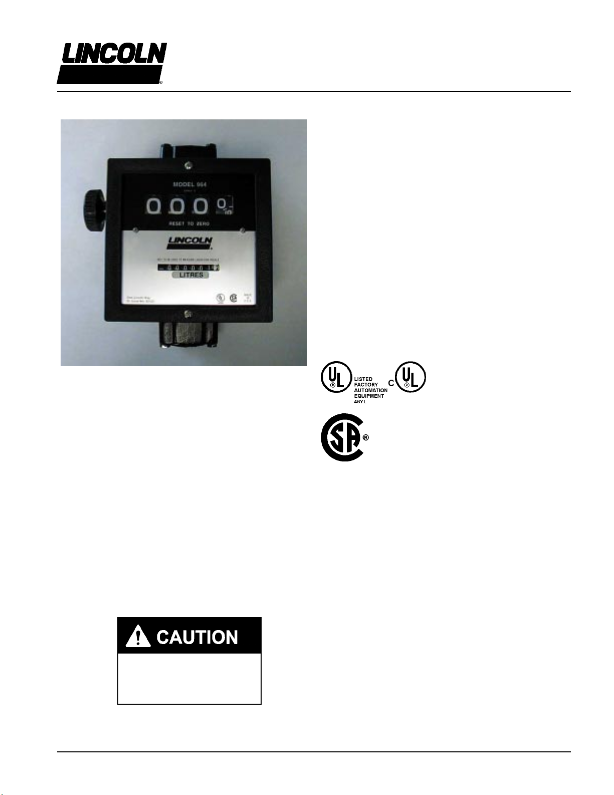
Models 961 & 964
Volume Meters
Series D
INSTALLATION
Meters are furnished for vertical piping, up to down flow
(horizontal piping; left to right flow) unless otherwise speci-
fied. Flow ports can be changed to any of four positions for
horizontal or vertical piping and for either direction of flow.
1. Determine direction for fluid to flow.
2. Install meter observing directional arrow on casting.
3. Remove four screws (item 28).
4. Rotate meter cover assembly (item 37) to desired
orientation.
5. Replace four screws.
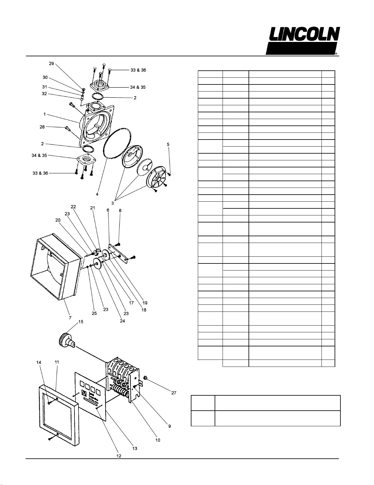
ASSEMBLY & DISASSEMBLY
Meter consists of a chamber housing, measuring chamber,
gear train, counter assembly and cover. Meter can be
completely disassembled without disturbing piping, or
meter can be partially disassembled as required.
Counter Assembly
For access to counter assembly, remove reset knob (item
15) by grasping edges and pulling firmly. Knob is held in
place by a spring clip. Loosen two screws (item 14) and lift
bezel (item 11) off. Remove two screws (item 12) to detach
counter face (item 13). Remove two screws (item 9) to
extract counter (item 10). Reassemble by reversing
procedure.
Meter Chamber Assembly
To expose meter chamber assembly, gear train and seal,
remove four screws (item 28). Meter chamber assembly
consists of upper and lower chambers, a rotating disc and
four screws. Meter chamber assembly (item 3) can be
dislodged by removing four screws (item 5). Reassemble
by reversing procedure.
If replacement of any components of the meter chamber
assembly is required, the complete assembly must be
replaced due to the precise method of its construction. This
assures a proper fit and a correctly operating chamber.
Gear Train and Seal
To disassemble gear train and seal, remove two screws
(item 8) and gear frame (item 6). Remove cluster gear (item
18), washer (item 19), and shaft (item 17). Remove drive
gear (item 24) and washers (item 23) by rotating and pulling
drive gear. Remove O-Ring seal (item 25).
When reassembling seal, lubricate O-Ring with oil or
petroleum jelly and replace in cover. Place washer on drive
gear shaft. Rotate and push shaft through O-Ring and cover
carefully to prevent damage to O-Ring. Shaft must then be
guided into pinion bevel (item 27) if counter has not been
removed. Replace remaining parts to complete assembly
by reversing disassembly procedure.
OPERATING INSTRUCTIONS
For accurate measurement and to prevent meter damage,
meter and piping must always be filled with liquid and free of
air. Meter should be calibrated per instructions in this manual
prior to its use.
1. Reset meter to 0.
2. Meter is ready for use.
MAINENANCE
Meter should operate maintenance free. However, certain
liquids can dry out while in meter housing, causing the meter
to stop. If this happens, meter should be thoroughly cleaned
(see instructions below).
Cleaning Instructions:
Run a flushing fluid through meter. For a more thorough
cleaning, disassemble meter per Assembly & Disassembly
section, Meter Chamber Assembly subsection. Rinse all
meter components. Recalibrate meter following calibration
instructions.
Storage:
If meter is to be stored for a period of time, clean thoroughly.
This will help protect meter from damage.
REPAIR
Meters needing repair should be taken to an authorized
repair shop or returned to factory for service. Meters must
be thoroughly triple-rinsed before being taken in for repair.
PRIOR TO SERVICE, ADHERE TO THE FOLLOWING
INSTRUCTIONS:
If meter was used for a fluid other than a petroleum product,
it must be triple-rinsed and accompanied by a note
indicating the chemicals that have been pumped through
the unit. Meters not adhering to these specifications may be
refused service at either the repair shop or at the factory.
WHEN ORDERING REPAIR PARTS, BE SURE TO GIVE
REPLACEMENT PART NUMBER, DATE OF MANUFACTURE
AND METER SERIES NUMBER. THIS WILL ENSURE THAT
THE CORRECT REPLACEMENT PART IS SUPPLIED.