Lincoln Electric Mobiflex 400-MS User manual

MOBIFLEX 400-MS
MOBIFLEX 400-MS/C
EN User manual
NL Gebruikershandleiding
DE Betriebsanleitung
FR Manuel opérateur
ES Instrucciones para el uso
IT Manuale d’uso
Ref : 86958585
REVISION : A
DATE : 06/2022
Notice Originale
Lincoln Electric
EN
NL
DE
FR
ES
IT
Mobile welding fume extractor
Mobiele lasrookafzuiger
Mobiler Schweißrauchabsauger
Epurateur mobile des fumées de soudure
Aspirador móvil de humos de soldadura
Estrattore mobile per fumi di saldatura

TABLE OF CONTENTS
0507260020/150709/E Mobiflex 400-MS - Mobiflex 400-MS/C 1
NEDERLANDS Pag. ENGLISH Page DEUTSCH Seite
Voorwoord 2 Preface 11 Vorwort 20
1. Inleiding 2 1. Introduction 11 1. Einleitung 20
2. Productbeschrijving 3 2. Product description 12 2. Produktbeschreibung 21
3. Veiligheid 3 3. Safety 12 3. Sicherheitsvorschriften 21
4. Installatie 4 4. Installation 13 4. Installation 22
5. Gebruik 5 5. Use 14 5. Betrieb 23
6. Onderhoud 7 6. Maintenance 15 6. Wartung 25
7. Verhelpen van storingen 9 7. Troubleshooting 18 7. Fehlerbehebung 27
8. Reserveonderdelen 10 8. Spare parts 19 8. Ersatzteile 28
9. Elektrisch schema 10 9. Electrical diagram 19 9. Schaltplan 28
10. Afdanken 10 10. Disposal 19 10. Entsorgung 28
CE verklaring 10 CE declaration 19 EG-Konformitätserklärung 28
FRANÇAIS Page ITALIANO Pag. ESPAÑOL Pág.
Avant-propos 29 Prefazione 39 Preámbulo 48
1. Introduction 29 1. Introduzione 39 1. Introducción 48
2. Description de produit 30 2. Descrizione del prodotto 40 2. Descripción del producto 49
3. Instructions de sécurité 30 3. Istruzioni per la sicurezza 40 3. Normativas de seguridad 49
4. Installation 31 4. Installazione 41 4. Instalación 50
5. Utilisation 32 5. Uso 42 5. Uso 51
6. Entretien 32 6. Mantenimento 44 6. Mantenimiento 53
7. Réparation des pannes 36 7. Riparazione dei guasti 46 7. Subsanación de fallos 55
8. Pièces détachées 37 8. Pezzi di ricambi 47 8. Piezas de recambio 56
9. Pièces détachées 38 9. Diagramma elettrico 47 9. Esquema eléctrico 57
10. Mettre au rancart 38 10. Scartare 47 10. Desechar 57
Déclaration de Conformité 38 Dichiarazione CE 47 Declaración CE 57

0507260020/150709/E Mobiflex 400-MS - Mobiflex 400-MS/C NL - 2
NEDERLANDS
Gebruik van deze handleiding
Deze handleiding is bedoeld als naslagwerk waarmee
professionele, geschoolde en daartoe bevoegde gebruikers het
aan de voorzijde van dit document vermelde product op veilige
wijze kunnen installeren, gebruiken, onderhouden en
repareren.
Pictogrammen en symbolen
In deze handleiding worden de volgende pictogrammen en
symbolen gebruikt:
Service en technische ondersteuning
Voor informatie betreffende specifieke afstellingen,
onderhouds- of reparatiewerkzaamheden die buiten het bestek
van deze handleiding vallen, gelieve contact op te nemen met
de leverancier van het product. Deze is altijd bereid u te helpen.
Zorg ervoor dat u de volgende gegevens bij de hand heeft:
- productnaam
-serienummer
Deze gegevens vindt u op het identificatieplaatje.
1.1 Identificatie van het product
Het identificatieplaatje bevat o.a. de volgende gegevens:
• productnaam
•serienummer
• aansluitspanning en frequentie
•vermogen
1.2 Algemene beschrijving
De Mobiflex 400-MS (Mobiflex 400-MS/C) is een mobiele
lasrookafzuiger met filter en geïntegreerde ventilator, waar een
flexibele afzuigarm of afzuigslang op aangesloten wordt.
De machine bevat een aluminium vonkenvanger en een rond
cellulose filterpatroon. Dit filterpatroon is voorzien van een
precoat dat de levensduur van het filter verlengt en de initiële
efficiency verhoogt. De machine is voorzien van het RotaPulse
systeem voor automatische, segmentsgewijze reiniging van het
filterpatroon door middel van perslucht. In het geval van de
Mobiflex 400-MS wordt de perslucht extern aangevoerd, terwijl
de Mobiflex 400-MS/C is uitgevoerd met een ingebouwde
compressor. De stof- en vuildeeltjes komen uiteindelijk in de
stoflade onderaan de machine terecht.
Dankzij de vier transportwielen (waarvan twee zwenkwielen), is
de Mobiflex 400-MS bij uitstek geschikt voor gebruik in relatief
kleine werkplaatsen of bij vervuilingsbronnen zonder vaste
opstelling.
De afzuigarm of -slang moet apart worden besteld.
Tenzij anders vermeld, heeft deze handleiding tevens
betrekking op de volgende machines voorzien van BGIA-
certificaat:
- Mobiflex 400-MS/BIA
- Mobiflex 400-MS/C-BIA
BGIA is een Duits testinstituut (Institut für Arbeitsschutz/
Institute for Occupational Safety and Health).
1.3 Productcombinaties
De machine moet met een van de volgende producten worden
gecompleteerd:
- LFA 3.0 (afzuigarm)
- LFA 4.0 (afzuigarm)
- LFA 3.1 (afzuigarm)
- LFA 4.1 (afzuigarm)
- SUS 5/203 (afzuigslang)
1.4 Opties en accessoires
Voor de machine zijn geen opties en accessoires beschikbaar.
1.5 Technische gegevens
1.6 Omgevingscondities
1.7 Transport van de machine
Euromate B.V. kan op geen enkele wijze verantwoordelijk
worden gesteld voor transportschade na aflevering. Ga altijd
voorzichtig met de machine en de bijbehorende afzuigarm cq.
-slang om.
Voordat eventueel transport plaatsvindt, moet de afzuigarm
altijd volledig losgekoppeld worden. Koppel de afzuigarm los
door de montageprocedure in omgekeerde volgorde uit te
voeren. Hierna kunnen de machine en de afzuigarm in de
VOORWOORD
TIP
Suggesties en adviezen om de betreffende taken of
handelingen gemakkelijker te kunnen uitvoeren.
VOORZICHTIG!
Procedures die -wanneer ze niet met de nodige
voorzichtigheid worden uitgevoerd- schade aan het
product, de omgeving of het milieu tot gevolg kunnen
hebben.
WAARSCHUWING!
Procedures die -wanneer ze niet met de nodige
voorzichtigheid worden uitgevoerd- ernstige schade
aan het product of lichamelijk letsel tot gevolg kunnen
hebben.
WAARSCHUWING!
Gevaar voor elektrische spanning.
WAARSCHUWING!
Belangrijke waarschuwing ter voorkoming van brand.
1 INLEIDING
Afmetingen L x B x H 1210 x 810 x 1020 mm
Gewicht - Mobiflex 400-MS: 105 kg
- Mobiflex 400-MS/C: 115 kg
Opgenomen vermogen 0,75 kW
Vrijblazend luchtdebiet 2400 m3/h
Netto afzuigcapaciteit 1250 m3/h (schoon filter)
Min. debiet 600 m3/h
Motortoerental 2800 rpm
Filterklasse:
-vonkenvanger
- hoofdfilter LongLife FCC 30
Alleen voor machines met
BGIA-certificaat:
- efficiency
- G2 volgens DIN-EN 779
- M volgens NEN-EN-IEC
60335-2-69
- W2 (99,50%)
Filteroppervlakte 30 m2
Benodigde persluchtkwaliteit vrij van olie en vocht conform
ISO 8573-3 klasse 6
Benodigde persluchtdruk 400-500 kPa (4-5 bar)
Persluchtverbruik 60 nl/min.
Isolatieklasse F
Beschermingsklasse IP 50
Zie het beschikbare productinformatieblad voor
gedetailleerde specificaties.
Min. bedrijfstemperatuur 5°C (41°F)
Nom. bedrijfstemperatuur 20°C (68°F)
Max. bedrijfstemperatuur 45°C (113°F)
Max. relatieve vochtigheid 80% (niet condenserend)

0507260020/150709/E Mobiflex 400-MS - Mobiflex 400-MS/C NL - 3
originele verpakking op een pallet vervoerd worden.
Let erop dat de machine en de afzuigarm niet van de pallet
kunnen schuiven ter voorkoming van beschadigingen.
2.1 Componenten
De machine bestaat uit de volgende hoofdcomponenten:
Fig. 2.1
A bedieningspaneel
B afdekkap bedieningspaneel
Cfilterkap
D magneetklep (24 VAC)
Esterknop
F hoofdfilter LongLife filter FCC 30
G uitblaasrooster
Hbehuizing
I transportwielen
J stoflade (± 25 liter)
K filterreinigingsunit met snelontluchtventiel
L vonkenvanger (voorfilter)
M compressor (alleen Mobiflex 400-MS/C)
N zwenkwielen
Omotor
P ventilatorhuis
Q ventilator
R reduceerventiel (aleen Mobiflex 400-MS)
Snetsnoer
T persluchtaansluiting (alleen Mobiflex 400-MS/C)
Fig. 2.1: Hoofdcomponenten
2.2 Werking
De Mobiflex 400-MS (Mobiflex 400-MS/C) werkt volgens het
recirculatieprincipe. De lasrook wordt door de ventilator
aangezogen en komt via het ventilatorhuis bij de vonkenvanger
in het hart van het filter. Hier worden de grotere deeltjes en
eventuele vonken afgescheiden.
Vervolgens wordt de lucht door het hoofdfilter gereinigd. Via het
uitblaasrooster komt de gereinigde lucht weer op de werkplek
terug.
Wanneer het filter zwaar vervuild raakt - en dientengevolge de
afzuigcapaciteit sterk afneemt - activeert een
drukverschilschakelaar het RotaPulse perslucht-
reinigingsmechanisme dat vervolgens met behulp van
sectiegestuurde persluchtstoten het filter grondig reinigt. Bij de
Mobiflex 400-MS wordt de perslucht extern toegevoerd, terwijl
de Mobiflex 400-MS/C een ingebouwde compressor bevat.
De stof- en vuildeeltjes komen uiteindelijk in de stoflade
terecht.
Algemeen
De fabrikant aanvaardt geen enkele aansprakelijkheid voor
schade of letsel veroorzaakt door het niet (strikt) naleven van
de veiligheidsvoorschriften en -instructies in deze handleiding,
dan wel door onachtzaamheid tijdens installatie, gebruik,
onderhoud en reparatie van het op de voorzijde van dit
document vermelde product en de eventuele bijbehorende
accessoires.
Afhankelijk van de specifieke werkomstandigheden of gebruikte
accessoires kunnen aanvullende veiligheids-instructies nodig
zijn. Neem s.v.p. direct contact op met uw leverancier indien u
bij het gebruik van het product een potentieel gevaar hebt
geconstateerd.
De gebruiker van het product is te allen tijde volledig
verantwoordelijk voor de naleving van de plaatselijk
geldende veiligheidsvoorschriften en -richtlijnen.
Respecteer dan ook alle veiligheidsvoorschriften en
-richtlijnen die van toepassing zijn.
Gebruikershandleiding
• Een ieder die aan of met het product werkt, dient van de
inhoud van deze handleiding op de hoogte te zijn en de
instructies daarin nauwgezet op te volgen. De bedrijfsleiding
dient het personeel aan de hand van de handleiding te
onderrichten en alle voorschriften en aanwijzingen in acht te
nemen.
• Wijzig nooit de volgorde van de te verrichten handelingen.
• Bewaar de handleiding steeds in de nabijheid van het
product.
Pictogrammen en instructies op het product (indien
aanwezig)
• Op het product aangebrachte pictogrammen,
waarschuwingen en instructies maken deel uit van de
getroffen veiligheidsvoorzieningen. Ze mogen niet worden
afgedekt of verwijderd en dienen gedurende de gehele
levensduur van het product aanwezig en leesbaar te zijn.
• Vervang of herstel onmiddellijk onleesbaar geworden of
beschadigdepictogrammen, waarschuwingenen instructies.
Gebruikers
• Gebruik van het product is uitsluitend voorbehouden aan
daartoe opgeleide en bevoegde gebruikers. Tijdelijke
werkkrachten en personen in opleiding mogen het product
uitsluitend onder toezicht en verantwoording van vaklui
gebruiken.
• Gebruik uw gezond verstand. Blijf voortdurend opletten en
houd uw aandacht bij het werk. Gebruik het product niet als
u onder invloed bent van drugs, alcohol of medicijnen.
• De machine mag niet worden gebruikt door kinderen of
personen met beperkte fysieke, zintuiglijke of mentale
vermogens, tenzij onder toezicht of instructie.
• Kinderen moeten onder toezicht staan om te voorkomen dat
ze met de machine gaan spelen.
Gebruik volgens bestemming1
Het product is uitsluitend ontworpen voor het afzuigen en
filteren van rook en gassen die vrijkomen tijdens de meest
2PRODUCTBESCHRIJVING
ABC D E FG
JI HKLMNOPQRST
3VEILIGHEID
1. "Gebruik volgens bestemming" zoals vastgelegd in de EN 292-1 is het
gebruik waarvoor het technisch product volgens de opgave van de
fabrikant -inclusief diens aanwijzingen in de verkoopbrochure- geschikt is.
Bij twijfel is dat het gebruik dat uit de constructie, uitvoering en functie van
het product als gebruikelijk naar voren komt. Tot het gebruik volgens
bestemming behoort ook het in acht nemen van de instructies in de
gebruikershandleiding.

0507260020/150709/E Mobiflex 400-MS - Mobiflex 400-MS/C NL - 4
voorkomende lasprocessen. Elk ander of verdergaand gebruik
geldt niet als conform de bestemming. Voor schade of letsel dat
hiervan het gevolg is, aanvaardt de fabrikant geen enkele
aansprakelijkheid. Het product is in overeenstemming met de
vigerende normen en richtlijnen. Gebruik het product uitsluitend
in technisch perfecte conditie, conform de hierboven beschreven
bestemming.
Technische specificaties
De in deze handleiding vermelde specificaties mogen niet
worden gewijzigd.
Modificaties
Modificatie van (onderdelen van) het product is niet toegestaan.
Gebruik
• Inspecteer het product en controleer het op beschadigingen.
Verifieer de werking van de veiligheidsvoorzieningen.
• Controleer de werkomgeving. Laat onbevoegden niet in de
werkomgeving toe.
• Bescherm het product tegen water of vocht.
• Zorg altijd voor voldoende ventilatie, met name in kleine
ruimten.
• Installeer het product nooit voor in-, uit- en doorgangen die
zijn bedoeld voor hulpdiensten.
• Zorg ervoor dat op de werkplek, in de nabijheid van het
product, voldoende goedgekeurde brandblussers aanwezig
zijn.
• Lucht die deeltjes bevat die een bedreiging vormen voor de
gezondheid -zoals chroom, nikkel, beryllium, cadmium,
lood, etc.- mag nooit worden gerecycled. Deze lucht moet
altijd buiten de werkruimte worden gebracht.
Service, onderhoud en reparatie
• Respecteer de in deze handleiding gegeven
onderhoudsintervallen. Achterstallig onderhoud kan leiden
tot hoge kosten voor reparaties en revisies en kan
aanspraken op garantie doen vervallen.
• Gebruik altijd door de fabrikant goedgekeurde
gereedschappen, onderdelen, materialen en service-
technieken. Gebruik nooit versleten gereedschap en laat
geen gereedschap in of op het product achter.
• Veiligheidsvoorzieningen die ten behoeve van service,
onderhoud of reparatie zijn verwijderd, moeten na deze
werkzaamheden onmiddellijk worden gemonteerd en op
correct functioneren worden gecontroleerd.
4.1 Uitpakken
Controleer of het product compleet is. De inhoud van de
verpakking bestaat uit:
- mobiele lasrookafzuiger
- flexibele slang 65 cm voor aansluiting van afzuigarm
- bevestigingsmateriaal om de afzuigarm te monteren
- handleiding
- elektrisch schema
Indien er onderdelen ontbreken of beschadigd zijn, neem dan
contact op met uw leverancier.
4.2 Montage van de netstekker
De machine wordt zonder netstekker geleverd.
• Monteer een geschikte netstekker, bij voorkeur een met
fase-omkeerschakeling (alleen 3-fasenmotor).
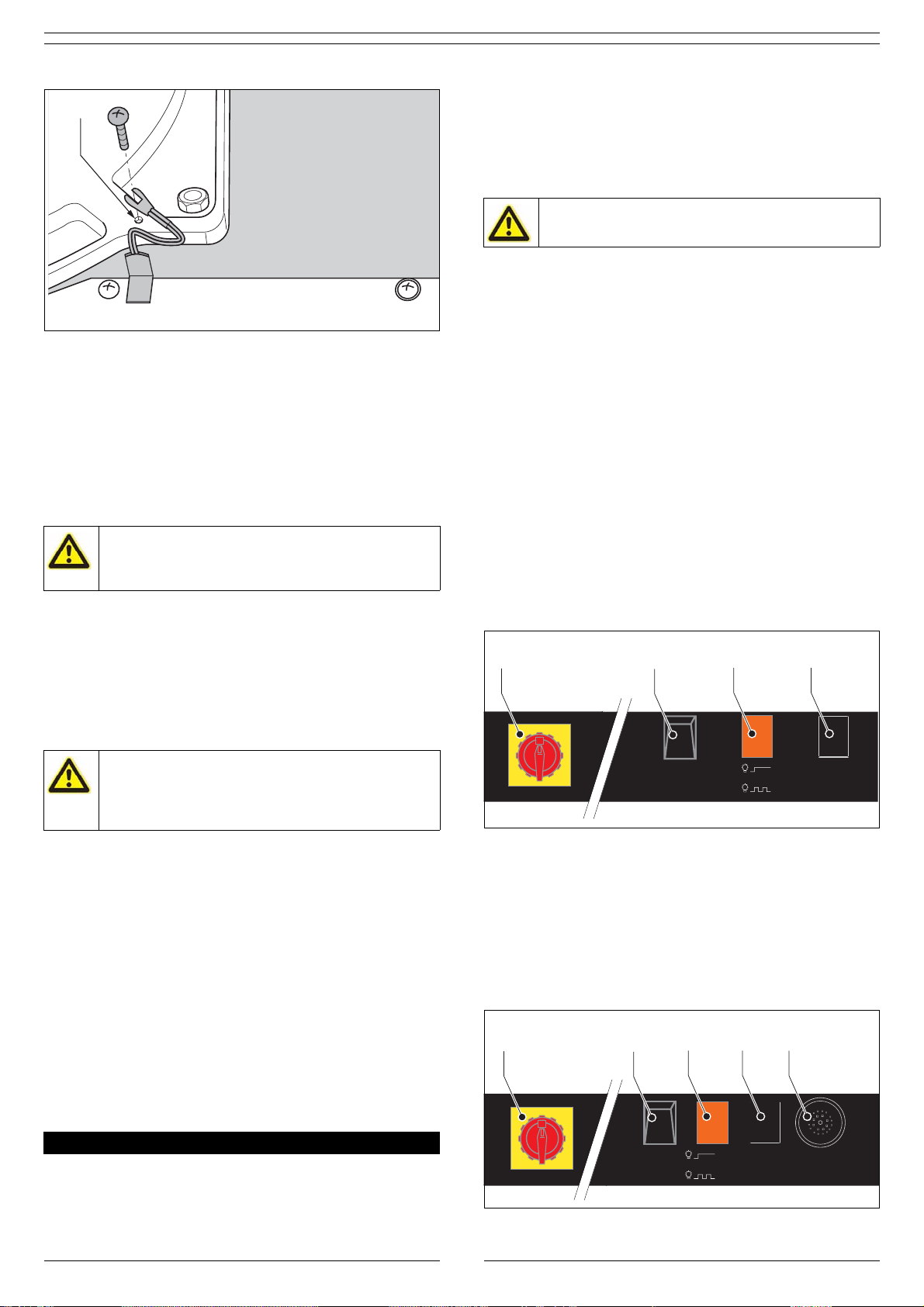
4.3 Aarding van de machine
Wanneer de machine met een afzuigarm wordt uitgevoerd,
moet de machine voor gebruik worden geaard. Machines met
een afzuigslang behoeven niet geaard te worden.
Fig. 4.1
• Maak de rode afdekkap van het bedieningspaneel los en
verwijder deze.
• Monteer het met de afzuigarm meegeleverde draaischarnier.
Zie de betreffende handleiding.
• Bevestig de aardedraad aan het draaischarnier (A).
WAARSCHUWING
Brandgevaar! Het product nooit gebruiken voor:
- afzuiging en/of filtratie van ontvlambare, gloeiende
of brandende deeltjes of vloeistoffen
- afzuiging en/of filtratie van agressieve rook en
gassen (bv. van zuren en alkaline) of scherpe
voorwerpen
- afzuiging en/of filtratie van deeltjes die vrijkomen
bij het lassen aan oppervlakten die met primer zijn
behandeld
- afzuiging van sigaretten, sigaren, tissues of andere
brandende deeltjes, voorwerpen of zuren
WAARSCHUWING
Het product nooit gebruiken voor:
- autogeensnijden
-gutsen
- olienevel
- verfnevel
- zware olienevel in lasrook
- afzuiging van hete gassen (hoger van 45°C
continue)
- slijpen van aluminium en magnesium
- vlamspuiten
- afzuiging van cement, zaagsel, houtsnippers etc.
- alle situaties waarin explosies kunnen voorkomen;
explosieve stoffen/gassen
NB: deze lijst is niet allesomvattend.
LET OP!
Onderhoud mag alleen worden uitgevoerd door
daartoe bevoegd, gekwalificeerd en getraind
personeel, dat gebruik maakt van de juiste
werkmethoden.
WAARSCHUWING!
Wacht na het uitschakelen van de ventilator ten
minste 10 seconden alvorens de machine te openen
voor service-, onderhouds- of reparatiewerk-
zaamheden.
WAARSCHUWING!
Draag altijd een stofmasker en handschoenen bij het
vervangen/reinigen van de filters.
De industriële stofzuiger die gebruikt wordt tijdens
service- en onderhoudswerkzaamheden, moet
voldoen aan stofklasse H volgens de norm EN 60335-
2-69
WAARSCHUWING!
Gebruik de machine nooit zonder vonkenvanger,
hoofdfilter en afzuigarm/-slang.
WAARSCHUWING!
Rijd nooit over het netsnoer. Vermijd contact van de
wielen met hete of scherpe voorwerpen.
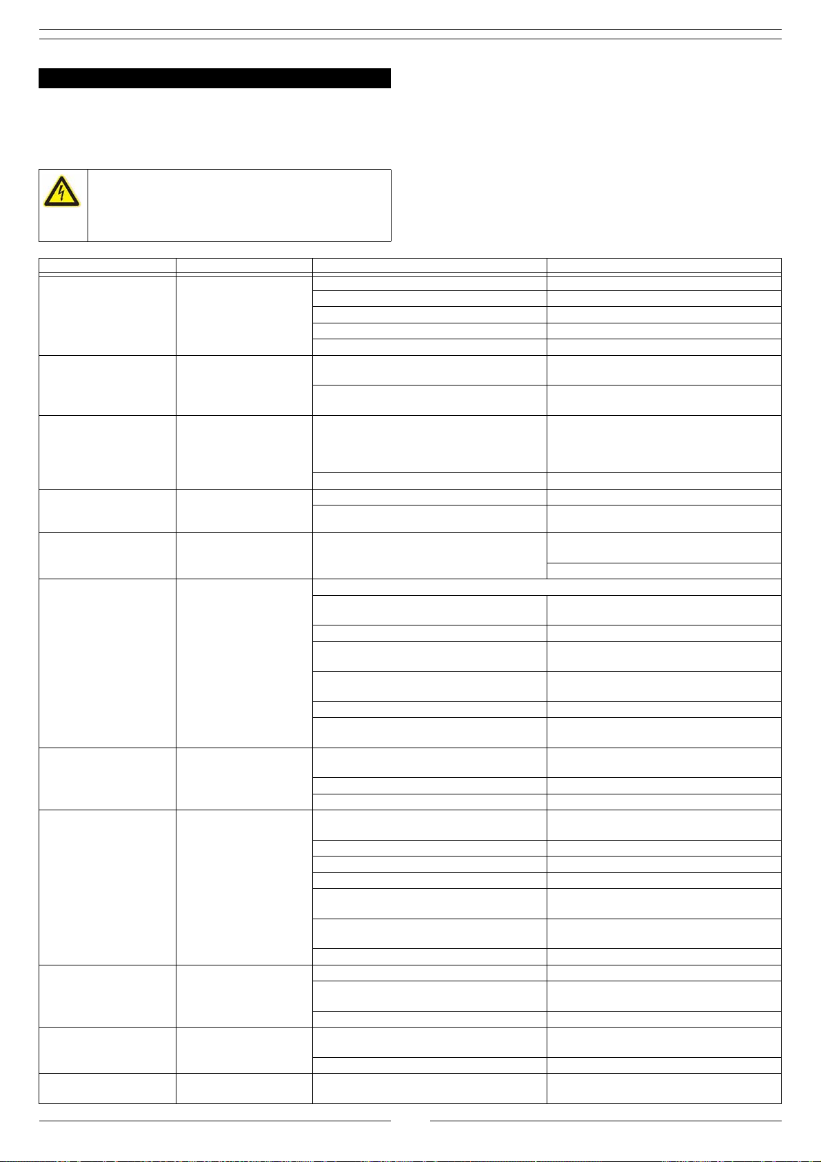
4INSTALLATIE
WAARSCHUWING!
Aansluiting van de stekker dient te geschieden in
overeenstemming met de ter plaatse geldende
voorschriften en is uitsluitend toegestaan aan daartoe
opgeleide, bevoegde service-technici.

0507260020/150709/E Mobiflex 400-MS - Mobiflex 400-MS/C NL - 5
Fig. 4.1: Aarden van de machine
4.4 Persluchtaansluiting (alleen Mobiflex 400-MS)
De Mobiflex 400-MS is niet voorzien van een compressor en dus
afhankelijk van externe persluchttoevoer. Het
filterreinigingsmechanisme werkt op perslucht met een
aanbevolen werkdruk van 400-500 kPa (4-5 bar). Zorg ervoor
dat de werkdruk altijd tussen deze waarden ligt, bij voorkeur op
450 kPa (4,5 bar).
De Mobiflex 400-MS is standaard voorzien van een
reduceerventiel (Fig. 2.1R).
• Sluit de Mobiflex 400-MS aan op perslucht.
4.5 Montage van de afzuigarm/-slang
De machine kan met verschillende typen afzuigarmen of een
afzuigslang worden uitgevoerd. Zie de betreffende handleiding
voor montage van de arm/slang.
4.6 Aansluiting op het net
• Sluit de machine aan op het elektriciteitsnet.
• Controleer de draairichting van de motor (alleen 3-
fasenmotor).
De draairichting kan op verschillende manieren worden
gecontroleerd:
- middels een debietmeter; het debiet aan de afzuigkap moet
minstens 1000 m3/h zijn
- door het controleren van het geluid en de luchtopbrengst
Wanneer de motor een brommend geluid maakt en er
nauwelijks afzuiging plaatsvindt, is de draairiching van de motor
verkeerd. Een juiste draairichting kenmerkt zich door een hoog
luchtvolume bij een laag geluidsniveau. Het verschil kan worden
vastgesteld door het omdraaien van de fasen.
• Wijzig indien nodig de fasenaansluiting.
Alleen voor machines met BGIA-certificaat:
De machines Mobiflex 400-MS/BIA en Mobiflex 400-MS/C-BIA
voldoen aan lasrookklasse “W2”. Lasrookklasse “W2” is geschikt
voor afzuiging en filtratie van lasrook van gelegeerd staal met
een nikkel- en chroomgehalte van <= 30% bij recirculatie van
de gereinigde lucht in de werkruimte.
Let erop dat in geval van kankerverwekkende lasrook, bv.
lasrook die nikkel- en chroomdeeltjes bevat, de bepalingen van
TRGS 560 “Recirculatie van lucht bij het omgaan van
kankerverwekkende stoffen” in acht genomen en aangehouden
dienen te worden.
5.1 Bediening
5.1.1 Bedieningspaneel machines zonder BGIA-certificaat
Het bedieningspaneel is voorzien van de volgende
bedieningsorganen:
Fig. 5.1a
A Hoofdschakelaar
B wipschakelaar VENTILATOR AAN/UIT (FAN ON/OFF).
C Controlelamp:
- REINIGING (CLEANING) UIT: de controlelamp is uit om aan
te geven dat er geen filterreiniging plaatsvindt.
- REINIGING (CLEANING) AAN: de controlelamp is aan om aan
te geven dat de machine bezig is met het
filterreinigingsproces.
- ALARM: de controlelamp knippert om aan te geven dat
het filter verzadigd is en niet meer voldoende kan worden
gereinigd middels automatische filterreiniging. Het kan
ook betekenen dat de persluchtdruk ontoereikend is om
het filter te reinigen.
D Kno REINIGING AAN/UIT - RESET (CLEANING ON/OFF - RESET)
Voor offline reiniging en reset.
Fig. 5.1a: Bedieningspaneel machines zonder BGIA-certificaat
5.1.2 Bedieningspaneel machines met BGIA-certificaat
Fig. 5.1b
Zie paragraaf 5.1.1. Additioneel:
EZoemer
Wanneer de machine in de ALARM-fase overgaat die
aangegeven wordt door een knipperende controlelamp (C),
geeft de zoemer tegelijkertijd een onderbroken signaal. In
normale omstandigheden geeft de zoemer geen signaal.
Fig. 5.1b: Bedieningspaneel machines met BGIA-certificaat
WAARSCHUWING!
Voorkom schade aan het reinigingsmechanisme. Zorg
ervoor dat de perslucht vrij is van olie en vocht (ref.
ISO 8573-3 klasse 6).
VOORZICHTIG!
Vergewis u ervan dat de machine geschikt is voor
aansluiting op het plaatselijke net. Gegevens met
betrekking tot de aansluitspanning en frequentie vindt
u op het betreffende identificatieplaatje.
5GEBRUIK
A
WAARSCHUWING!
Schakel de machine nooit in zonder vonkenvanger,
hoofdfilter en afzuigarm/-slang.
fan on/off cleaning on/off
reset
cleaning
alarm
1
0
ABC D
fan on/off cleaning on/off
reset
cleaning
alarm
1
0
ABC D E

0507260020/150709/E Mobiflex 400-MS - Mobiflex 400-MS/C NL - 6
5.2 Gebruik
Omdat het een mobiele unit betreft, kan deze op iedere
gewenste plaats worden ingezet. Voor een optimaal resultaat
moet de machine zo dicht mogelijk bij de vervuilingsbron wordt
geplaatst.
• Positioneer de kap van de aangesloten afzuigarm (of -slang)
op de aanbevolen afstand van de vervuilingsbron. Zie ook de
handleiding van de betreffende afzuigarm.
• Draai de hoofdschakelaar (Fig. 5.1A) AAN om de
stroomtoevoer de activeren.
• Druk op de wipschakelaar VENTILATOR AAN (I) (Fig. 5.1B)
om de machine in werking te stellen.
• Begin te lassen.
• Druk ca. 20 seconden na het beëindigen van de
laswerkzaamheden op de wipschakelaar VENTILATOR UIT
(Fig. 5.1B) (0) om de machine uit te schakelen.
• Draai de hoofdschakelaar (Fig. 5.1A) UIT om de
stroomtoevoer te onderbreken.
Als de aangesloten afzuigarm is voorzien van een WL
(werklamp) of WL+AST (werklamp + automatische start/stop),
kan de machine ook via de kap worden bediend. Zie de
betreffende handleiding.
5.3 RotaPulse automatisch filterreinigingssysteem
5.3.1 Controlelamp: REINIGING (CLEANING)
Tijdens normaal gebruik (dat wil zeggen met een schoon, niet
verzadigd filter), werkt de machine geheel zelfstandig. Zodra -
als gevolg van een vervuild filter- een minimumdebiet is bereikt,
activeert de drukverschilschakelaar het RotaPulse
persluchtreinigingssysteem, dat vervolgens door middel van
sectiegestuurde persluchtstoten het filter reinigt. De stof- en
vuildeeltjes vallen in de stoflade.
Tijdens het automatische filterreinigingsproces is de
controlelamp (Fig. 5.1C) aan (CLEANING). Het reinigingssysteem
stopt wanneer het debiet weer voldoende is.
Deze procedure wordt online reiniging genoemd.
Wanneer geen laswerkzaamheden plaatsvinden tijdens het
automatische filterreinigingsproces, zal de ventilator na iedere
vier persluchtstoten gedurende 30 seconden even gaan draaien
om het drukverschil te controleren. Dit gebeurt maximaal 15
keer.
Wanneer het debiet na 60 persluchtstoten nog niet voldoende is,
zal de controlelamp overgaan in de ALARM-fase.
• Ga in dit geval verder met paragraaf 5.3.2.
5.3.2 Controlelamp: ALARM
Wanneer de controlelamp () knippert (ALARM), ga dan als volgt
te werk.
•Stopmetlassen.
• Druk op de knop REINIGING AAN/UIT - RESET (Fig. 5.1D)
om de knipperende controlelamp uit te schakelen.
• Zorg ervoor dat de wipschakelaar VENTILATOR AAN/UIT
(Fig. 5.1B) uit (0) is.
• Druk nogmaals op de knop REINIGING AAN/UIT - RESET
(Fig. 5.1D) om offline filterreiniging te starten.
Tijdens de offline reinigingscyclus wordt het gehele filterpatroon
segementsgewijs door persluchtstoten gereinigd. Deze cyclus
duurt ca. een uur.
Wanneer de reinigingscyclus gereed is, kan worden doorgegaan
met de laswerkzaamheden.
Wanneer de machine wordt ingeschakeld en de controlelamp
meteen of kort na de reinigingscyclus weer begint te knipperen,
is het LongLife hoofdfilter verzadigd en moet het vervangen
worden.
• Zie voor vervanging van het hoofdfilter paragraaf 6.2.1.
5.3.3 Off-line reiniging
Voor een efficiëntere filterreiniging, wordt aanbevolen om
regelmatig een offline reinigingscyclus uit te voeren. De meest
geschikte reinigingsinterval is een ervaringskwestie. Als richtlijn
kan twee maal per week worden aangehouden, bijvoorbeeld na
werktijd.
Om een offline reinigingscyclus uit te voeren, ga als volg te
werk.
• Zorg ervoor dat de wipschakelaar VENTILATOR AAN/UIT
(Fig. 5.1B) uit (0) is.
• Druk op de knop REINIGING AAN/UIT - RESET (Fig. 5.1D)
om offline reiniging te starten.
De offline reinigingscyclus duurt ca. een uur.
LET OP!
Plaats de machine niet op plaatsen waar deze is
blootgesteld aan trillingen of aan warmtestraling
afkomstig van warmtebronnen.
WAARSCHUWING!
Om een optimaal filterrendement te garanderen, het
offline filterreinigingssysteem niet activeren binnen
de eerste 10 bedrijfsuren na ingebruikname of binnen
10 uur na het vervangen van het filterpatroon.
Alleen voor machines met BGIA-certificaat:
Wanneer de machine in de ALARM-fase overgaat die
aangegeven wordt door een knipperende
controlelamp, geeft de zoemer tegelijkertijd een
onderbroken signaal.
WAARSCHUWING!
Gebruik de machine niet tijdens een offline
reinigingscyclus.
Indien gewenst, kan de offline reinigingscyclus worden
onderbroken door het indrukken van de knop
REINGING AAN/UIT - RESET (Fig. 5.1D).
WAARSCHUWING!
Vervuiling of verzadiging van het filterpatroon kan
leiden tot een afname van de afzuigcapaciteit,
waardoor er minder lasrook wordt afgezogen.
Stop daarom onmiddellijk met lassen wanneer de
machine in de ALARM-fase overgaat.
LET OP!
Zorg voor de beschikbaarheid van perslucht in geval
van offline reiniging na werktijd.
Alleen voor machines met BGIA-certificaat:
De zoemer geeft tijdens offline reining géén signaal.
WAARSCHUWING!
Gebruik de machine niet tijdens een offline
reinigingscyclus.
Indien gewenst, kan de offline reinigingscyclus worden
onderbroken door het indrukken van de knop
REINGING AAN/UIT - RESET (Fig. 5.1D).

0507260020/150709/E Mobiflex 400-MS - Mobiflex 400-MS/C NL - 7
De machine is ontworpen om gedurende lange tijd probleemloos
te functioneren met een minimum aan onderhoud. Om dit te
garanderen zijn echter enkele eenvoudige, regelmatig uit te
voeren onderhouds- en reinigingswerkzaamheden noodzakelijk
die in dit hoofdstuk worden beschreven. Indien u met de nodige
voorzichtigheid te werk gaat en regelmatig onderhoud uitvoert,
zullen eventuele problemen veelal ontdekt en gecorrigeerd
kunnen worden voordat ze tot stilstand leiden.
De aangeven onderhoudsintervallen kunnen variëren
afhankelijk van de specifieke arbeids- en
bedrijfsomstandigheden. Daarom wordt aanbevolen - naast het
hier aangegeven periodieke onderhoud- de machine jaarlijks
aan een grondige, algehele inspectie te onderwerpen. Neem
hiertoe contact op met uw leverancier.
6.1 Periodiek onderhoud
De met een [*] aangegeven onderhoudswerkzaamheden in
onderstaande tabel mogen door de gebruiker worden
uitgevoerd; de overige werkzaamheden zijn voorbehouden aan
daartoe opgeleide en bevoegde service-technici.
Periodiek onderhoud moet conform TRGS 560 worden
uitgevoerd.
6.2 Vervangen van de filters
6.2.1 LongLife hoofdfilter
De vervangingsfrequentie van het filter is een ervaringskwestie,
aangezien de levensduur sterk afhankelijk is van het lasproces,
de samenstelling van de lasrook, de lasintensiteit en de
vochtigheidsgraad.
Vervang het hoofdfilter:
- wanneer de controlelamp blijft knipperen (kort) na een offline
reinigingscylus; of
- zodra de afzuigcapaciteit ontoereikend wordt; of
- bij beschadiging.
Alleen voor machines met BGIA-certificaat (additioneel):
Vervang het hoofdfilter:
- wanneer de zoemer een onderbroken signaal blijft geven
terwijl het reinigngsmechanisme in bedrijf is.
Vervang het hoofdfilter als volgt.
Fig. 6.1
• Schakel de machine uit en koppel los van het net.
• Draai de sterknop (A) los en verwijder de filterkap (B).
Fig. 6.1: Openen van de filterkap
6ONDERHOUD
WAARSCHUWING
Achterstallig onderhoud kan leiden tot brand.
WAARSCHUWING
Schakel de machine altijd uit alvorens onderstaande
werkzaamheden uit te voeren. Lees eerst de
onderhoudsvoorschriften vooraan in deze handleiding.
WAARSCHUWING!
Het is niet toegestaan de filters door middel van
blazen, schudden enz. te reinigen.
Onderdeel Actie Frequentie
1-3
maanden Elke 3
maanden Elke 6
maanden Elke 12
maanden
Behuizing Reinig de buitenkant van de machine met een niet-
agressief schoonmaakmiddel. X [*]
Reinig de binnenkant van de machine met behulp van een
industriële stofzuiger en verwijder het stof uit het
filtercompartiment.
X [*]
Vonkenvanger Reinig de vonkenvanger met behulp van een industriële
stofzuiger. X [*]
Hoofdfilter Controleer het filter op beschadigingen, vervuiling en
verzadiging. Indien nodig vervangen. X [*]
Filterreinigings-
mechanisme Controleer -via handmatige bediening- de werking van
het filterreinigingsmechanisme (ronddraaien, lekkage). X
Stoflade Controleer de stoflade. Indien nodig legen. X [*]
Ventilator Controleer de ventilator en het ventilatorhuis op
aangekoekt vuil. Indien nodig reinigen. X
Controleer het afdichtingsmateriaal bij de ventilator.
Indien nodig vervangen. X
Netsnoer Controleer het netsnoer op beschadigingen. Indien nodig
repareren of vervangen. Vooraf aan
elk gebruik
X [*]
LET OP!
Draag altijd een stofmasker en handschoenen bij het
vervangen/reinigen van de filters.
WAARSCHUWING!
Weer voorzichtig met het vervangen van het
hoofdfilter; het is voorzien van een precoat.
A
B
C

0507260020/150709/E Mobiflex 400-MS - Mobiflex 400-MS/C NL - 8
Fig. 6.2
• Til het hoofdfilter (A) omhoog uit de behuizing.
• Verpak het gebruikte filter in de plastic zak waarin het
nieuwe filter is geleverd. Sluit de zak goed af.
• Reinig de vonkenvanger (B) en het filtercompartiment (C)
met behulp van een industriële stofzuiger.
• Plaats een nieuw LongLife hoofdfilter.
• Bevestig de gedemonteerde onderdelen in omgekeerde
volgorde.
Fig. 6.2: Vervangen van het filter
6.2.2 Vonkenvanger
Vervang de vonkenvanger (Fig. 6.2B):
- wanneer deze vervuild of verzadigd is en niet meer met een
stofzuiger kan worden gereinigd; of
- bij beschadiging.
6.3 Het legen van de stoflade
Vuil- en stofdeeltjes uit het hoofdfilter komen in de stoflade
onderaan de machine terecht. Om te voorkomen dat de stoflade
overstroomt en doordoor de werkplaats vervuilt, moet deze
regelmatig geleegd worden. Zie paragraaf 6.1voor de frequentie
van het legen van de stoflade.
Fig. 6.3
• Draai de sterknop (B) los, die bereikbaar is via de onderzijde
aan de achterkant van de machine.
• Neem de stoflade voorzichtig uit.
De stoflade kan op verschillende wijzen worden geleegd:
- met behulp van een industriële stofzuiger (aanbevolen
manier); of
- door te stoflade te legen in een plastic zak.
• Leeg de stoflade. Wanneer de stoflade in een plastic zak
wordt geleegd, sluit deze goed af.
• Schuif de stoflade terug in de machine.
• Draai de sterknop zorgvuldig aan zodat de stoflade
luchtdicht wordt afgesloten.
Fig. 6.3: Het legen van de stoflade
Wanneer de vonkenvanger beschadigd is, wordt
aanbevolen om ook het hoofdfilter te vervangen.
LET OP!
Draag altijd een stofmasker en handschoenen bij het
legen van de stoflade.
WAARSCHUWING!
Open de stoflade nooit wanneer de ventilator draait.
A
B
C
B
A

0507260020/150709/E Mobiflex 400-MS - Mobiflex 400-MS/C NL - 9
Wanneer de machine niet (correct) functioneert, raadpleeg dan
de volgende checklist om te zien of u het probleem zelf kunt
verhelpen. Is dit niet het geval, neem dan contact op met uw
leverancier.
7 VERHELPEN VAN STORINGEN
WAARSCHUWING
Schakel de machine altijd uit en onkoppel deze van
het net alvorens onderstaande werkzaamheden uit te
voeren. Lees eerst de onderhoudsvoorschriften
vooraan in deze handleiding.
Signalering Probleem Mogelijke oorzaak Oplossing
Motor start niet. Machine werkt niet. Geen netspanning. Controleer de netspanning
Netsnoer defect. Repareer of vervang het netsnoer.
Losse contacten Herstel de contacten.
Motorbeveiligingsschakelaar defect. Vervang de motorbeveiligingsschakelaar.
Motor defect. Repareer of vervang de motor.
Motor maakt een
brommend geluid,
maar draait niet.
Machine werkt niet. Motor gebruikt 2 fasen (alleen bij 3-
fasenmotoren). Herstel de fase-aansluiting.
Motorcondensator defect/niet
aangesloten (alleen 1-fasemotoren). Herstel of vervang de motorcondensator.
Motor stop uit zichzelf. Machine werkt niet. Thermisch relais geactiveerd. Laat de machine enige tijd afkoelen.
Controleer de instelling van het thermisch
relais (NTR) aan de hand van het
elektrisch schema.
Motor defect. Repareer of vervang de motor.
Controlelamp brandt
niet tijdens
reinigingsproces.
Geen indicatie. Controlelamp defect. Vervang de controlelamp.
Besturingsprint defect. Vervang de besturingsprint.
Controlelamp knippert
(ALARM). Onvoldoende
afzuigcapaciteit Verzadigd hoofdfilter. Voer een offline reinigingscyclus uit (zie
5.3.3).
Vervang het hoofdfilter (zie 6.2.1).
De controlelamp blijft
knipperen (ALARM). Geen automatische
filterreiniging Filterreinigingsmechanisme defect:
- 24 VAC magneetklep defective Vervang de magneetspoel of het
membraan.
- besturingsprint defect Vervang de besturingsprint.
- filterreinigingsmechanisme defect of
versleten Vervang het filterreinigingsmechanisme.
- geen perslucht of te lage persluchtdruk Controleer het persluchtsysteem en/of de
persluchtaansluiting.
- drukverschilschakelaar defect. Vervang de drukverschilschakelaar.
- compressor defect (alleen Mobiflex
400-MS/C) Vervang de compressor.
Machine reageert niet
op het indrukken van
de knop REINIGING
AAN/UIT - RESET.
Activeren van offline
reiniging en reset niet
mogelijk.
Knop REINIGING AAN/UIT - RESET
defect. Vervang de knop.
Besturingsprint defect. Vervang de besturingsprint.
24 VAC voeding defect. Herstel de 24 VAC voeding.
Onvoldoende
afzuigcapaciteit. Machinewerkt nietnaar
behoren. Motordraairichting verkeerd (alleen
driefasenmotoren). Wijzig de draairichting.
Ventilator vervuild. Reinig de ventilator.
Uitblaasrooster geblokkeerd. Verwijder blokkering uit uitblaasrooster.
Hoofdfilter vervuild of verzadigd Vervang hoofdfilter (zie 6.2.1).
Vonkenvanger vervuild of verzadigd. Reinig of vervang de vonkenvanger (zie
6.2.2).
Valse lucht aangezogen. Controleer of vervang het
afdichtingsmateriaal.
Filterreinigingsmechanisme defect. Herstel filterreinigingsmechanisme.
Stof of rook uit
filterkap. Vervuiling van de
ruimte. Hoofdfilter beschadigd. Vervang hoofdfilter (zie 6.2.1).
Afdichtingsmateriaal van hoofdfilter
beschadigd. Vervang hoofdfilter (zie 6.2.1).
Hoofdfilter incorrect geplaatst. Plaats het filter op correcte wijze.
Stof of rook uit
stoflade. Vervuiling van de
ruimte. Stoflade incorrect geplaatst. Plaats de stoflade op correcte wijze en
draai de sterknop aan.
Afdichtingsmateriaal van stoflade defect. Vervang het afdichtingsmateriaal.
Trillingen in de
machine. Vervuiling van de
ruimte. Onbalans in de ventilator. Reinig de ventilator.

0507260020/150709/E Mobiflex 400-MS - Mobiflex 400-MS/C NL - 10
Voor de machine zijn de volgende reserveonderdelen
verkrijgbaar (zie exploded view Fig. I op pagina 58).
Zie het separaat bijgevoegde elektrisch schema.
Voer de machine na het einde van de levensduur af conform de
lokaal geldende voorschriften en/of richtlijnen.
EG-verklaring van overeenstemming
(volgens bijlage II A van de Machinerichtlijn)
Wij, Euromate B.V., Wezelkoog 11, 1822 BL Alkmaar, Nederland,
verklaren geheel onder eigen verantwoordelijkheid dat het
product/de producten:
- Mobiflex 400-MS
- Mobiflex 400-MS/C
- Mobiflex 400-MS/BIA
- Mobiflex 400-MS/C-BIA
waarop deze verklaring betrekking heeft, in overeenstemming
is/zijn met de bepalingen van de volgende richtlijn(en):
- 2006/42/EG
- EMC 89/336/EG
-73/23/EG
en (in voorkomend geval) in overeenstemming is/zijn met de
volgende norm(en) of ander(e) normatie(f)(ve) document(en):
Alkmaar, Nederland, 1 augustus 2009
C.J.M. Knijn
Chief Operations Officer
8 RESERVEONDERDELEN
Artikelnr. Omschrijving
Mobiflex 400-MS en Mobiflex 400-MS/C algemeen
0042000040 Membraanventiel
0046020040 Drukregelventiel + manometer
0046030010 Overdrukventiel 6-10 bar
0050101240 Slangset LFA voor montage op mobiele unit
0102080110 Vonkenvanger Mobiflex 400-MS/Statiflex 400-MS (HD)
0324150120 Controlelamp 28V, geel
0326701020 Besturingsprint Mobiflex 400-MS/Statiflex 400-MS
0328050120 Hoofdschakelaar VCO
0328050130 Wipschakelaar
0328290010 Reset/startschakelaar
0328410130 Relais MC2A
0334100200 Transformator 50W/24V 115/230/400V
0340000110 Zekering 2,0 A
0609590110 Starlock 22 mm
0612010220 Pasring 19x1
0708020140 Aluminium ventilatorwiel 50Hz
0708020150 Aluminium ventilatorwiel 60Hz
0801400010 Behuizing SF 1400/2400/M.100-NF/mobiele units,
motorzijde
0805030010 Wiel Ø 250 mm zwart
0805040010 Zwenkwiel Ø 125 mm met rem
0805040050 Zwenkwiel Ø 125 mm zonder rem
0806014020 Sterknop M8
0810100050 Pakking membraanventiel
0830301030 Afdichtrubber stoflade
0830301050 Afdichtrubber
0840101030 Manchet Ø 203 mm
9823020700 Filterkap M.400-MS incl. uitblaasrooster
9824000020 Drukverschilschakelaar Mobiflex 400-MS (800 Pa)
9824000090 Zuigerhuis
9850040080 Wieldoppen rood M.200-M/400-MS/300-E (2 stuks)
9850060110 LongLife filter FCC 30
Mobiflex 400-MS 400V/3ph/50Hz
0320000100 Motor 0,75kW, 230-400V/3ph/50Hz
0328400090 Thermisch relais NTR 1.7-2.4A
Mobiflex 400-MS 230/3ph/50Hz
0320000100 Motor 0,75kW, 230-400V/3ph/50Hz
0328400120 Thermisch relais NTR 3.0-4.7A
Mobiflex 400-MS 230/1ph/50Hz
0321012030 Motor 0,75kW, 115-230V/1ph/50-60Hz
0328400130 Thermisch relais NTR 4.0-6.3A
Mobiflex 400-MS 115/1ph/50Hz
0321012030 Motor 0,75kW, 115-230V/1ph/50-60Hz
0328400160 Thermisch relais NTR 10-14A
Mobiflex 400-MS/BIA 230/1ph/50Hz
0321012030 Motor 0,75kW, 115-230V/1ph/50-60Hz
0328400130 Thermisch relais NTR 4.0-6.3A
0360000020 Zoemer Mobiflex 400-MS-BIA
Mobiflex 400-MS/C 400V/3ph/50Hz
0041000040 Compressorunit Mobiflex 400-MS 230V/1ph
0320000100 Motor 0,75kW, 230-400V/3ph/50Hz
0328400090 Thermisch relais NTR 1.7-2.4A
Mobiflex 400-MS/C 230V/3ph/50Hz
0041000040 Compressorunit Mobiflex 400-MS 230V/1ph
0320000100 Motor 0,75kW, 230-400V/3ph/50Hz
0328400120 Thermisch relais NTR 3.0-4.7A
Mobiflex 400-MS/C 230V/1ph/50Hz
0041000040 Compressorunit Mobiflex 400-MS 230V/1ph
0321012030 Motor 0,75kW, 115-230V/1ph/50-60Hz
0328400130 Thermisch relais NTR 4.0-6.3A
Mobiflex 400-MS/C-BIA 230V/1ph/50Hz
0041000040 Compressorunit Mobiflex 400-MS 230V/1ph
0321012030 Motor 0,75kW, 115-230V/1ph/50-60Hz
0328400130 Thermisch relais NTR 4.0-6.3A
0360000020 Zoemer Mobiflex 400-MS-BIA
9ELEKTRISCHSCHEMA
10 AFDANKEN
CE VERKLARING
NEN-EN-ISO 1200-1
NEN-EN-ISO 1200-2
NEN-EN-ISO 13857
EN 349
NEN-EN-IEC 60204-1
NEN-EN-55014-1
NEN-EN-55014-2
EN-IEC 61000
Artikelnr. Omschrijving

0507260020/150709/E Mobiflex 400-MS - Mobiflex 400-MS/C EN - 11
ENGLISH
Using this manual
This manual is intended to be used as a work of reference for
professional, well trained and authorised users to be able to
safely install, use, maintain and repair the product mentioned
on the cover of this document.
Pictograms and symbols
The following pictograms and symbols are used in this manual:
Service and technical support
For information about specific adjustments, maintenance or
repair jobs which are not dealt with in this manual, please
contact the supplier of the product. He will always be willing to
help you. Make sure you have the following specifications at
hand:
- product name
- serial number
These data can be found on the identification plate.
1.1 Identification of the product
The identification plate contains, among other things, the
following data:
•productname
• serial number
• supply voltage and frequency
• power consumption
1.2 General description
The Mobiflex 400-MS (Mobiflex 400-MS/C) is a mobile filter unit
with integrated fan that provides extraction and filtration for use
with a flexible extraction arm or extraction hose.
The machine features an aluminum spark arrester and a round
cellulose filter cartridge. This filter cartridge is provided with a
precoat to extend the lifespan and increases initial operating
efficiency of the filter. The machine is fitted with a RotaPulse
system for automatic sectionwise cleaning of the filter cartridge
by compressed air. In case of a Mobiflex 400-MS the
compressed air is externally supplied, whereas the Mobiflex
400-MS/C is equipped with a built-in compressor. The dust and
dirt particles end up in the dust tray underneath the unit.
Thanks to the four transport wheels (two of which are swivel
casters), the machine is extremely suitable to be used in
relatively small facilities or near sources of pollution without a
fixed location.
Extraction arm/hose to be ordered separately.
Unless otherwise stated, this manual refers to the following
BGIA approved machines as well:
- Mobiflex 400-MS/BIA
- Mobiflex 400-MS/C-BIA
BGIA is the German Institute for Occupational Safety and
Health.
1.3 Product combinations
In order to operate the machine, selection of one of the
following products is required:
- LFA 3.0 (extraction arm)
- LFA 4.0 (extraction arm)
- LFA 3.1 (extraction arm)
- LFA 4.1 (extraction arm)
- SUS 5/203 (extraction hose)
1.4 Options and accessories
There are no options and accessories available.
1.5 Technical specifications
1.6 Ambient conditions
1.7 Transport of the machine
Euromate B.V. cannot be held liable for any transportation
damage after delivery of the machine. Always handle the
machine and the accompanying extraction arm/hose with care.
Always completely dismount the extraction arm/hose before
transport. Dismount the arm/hose by executing the mounting
procedure in reverse order. Subsequently the machine and the
arm/hose can be transported on a pallet in the original packing.
To prevent damage, prevent the machine and the arm/hose
from shifting on the pallet.
PREFACE
TIP
Suggestions and recommendations to simplify
carrying out tasks and actions.
CAUTION!
Procedures, if not carried out with the necessary
caution, could damage the product, the workshop or
the environment.
WARNING!
Procedures which, if not carried out with the necessary
caution, may damage the product or cause serious
personal injury.
WARNING!
Denotes risk of electric shock.
WARNING!
Important warning to prevent fire.
1 INTRODUCTION
Dimensions L x W x H 1210 x 810 x 1020 mm
Weight - Mobiflex 400-MS: 105 kg
- Mobiflex 400-MS/C: 115 kg
Power consumption 0,75 kW
Unrestriced airflow 2400 m3/h
Net extraction capacity 1250 m3/h (clean filter)
Min. airflow 600 m3/h
Motor speed 2800 rpm
Filter class:
- spark arrester
- main filter LongLife FCC 30
BGIA approved machines
only:
- efficiency
- G2 according to DIN-EN 779
- M according to NEN-EN-IEC
60335-2-69
- W2 (99,50%)
Filter surface 30 m2
Required compressed air
quality dry and oil-free according to
ISO 8573-3 class 6
Required pressure 400-500 kPa (4-5 bar)
Compressed air consumption 60 nl/min.
Insulation class F
Protection class IP 50
Refer to the available product data sheet for detailed
specifications.
Min. operating temperature 5°C (41°F)
Nom. operating temperature 20°C (68°F)
Max. operating temperature 45°C (113°F)
Max. relative humidity 80% (non condensing)

0507260020/150709/E Mobiflex 400-MS - Mobiflex 400-MS/C EN - 12
2.1 Components
The machine consists of the following main components:
Fig. 2.1
Acontrolpanel
Bcontrolpanelcover
Cfiltercover
D magnetic valve (24 VAC)
Estarknob
F main filter LongLife filter FCC 30
G outlet grid
Hhousing
I transport wheels
J dust tray (± 25 litres)
K filter cleaning unit with quick air relief valve
L spark arrester (pre filter)
M compressor (Mobiflex 400-MS/C only)
Nswivelcasters
Omotor
P extraction fan housing
Qextractionfan
R pressure reducing valve (Mobiflex 400-MS only)
Smainscord
T compressed air connection (Mobiflex 400-MS/C only)
Fig. 2.1: Main components
2.2 Operation
The Mobiflex 400-MS (Mobiflex 400-MS/C) works in accordance
with the recirculation principle. Welding fume is extracted by the
extraction fan and enters the spark arrester via the fan housing.
In the spark arrester the larger particles and any sparks are
separated. Subsequently the air is cleaned by the main filter.
Via the outlet grid in the filter cover the cleaned air is returned
in the workshop.
When the main filter becomes heavily saturated - and
consequently the extraction capacity strongly reduces -, a
pressure difference switch activates the RotaPulse compressed
air cleaning mechanism which thoroughly cleans the filter using
section controlled compressed airjets. In the case of an Mobiflex
400-MS compressed air is supplied externally, whereas the
Mobiflex 400-MS/C is equipped with a built-in compressor.
The dust and dirt particles end up in the dust tray.
General
The manufacturer does not accept any liability for damage to
the product or personal injury caused by ignoring of the safety
instructions in this manual, or by negligence during installation,
use, maintenance, and repair of the product mentioned on the
cover of this document and any corresponding accessories.
Specific working conditions or used accessories may require
additional safety instructions. Immediately contact your
supplier if you detect a potential danger when using the product.
The user of the product is always fully responsible for
observing the local safety instructions and
regulations. Observe all applicable safety instructions
and regulations.
User manual
• Everyone working on or with the product, must be familiar
with the contents of this manual and must strictly observe
the instructions therein. The management should instruct
the personnel in accordance with the manual and observe all
instructions and directions given.
• Never change the order of the steps to perform.
• Always keep the manual with the product.
Pictograms and instructions on the product (if
present)
• The pictograms, warning and instructions attached to the
product are part of the safety features. They must not be
covered or removed and must be present and legible during
the entire life of the product.
• Immediately replace or repair damaged or illegible
pictograms, warnings and instructions.
Users
• The use of this product is exclusively reserved to well
authorised, trained and qualified users. Temporary
personnel and personnel in training can only use the product
under supervision and responsibility of skilled engineers.
• Use common sense. Stay alert and keep your attention to
your work. Do not use the product when you are under the
influence of drugs, alcohol or medicine.
• The machine is not to be used by children or persons with
reduced physical, sensory or mental capabilities, or lack of
experience and knowledge, unless they have been given
supervision or instruction.
• Children must be supervised not to play with the machine.
Intended use1
The product has been designed exclusively for extracting and
filtering harmful fumes and gases which are released during the
most common welding processes. Using the product for other
purposes is considered contrary to its intended use. The
manufacturer accepts no liability for any damage or injury
resulting from such use. The product has been built in
accordance with state-of-the-art standards and recognised
safety regulations. Only use this product when in technically
perfect condition in accordance with its intended use and the
instructions explained in the user manual.
Technical specifications
The specifications given in this manual must not be altered.
Modifications
Modification of (parts of) the product is not allowed.
2 PRODUCT DESCRIPTION
ABC D E FG
JI HKLMNOPQRST
3SAFETY
1. "Intended use" as explained in EN-292-1 is the use for which the technical
product is suited as specified by the manufacturer, inclusive of his
directions in the sales brochure. In case of doubt it is the use which can be
deducted from the construction, the model and the function of the
technical product which is considered normal use. Operating the machine
within the limits of its intended use also involves observing the instructions
in the user manual.

0507260020/150709/E Mobiflex 400-MS - Mobiflex 400-MS/C EN - 13
Use
• Inspect the product and check it for damage. Verify the
functioning of the safety features.
• Check the working environment. Do not allow unauthorised
persons to enter the working environment.
• Protect the product against water and humidity.
• Make sure the room is always sufficiently ventilated; this
applies especially to confined spaces.
• Never install the product in front of entrances and exits
which must be used for emerency services.
• Make sure that the workshop, in the vicinity of the product,
contains sufficient approved fire extinguishers.
• Air containing particles such as chromium, nickel, beryllium,
cadmium, lead etc., which is a health hazard, should never
be recycled. This air must always be brought outside the
working area.
Service, maintenance and repairs
• Observe the maintenance intervals given in this manual.
Overdue maintenance can lead to high costs for repair and
revisions and can render the guarantee null and void.
• Always use tools, materials, lubricants and service
techniques which have been approved by the manufacturer.
Never use worn tools and do not leave any tools in or on the
product.
• Safety features which have been removed for service,
maintenance or repairs, must be put back immediately after
finishing these jobs and it must be checked that they still
function properly.
4.1 Unpacking
Check that the product is complete. The package should
contain:
- mobile welding fume extractor
- flexible hose 65 cm for connecting extraction arm
- hardware for mounting extraction arm
- manual
- electrical diagram
If parts are missing or damaged, contact your supplier.
4.2 Mounting the mains plug
The machine comes without plug.
• Mount an appropriate plug, preferably a plug with phase
inverter (three-phase motor only).
4.3 Earthing the machine
If the machine is to be fitted with an extraction arm, it has to be
earthed before use. Machines with an extraction hose do not
need to be earthed.
Fig. 4.1
• Loosen the red control panel cover and remove it.
• Mount the rotating hinge that is supplied with the extraction
arm. Refer to the corresponding manual.
• Fasten earth cable to rotating hinge (A).
Fig. 4.1: Earthing
4.4 Compressed air connection (Mobiflex 400-MS
only)
The Mobiflex 400-MS is not equipped with a compressor;
compressed air must be supplied by an external source. The
filter cleaning mechanism functions on compressed air with a
recommended working pressure of 400-500 kPa (4-5 bar). Make
sure the working pressure always remains between these
values. Preferred pressure is 450 kPa (4,5 bar).
The Mobiflex 400-MS is provided with a pressure reducing valve
(Fig. 2.1R).
WARNING
Fire hazard! Never use the product for:
- extracting and/or filtering flammable, glowing or
burning particles or solids or liquids
- extracting and/or filtering of aggressive fumes (such
as hydrochloric acid) or sharp particles
- extracting and/or filtering dust particles which are
released when welding surfaces treated with primer
- sucking cigarettes, cigars, oiled tissues, and other
burning particles, objects, and acids
WARNING
Never use the product for:
- oxy-fuel cutting
- arc-air gouging
-oilmist
-paintmist
- heavy oil mist in welding fume
- extraction of hot gases (more than 45°C/113°F
continuously)
- grinding aluminium and magnesium
-flamespraying
- extraction of cement, saw dust, wood dust etc.
- explosive environments or explosive substances/
gases
Note: this is not a limited list.
ATTENTION!
Maintenance should only be performed by authorised,
qualified and trained persons (skilled) using
appropriate work practices.
WARNING!
After switching off the fan, wait at least 10 seconds
before dismounting the machine to carry out service,
maintenance or repair jobs.
ATTENTION!
Always wear face mask and gloves during filter
exchange/cleaning.
Industrial vacuum cleaner used during service and
maintenance should meet dust class H according to
EN 60335-2-69.
WARNING!
Never switch on the machine without spark arrester,
main filter and extraction arm/hose.
ATTENTION!
Never drive over the mains cord. Prevent the wheels
from touching hot or sharp objects.
4 INSTALLATION
CAUTION!
Plugs to be installed in accordance with the National
Electrical Code (NEC) and local requirements. This is
strictly reserved for skilled and authorised service
engineers.
CAUTION!
Prevent damage to the cleaning mechanism. Make
sure that the compressed air is free from oil and
moisture (ref. ISO 8573-3 class 6).
A

0507260020/150709/E Mobiflex 400-MS - Mobiflex 400-MS/C EN - 14
• Connect the Mobiflex 400-MS to compressed air.
4.5 Mounting the extraction arm/hose
The machine can be fitted with different types of extraction
arms or an extraction hose. Refer to the corresponding manual
how to mount the arm/hose.
4.6 Connection to the mains
• Connect the machine to the mains.
• Check the direction of rotation of the motor (three-phase
motor only).
The direction of rotation can be checked in different ways;
- using a flowmeter; airflow at the hood should be min.
1000 m3/h
- by checking the sound and the air volume
If the motor is producing a humming sound and there is hardly
any extraction at all, the direction of rotation of the motor is
wrong. A correct direction of rotation is indicated by a high air
volume at a low sound level. The difference can be checked by
inverting the phases.
• If necessary: invert the connection of the phases.
BGIA approved machines only:
The machines Mobiflex 400-MS/BIA and Mobiflex 400-MS/C-BIA
comply with welding fume class “W2”. Machines of welding fume
class “W2” are suitable for extraction and filtration of welding
fume from alloyed steel with a nickel and chromium content of
<=30% in case of recirculation of the cleaned air in the
workshop.
Please note that in case of extraction of carcinogenic welding
fume, e.g. welding fume containing nickel and chromium
substances, the regulations of TGRS 560 “Recirculation of air in
the handling of carcinogenic hazardous materials” are to be
taken into account and respected.
5.1 Controls
5.1.1 Control panel non-BGIA machines
The control panel contains the following controls:
Fig. 5.1a
AMainswitch
B FAN ON/OFF tumbler switch
C Control light:
- “CLEANING” OFF: the control light is off indicating that no
filter cleaning takes place
- “CLEANING” ON: the control light is on indicating that the
machine is busy performing the self-cleaning process
- “ALARM”: the control light blinks indicating that the filter
is saturated and cannot be cleaned sufficiently in the
automatic cleaning mode. It may also indicate that the
pressure is too low to clean the filter.
D CLEANING ON/OFF - RESET button
For off-line filter cleaning and reset.
Fig. 5.1a: Control panel non-BGIA machines
5.1.2 Control panel BGIA approved machines
Fig. 5.1b
Refer to section 5.1.1. Additionally:
EBuzzer
When the machine enters the ALARM stage indicated by a
blinking control light (C), the buzzer emits an intermittent
acoustic signal simultaneously. In normal circumstances the
buzzer will not emit any sound.
Fig. 5.1b: Control panel BGIA approved machines
5.2 Use
Since it concerns a mobile unit, it can be used at any desirable
place. For optimal results the machine must be placed as close
as possible to the source of pollution.
• Position the hood of the connected extraction arm (hose) at
the recommended distance from the source of pollution. Also
refer to the manual of the corresponding extraction arm.
• Turn ON the main switch (Fig. 5.1A) to activate power
supply.
• Press tumbler switch FAN ON (I) (Fig. 5.1B) to put the
machine in operation.
• Start welding.
• Press tumbler switch FAN OFF (0) (Fig. 5.1B). approx. 20
seconds after finishing welding.
• Turn OFF the main switch (Fig. 5.1A) to interrupt power
supply.
If the connected extraction arm is provided with WL (working
light) or WL+AST (working light + automatic start/stop device),
the machine can be controlled on the hood as well. For this
purpose refer to the corresponding manual.
WARNING!
Make sure the machine is suitable for connection to
the local mains. Information about the connection
voltage and frequency can be found on the
identification plate.
5USE
WARNING!
Never switch on the machine without spark arrester,
main filter and extraction arm/hose.
CAUTION!
Do not position the machine in places where it is
exposed to vibrations or heat radiation from heat
sources.
fan on/off cleaning on/off
reset
cleaning
alarm
1
0
ABC D
fan on/off cleaning on/off
reset
cleaning
alarm
1
0
ABC D E

0507260020/150709/E Mobiflex 400-MS - Mobiflex 400-MS/C EN - 15
5.3 RotaPulse automatic filter cleaning system
5.3.1 Control light: CLEANING
During normal operation (i.e. with a clean, non-saturated filter
cartridge), the machine functions fully automatically. As soon
as, as a result of the clogging, a miniumum airflow has been
reached, the pressure difference switch activates the RotaPulse
compressed air cleaning system which subsequently cleans the
filter using section controlled jets of compressed air. The
particulate then falls into the dust tray.
During the automatic cleaning process the control light (Fig.
5.1C) is on (“CLEANING”). The cleaning system stops when the
airflow is sufficient again.
This procedure is called online cleaning.
When no welding takes place during the automatic cleaning
process, the fan will start running during 30 seconds after every
four compressed airjets to check the pressure difference. This
happens max. 15 times.
When the airflow hasn’t reached the required airflow rate after
60 compressed airjets, the control light will change into the
“ALARM” mode.
• In this case, proceed with section 5.3.2.
5.3.2 Control light: ALARM
When the control light (Fig. 5.1C) blinks (“ALARM”), proceed as
follows.
• Stop welding.
• Press CLEANING ON/OFF - RESET button (Fig. 5.1D) to stop
the control light from blinking.
• Make sure the tumbler switch FAN ON/OFF (Fig. 5.1B) is off
(0).
• Press CLEANING ON/OFF - RESET button again (Fig. 5.1D)
to start off-line cleaning.
During the off-line cleaning cycle the entire filter cartridge is
cleaned sectionwise by compressed airjets. This cycle takes
approx. one hour.
After the cleaning cycle is finished, welding can be continued.
When the machine is put in operation and the control light starts
blinking again immediately or shortly after the cleaning cycle is
finished, the main filter LongLife is saturated and should be
replaced.
• For filter replacement refer to section 6.2.1.
5.3.3 Off-line cleaning
For more efficient filter cleaning, it is recommended to carry out
an off-line cleaning cycle on a regular basis. The most
convenient cleaning interval is a matter of experience. As a
guideline a frequency of twice a week is suggested, e.g. after
working hours.
To carry out an off-line cleaning cycle, proceed as follows.
• Make sure the tumbler switch FAN ON/OFF (Fig. 5.1B) is off
(0).
• Press CLEANING ON/OFF - RESET button (Fig. 5.1D) to start
off-line cleaning.
The off-line cleaning cycle takes approx. one hour.
The machine has been designed to function without problems
for a long time with a minimum of maintenance. In order to
guarantee this some simple, regular maintenance and cleaning
activities are required which are described in this chapter. If you
observe the necessary caution and carry out the maintenance at
regular intervals, any problems occuring will be detected and
corrected before they lead to a total breakdown.
The indicated maintenance intervals can vary depending on the
specific working and ambient conditions. Therefore it is
recommended to thoroughly inspect the complete product once
every year beside the indicated periodic maintenance. For this
purpose contact your supplier.
CAUTION!
To ensure initial operating efficiency of the main filter,
do not activate the offline filter cleaning procedure
withing the first 10 net operation hours or within 10
hours after filter replacement.
BGIA approved machines only:
When the machine enters the ALARM stage indicated
by a blinking control light, the buzzer emits an
intermittent acoustic signal simultaneously.
ATTENTION!
Do not use the machine during the off-line cleaning
cycle.
If desired, the off-line cleaning cycle can be
interrupted by pressing the CLEANING ON/OFF -
RESET button (Fig. 5.1D).
ATTENTION!
Saturation or clogging of the filter cartridge results in
a decrease of the extraction capacity which could
result in a reduced extraction of fumes.
Therefore, stop welding immediately when the
machine enters the ALARM phase.
ATTENTION!
For off-line cleaning after working hours, make sure
compressed air is available.
BGIA approved machines only:
The buzzer will not emit any signal during offline
cleaning.
ATTENTION!
Do not use the machine during the off-line cleaning
cycle.
If desired, the off-line cleaning cycle can be
interrupted by pressing the CLEANING ON/OFF -
RESET button (Fig. 5.1D).
6 MAINTENANCE
WARNING!
Overdue maintenance can cause fire.
WARNING
Always switch OFF the machine and disconnect it from
the mains and compressed air before carrying out the
activities below. First read the maintenance
regulations at the beginning of this manual.

0507260020/150709/E Mobiflex 400-MS - Mobiflex 400-MS/C EN - 16
6.1 Periodic maintenance
The maintenance activities in the table below indicated by [*]
can be carried out by the user; other activities are strictly
reserved for well trained and authorized service personnel.
Periodic maintenance to be carried out in accordance with
TRGS 560.
6.2 Filter replacement
6.2.1 LongLife main filter
You must learn from experience when to replace the main filter,
since the lifespan of the filter strongly depends on the welding
process, the composition of the welding fumes, the intensity of
use and the humidity.
Replace the main filter:
- when the control light keeps blinking (shortly) after an off-line
cleaning cycle; or
- when the airflow is reduced to the point that extraction
performance is no longer satisfactory; or
- when it has been damaged.
BGIA approved machines only (additional):
Replace the main filter:
- when the buzzer keeps emitting an intermittent acoustic
signal while the cleaning mechanism is in operation.
To replace the main filter proceed as follows.
Fig. 6.1
• Turn off the machine and disconnect it from the mains.
• Loosen the thumb nut (A) and remove the filter cover (B).
Fig. 6.1: Open filter cover
Fig. 6.2
• Lift the main filter (A) up and out of the housing.
• Pack the used main filter in the plastic bag in which the new
filter is supplied. Seal the bag firmly.
• Clean the spark arrester (B) and filter compartment (C) with
an industrial vacuum cleaner.
• Place a new LongLife main filter.
• Mount the dismounted parts in reverse order.
WARNING!
It is not allowed to clean any filter by blowing,
shaking, etc.
Component Action Frequency
1-3
months Every 3
months Every 6
months Every 12
months
Housing Clean the outside of the machine with a non-aggressive
detergent. X [*]
Clean the inside of the machine using an industrial
vacuum cleaner and remove dust from the filter
compartment.
X [*]
Spark arrester Clean the spark arrester using an industrial vacuum
cleaner. X [*]
Main filter Check the filter for damage, clogging and saturation.
Replace if necessary. X [*]
Filter cleaning
mechanism Check the functioning of the filter cleaning mechanism via
manual operating (turning, leakage). X
Dust tray Inspect the dust tray. Empty if necessary. X [*]
Extraction fan Check the extraction fan and the extraction fan housing
for encrusted particles. Clean if necessary. X
Check sealing material of the extraction fan. Replace if
necessary. X
Mains cord Check the mains cord for damage. Repair or replace if
necessary. Beforeevery
use X [*]
ATTENTION!
Always wear face mask and gloves during filter
exchange/cleaning.
CAUTION!
Be careful replacing the main filter; it is provided with
a precoat.
A
B
C

0507260020/150709/E Mobiflex 400-MS - Mobiflex 400-MS/C EN - 17
Fig. 6.2: Filter replacement
6.2.2 Spark arrester
Replace the spark arrester (Fig. 6.2B):
- when it is clogged or saturated and cannot be cleaned using a
vacuum cleaner; or
- when it has been damaged.
6.3 Emptying the dust tray
Dust and dirt particles from the main filter end up in the dust
tray underneath the machine. To avoid the dust tray to overflow
thus polluting the workshop, it needs to be emptied on a regular
basis. Refer to section 6.1 for the frequency of emptying.
Fig. 6.3
• Loosen the star knob (B), which is accessible from the
underside at the back of the machine.
• Carefully take out the dust tray (A).
The dust tray can be emptied in different ways:
- using an industrial vacuum cleaner (preferred way); or
- empty it in a plastic bag.
• Empty the dust tray. In case of emptying it in a plastic bag,
make sure to seal the bag firmly.
• Slide the dust tray back into the machine.
• Carefully tighten the star knob making sure that the dust
tray is sealed airtight.
Fig. 6.3: Emptying the dust tray
In case the spark arrester has been damaged, it is
recommended to also replace the main filter.
ATTENTION!
Always wear face mask and gloves during emptying
the dust tray.
WARNING!
Never open the dust tray while the motor is running.
A
B
C
B
A

0507260020/150709/E Mobiflex 400-MS - Mobiflex 400-MS/C EN - 18
If the machine does not function (correctly), consult the
checklist below to see if you can remedy the error yourself.
Should this not be possible, contact your supplier.
7TROUBLESHOOTING
WARNING
Always switch OFF the machine and disconnect it from
the mains and compressed air before carrying out the
activities below. First read the maintenance
regulations at the beginning of this manual.
Symptom Problem Possible cause Solution
Motor does not start. Machine does not
function. No mains voltage. Check the mains voltage.
Mains cord defective. Repair or replace mains cord.
Loose contacts. Repair the contacts.
Motor protection switch defective. Replace the motor protection switch.
Motor defective. Repair or replace motor.
Motor makes a
humming sound, but
does not run.
Machine does not
function. Motor uses 2 phases instead of 3 (three-
phase motor only). Repair the phase connection.
Motor capacitor defective/not connected
(single phase motor only). Repair or replace the motor capacitor.
Motor stops
automatically. Machine does not
function. Thermal relay activated. Let the machine cool down for some time.
Check thermal relay settings (NTR)
according to electrical diagram.
Motor defective. Repair or replace the motor.
Control light
extinguished during
cleaning process.
No indication. Control light defective. Replace control light.
Control PC board defective. Replace control PC board.
Control light blinks
(“ALARM”). Insufficient airflow. Saturated main filter. Carry out off-line filter cleaning cycle (ref.
5.3.3).
Replace main filter (ref. 6.2.1).
Control light keeps
blinking (“ALARM”). No automatic filter
cleaning. Filter cleaning mechanism defective:
- 24 VAC magnetic valve defective Replace magnetic coil or membrane.
- control PC board defective Replace control PC board.
- filter cleaning mechanism defective or
worn Replace the filter cleaning mechanism.
- no compressed air or compressed air
pressure too low Check compressed air system and/or
compressed air connection.
- pressure difference switch defective Replace pressure difference switch.
- compressor defective (Mobiflex 400-
MS/C only) Replace the compressor.
Machine does not react
to pressing CLEANING
ON/OFF - RESET
button.
Activating off-line
cleaning and reset not
possible.
CLEANING ON/OFF - RESET button
defective. Replace CLEANING ON/OFF - RESET
button.
Control PC board defective. Replace control PC board.
24 VAC supply defective. Repair 24 VAC supply.
Poor suction. Machine does not
function properly. Inverted direction of rotation of the motor
(three-phase motor only). Change the direction of rotation.
Extraction fan polluted. Clean the extraction fan.
Outlet grid blocked. Remove obstructions from the outlet grid.
Main filter clogged or saturated. Replace main filter (ref. 6.2.1).
Spark arrester clogged or saturated. Clean or replace the spark arrester (ref.
6.2.2).
Outside air is being extracted. Check or replace the sealing material.
Filter cleaning mechanism defective. Repair cleaning mechanism.
Dust or smoke coming
out of the filter cover. Pollution of the facility. Main filter damaged. Replace main filter (ref. 6.2.1).
Sealing on main filter damaged. Replace main filter (ref. 6.2.1).
Main filter placed incorrectly. Place main filter correctly.
Dust or smoke coming
from dust tray. Pollution of the facility. Dust tray placed incorectly. Position dust tray correctly and tighten
star knob.
Sealing material of dust tray defective. Replace sealing material.
Vibrations in the
machine. Machine not steady. Imbalance in the extraction fan. Clean the extraction fan.

0507260020/150709/E Mobiflex 400-MS - Mobiflex 400-MS/C EN - 19
The following spare parts are available for the machine (refer to
exploded view Fig. I on page 58).
Refer to the separately supplied electrical diagram.
After life of the machine, dispose it of in accordance with
federal, state or local regulations.
EC declaration of conformity for machinery
(according to Annex II A of the Machinery Directive)
We, Euromate B.V., Wezelkoog 11, 1822 BL Alkmaar, the
Netherlands, herewith declare, on our own responsibility, that
the machinery:
- Mobiflex 400-MS
- Mobiflex 400-MS/C
- Mobiflex 400-MS/BIA
- Mobiflex 400-MS/C-BIA
which this declaration refers to, is in accordance with the
conditions of the following Directives:
- 2006/42/EG
- EMC 89/336/EG
-73/23/EG
and is in conformity with the following standard(s) or other such
specifications:
Alkmaar, the Netherlands, August 1, 2009
C.J.M. Knijn
Chief Operations Officer
8 SPARE PARTS
Article no. Description
Mobiflex 400-MS and Mobiflex 400-MS/C general
0042000040 Membrane valve
0046020040 Pressure regulating valve + pressure gauge
0046030010 Pressure relief valve 6-10 bar
0050101240 Hose set LFA for mounting on mobile unit
0102080110 Spark arrester Mobiflex 400-MS/Statiflex 400-MS (HD)
0324150120 Control lamp 28V, yellow
0326701020 PC board control Mobiflex 400-MS/Statiflex 400-MS
0328050120 Main switch VCO
0328050130 Tumbler switch
0328290010 Reset/start button
0328410130 Relay MC2A
0334100200 Transformer 50W/24V 115/230/400V
0340000110 Fuse 2,0 A
0609590110 Starlock 22 mm
0612010220 Adjusting ring 19x1
0708020140 Aluminium fan wheel 50Hz
0708020150 Aluminium fan wheel 60Hz
0801400010 Housing SF 1400/2400/M.100-NF/mobile units, motor
side
0805030010 Wheel Ø 250 mm black
0805040010 Swivel castor Ø 125 mm with brake
0805040050 Swivel castor Ø 125 mm without brake
0806014020 Cover star knob M8
0810100050 Sealing membrane valve
0830301030 Sealing dust tray
0830301050 Sealing
0840101030 Bush Ø 203 mm
9823020700 Filter cover M.400-MS incl. outlet grid
9824000020 Presure difference switch Mobiflex 400-MS (800 Pa)
9824000090 Piston mechanism
9850040080 Wheel covers red M.200-M/400-MS/300-E (2 pieces)
9850060110 LongLife filter FCC 30
Mobiflex 400-MS 400V/3ph/50Hz
0320000100 Motor 0,75kW, 230-400V/3ph/50Hz
0328400090 Thermal relay NTR 1.7-2.4A
Mobiflex 400-MS 230/3ph/50Hz
0320000100 Motor 0,75kW, 230-400V/3ph/50Hz
0328400120 Thermal relay NTR 3.0-4.7A
Mobiflex 400-MS 230/1ph/50Hz
0321012030 Motor 0,75kW, 115-230V/1ph/50-60Hz
0328400130 Thermal relay NTR 4.0-6.3A
Mobiflex 400-MS 115/1ph/50Hz
0321012030 Motor 0,75kW, 115-230V/1ph/50-60Hz
0328400160 Thermal relay NTR 10-14A
Mobiflex 400-MS/BIA 230/1ph/50Hz
0321012030 Motor 0,75kW, 115-230V/1ph/50-60Hz
0328400130 Thermal relay NTR 4.0-6.3A
0360000020 Buzzer Mobiflex 400-MS-BIA
Mobiflex 400-MS/C 400V/3ph/50Hz
0041000040 Compressor unit Mobiflex 400-MS 230V/1ph
0320000100 Motor 0,75kW, 230-400V/3ph/50Hz
0328400090 Thermal relay NTR 1.7-2.4A
Mobiflex 400-MS/C 230V/3ph/50Hz
0041000040 Compressor unit Mobiflex 400-MS 230V/1ph
0320000100 Motor 0,75kW, 230-400V/3ph/50Hz
0328400120 Thermal relay NTR 3.0-4.7A
Mobiflex 400-MS/C 230V/1ph/50Hz
0041000040 Compressor unit Mobiflex 400-MS 230V/1ph
0321012030 Motor 0,75kW, 115-230V/1ph/50-60Hz
0328400130 Thermal relay NTR 4.0-6.3A
Mobiflex 400-MS/C-BIA 230V/1ph/50Hz
0041000040 Compressor unit Mobiflex 400-MS 230V/1ph
0321012030 Motor 0,75kW, 115-230V/1ph/50-60Hz
0328400130 Thermal relay NTR 4.0-6.3A
0360000020 Buzzer Mobiflex 400-MS-BIA
9 ELECTRICAL DIAGRAM
10 DISPOSAL
CE DECLARATION
NEN-EN-ISO 1200-1
NEN-EN-ISO 1200-2
NEN-EN-ISO 13857
EN 349
NEN-EN-IEC 60204-1
NEN-EN-55014-1
NEN-EN-55014-2
EN-IEC 61000
Article no. Description
Other manuals for Mobiflex 400-MS
2
This manual suits for next models
1
Table of contents
Languages:
Other Lincoln Electric Scrubber manuals

Lincoln Electric
Lincoln Electric Mobiflex 200-M User manual

Lincoln Electric
Lincoln Electric X-Tractor 3A User manual

Lincoln Electric
Lincoln Electric PRISM CIRCULATOR 4000 User manual

Lincoln Electric
Lincoln Electric K1655-9-LFA 4.1 User manual

Lincoln Electric
Lincoln Electric MOBIFLEX 300-E User manual

Lincoln Electric
Lincoln Electric MINIFLEX IM857 User manual

Lincoln Electric
Lincoln Electric 3.1 User manual

Lincoln Electric
Lincoln Electric LFA 3.0 User manual