Lincoln Electric FlowMaster 85480 User manual

PageSection - C8 - 269H
7.5A-18100-G01 Form 403139
November 2001
FlowMaster Rotary Driven Hydraulic Pump
Models 85480, 85481, 85482, 85483,
Series B
Models 85247, 85610, 85586
Series A
This pump conforms to the European Directive for Product Safety
Foreign Patent Pending
U.S. Patent No. 6,1 2,676

FlowMaster Rotary Driven Hydraulic Pump
Page Number - 2 7.5A-18100-G01 Form 403139
Description
85480 - Pump for 120 pound drum (16 gallon)
85481 - Pump for 60 pound drum
85482 - Pump for 400 pound drum (55 gallon)
85483 - Pump for 5 gallon pail
85247 - Similar to 85480, but wit a manual override
85610 - Low Temperature Pump for 400 lb. drum (55 gallon)
85586 - Heavy Duty pump for 400 lb. drum
General Description
T e Lincoln Industrial rotary Hydraulic Pump is a fully ydraulical-
ly operated grease pump. Grease output is proportional to t e
ydraulic input flow. T e pump is primarily designed for central-
ized lubrication systems suc as t e Single Line parallel, Single
Line Progressive and Two Line systems. An integrated pump
control manifold is incorporated wit t e motor to control input
flow and pressure. A 24 volt DC solenoid valve is also incorporat-
ed as a met od to turn t e pump on and off. A 24 volt DC sole-
noid valve wit a manual override is standard on model 85247
and is an option on ot er models. ©
T e pump is driven by t e rotary motion of t e ydraulic motor.
Rotary motion is converted to reciprocating motion t roug an
eccentric crank mec anism. T e reciprocating action causes t e
pump cylinder to move up and down. T e unit is a positive
displacement double acting pump as grease output occurs
during bot t e up and down stroke.
During t e down stroke, t e pump cylinder is extended into t e
grease. T roug t e combination of s ovel action and vacuum
generated in t e pump cylinder c amber, t e grease is forced
into t e pump cylinder. Simultaneously, grease is disc arged
t roug t e outlet of t e pump. T e volume of grease during
intake is twice t e amount of grease output during one cycle.
During t e upstroke, t e inlet c eck closes, and one alf of t e
grease taken in during t e previous stroke is transferred t roug
t e outlet c eck and disc arged to t e outlet port. Typical output
of t e pump is s own on page 4.
Appropriate Use
All pump models are exclusively designed to pump and
dispense lubricants using ydraulic power.
T e maximum specification ratings s ould not be
exceeded.
Any ot er use not in accordance wit instructions will
result in loss of claims for warranty and liability.
t an maintenance specified in t is manual.
Annual inspection by t e factory aut orized warranty and
service center nearest you is recommended.
A list of factory aut orized warranty and service centers is
available upon request.
Damaged Pumps
Any pump t at appears to be damaged in any way, is badly
worn or operates abnormally, s all be removed from use
until repairs are made. Contact t e factory aut orized
warranty and service center nearest to you for repairs.
Table of Contents
Page
Safety .................................................................2
Description....................................................................................2
Appropriate Use................................................................2
Pump Performance and Specifications..............................3
Installing t e Pump.....................................................................4
Operation.....................................................................................5
Maintenance and Repair...........................................................5
Pump Dimensions.............................................................7
Repair Parts List................................................................................9
Trouble S ooting.........................................................................10
Safety
Read and carefully observe t ese operating instructions
before unpacking and operating t e pump! T e pump must
be operated, maintained and repaired exclusively by per-
sons familiar wit t e operating instructions. Local safety
regulations regarding installation, operation and
maintenance must be followed.
Operate t is pump only after safety instructions and t is
service manual are fully understood.
Indicates a potentially azardous situation w ic , if not
avoided, could result in deat or serious injury.
Indicates a potentially azardous situation w ic , if not
avoided, may result in minor or moderate injury.
Safety Instructions
T is equipment generates very ig grease pressure.
Extreme caution s ould be used w en operating t is
equipment as material leaks from loose or ruptured
components can inject fluid t roug t e skin and into t e
body causing serious bodily injury. Adequate protection is
recommended to prevent splas ing of material onto t e
skin or into t e eyes.
If any fluid appears to penetrate t e skin, get emergency
medical care immediately. Do not treat as a simple cut.
Tell attending p ysical exactly w at fluid was injected.
Inspection
If overpressurizing of t e equipment is believed to ave
occurred, contact t e factory aut orized warranty and service
center nearest you for inspection of t e pump.
Specialized equipment and knowledge is required for repair
of t is pump. Contact t e factory aut orized warranty and
service center nearest you for repair or adjustments ot er
©
© indicates c ange
©
©

FlowMaster Rotary Driven Hydraulic Pump
Page Number - 3
7.5A-18100-G01
Form 403139
Do not exceed 3,500 PSIG (241 bar) maximum supply inlet
ydraulic pressure. Exceeding t e rated pressure may result
in damage to system components and personal injury.
Pump Performance and Specification
Supply inlet ydraulic pressure,
maximum, PSIG (bar) - 3,500 (241)
Operating working ydraulic
pressure , PSIG (bar) - 300 to 450 (20 to 32).
Hydraulic Inlet Flow,
GPM (l/min) - Up to 7 (28)
Pump Ratio wit manifold - 9:1 at low inlet pressure
(300 to 350 psi [20 to 25
ar]) and low inlet flow
( elow 2 gpm [7 lpm])
Pump ratio approaches
11.0:1 ratio at higher
inlet pressure and flow.
Hydraulic Manifold
Operating Temperature, ºF (ºC)- -20 to +150 (-29© to 65)**©
Operating Voltage, VDC - 24
Hydraulic Inlet Port, In - SAE 4
Tank Return Port, In - SAE 6
Pump Outlets, In - 1/4 NPTF
Maximum Hydraulic
Fluid Temperature, ºF, (ºC) - 250 (121)
Weig t, Lbs (Kg) - 36 (16)
HYDRAULIC PUMP PERFORMANCE SPECIFICATIONS
Test conducted with Alvania NLGI # 2 Grade Grease
Grease Output 1,000 psi Backpressure
Cubic inches/min. (cm³/min.) (70 bar)
Hydraulic Flow Input
Temperature F 1 gpm 2 gpm 3 gpm 4 gpm 5 gpm 6 gpm 7gpm
(Temperature C) (4 l/min) (8 l/min) (11 l/min) (15 l/min) (19 l/min) (23 l/min) (26 l/min)
80 7 142128344045
(27) (115) (229) (344) (459) (557) (656) (737)
40 7 142128333841
(4) (115) (229) (344) (459) (541) (623) (642)
20 6 131722283236
(-7) (98) (213) (279) (361) (459) (594) (590)
0 6 11 15 19 23 27 30
(-18) (98) (180) (245) (310) (376) (442) (491)
-10 5 7 8 9 10 12 13
(-23) (82) (115) (131) (148) (164) (197) (213)
-20 4 6 8 10 12 14 15
(-29) (66) (98) (131) (164) (197) (229) (245)
Hydraulic
Fluid Inlet
Hydraulic
Fluid Return
to Tank
Solenoid Valve
(Items 34*© & 35)
Pressure Reducing
Valve (Item 38) Vent
Valve
Pressure Gauge
(Item 32)
Flow Control
Valve (Item 39)
Hydraulic Motor
(Item 42)
Material
Outlet
llustration 1
© indicates c ange
*Solenoid valve wit manual override standard on Model 85247,
optional on ot er models.©
** 85610 Operating Temperature, ° F(°C) is -70 to 150 (-57 to 65)©

FlowMaster Rotary Driven Hydraulic Pump
Page Number - 4 7.5A-18100-G01 Form 403139
A
F
G
H
J
B
D
E
C
KL
Grease Output vs Hydraulic Input
0
5
10
15
20
25
30
35
40
45
50
1234567
Hydraulic Flow Input (g/m)
Grease Output (inches³/min.)
A - Pump Outlet Plug
B - Hydraulic Supply Line
C - Hydraulic Return to Tank
line (3/4 ID min.)
D - Supply Line S ut-off Valve
E - 24 VDC from Controller
F - Return Line S ut-off Valve
(3/4 ID min.)
G - Vent Valve Port wit Restrictor
H- Outlet S ut-off Valve
J - Material Supply Line
K - Follower Plate (85492 for 120 lb. drum only)
L - Drum Cover (83115 for 400 lbs., 84616 for 120 lbs.)
Grease Output vs. Hydraulic Input
0
100
200
300
400
500
600
700
800
4 8 12 16 20 24 28
Hydraulic Flow Input (l/m)
Grease Output (cm³ /min.)
Illustration 2
Installing the Pump
Typical installation is s own only as a guide for selecting
and installing system components. Contact your Lincoln
Industrial representative for assistance in designing a
system to suit your specific needs.
T e pump was tested in lig t weig t oil w ic was left in to
protect t e pump from corrosion. Flus t e pump before
connecting it to t e system to prevent contamination of t e
grease wit residual oil.
T e pump as flow and pressure controls integrated into
t e manifold (37). A normally closed ON/OFF Solenoid Valve
(35) is also integrated into t e manifold and will start or
stop t e pump operation.
1. Mount t e pump securely on t e drum cover so t at it
cannot move or vibrate during operation.
2. Attac ydraulic supply line to t e Inlet and return line to
t e Tank ports.
3. Connect material supply line to t e pump outlet. Plug
t e unused outlet on opposite side of t e pump.
4. Install ig pressure s ut-off valve in t e material supply
line. (Required)
5. Connect 24 VDC power supply to t e solenoid valve (35).
See Illustration #1. Use connector plug (36) supplied
wit t e pump.
NOTE: To install t e pump Model 85481 as a replacement
pump for 84961 used on Model 84944, use adapter/spacer
kit p/n 272013 wit bolts p/n 50014, included in t e pump
package (see illustration #4).
30º C
0º C
-10º C
-30º C
80º F
0º F
-20º F
20º F
Illustration 3
24VDC Connections
No Connection to
Center Lug
Solenoid Valve

FlowMaster Rotary Driven Hydraulic Pump
Page Number - 5
7.5A-18100-G01
Form 403139
Mount t e pump securely on t e drum cover. Failure to do
so could result in personal injury and equipment damage.
Do not exceed 450 PSIG (32 bar) working ydraulic
pressure. Use ig pressure components to reduce risk of
serious injury including fluid injection and splas ing in t e
eyes or on t e skin. All accessories connected to t e pump
outlet must ave at least 5,000 PSIG (350 bar) minimum
ydraulic pressure. All accessories connected to t e pump
inlet must ave at least 3,500 PSIG (241 bar) minimum
working pressure.
Operation
All pumps are factory set at 350 PSIG (24 bar) working inlet
ydraulic pressure wit a flow rate of 2.5 GPM (9.5 l/min).
Do not change the settings for the pump until after the
start up procedure.
1. S ut off t e material supply line valve.
2. Turn on t e ydraulic pressure.
3. Energize t e solenoid On/Off valve.
4. Prime t e pump by slowly opening t e s ut-off lubricant
supply line valve. Make sure t at all air as been
expelled from t e pump and even lubricant flow is
ac ieved.
5. Adjust t e pump pressure and flow to t e desired
application requirements. See Pressure and Flow
Control Valve Adjustment for instructions to adjust
pressure and flow, Do not exceed pump operating
pressure of 450 PSIG (32 bar).
6. Always use t e lowest pump output pressure and
ydraulic fluid flow to obtain t e desired results. T is
will reduce t e pump wear.
Do not exceed maximum operating temperature of t e
ydraulic fluid (250º F/121º C) . Never allow t e pump to run
dry of lubricant. A dry pump quickly speeds up, creating fric-
tion eat, w ic can damage t e seals. Monitor t e supply
lubricant level and refill w en necessary.
Setting the Pump Manifold Pressure and
Flow Controls
T e pressure must first be adjusted to insure t e desired flow
setting is ac ieved.
Pressure Control Valve Adjustment
- Loosen t e lock nut on t e Pressure control by turning t e
nut COUNTERCLOCKWISE.
- Turn t e valve stem COUNTERCLOCKWISE until it no
longer turns. T e valve stem will unscrew until it reac es
t e stop. It will not come off. T is is t e minimum pressure
setting, w ic is about 170 psi (12 bar).
- Wit t e pump stalled against pressure, turn t e Pressure
Control Valve stem CLOCKWISE until t e desired pressure
is attained on t e manifold Pressure Gage. (Do not exceed
450 PSI.
- Tig ten t e lock nut by turning CLOCKWISE.
Flow Control Val e Adjustment
- Loosen t e lock nut on t e Flow Control Valve by turning t e
nut COUNTERCLOCKWISE.
- Adjust t e flow by turning t e valve stem CLOCKWISE to
reduce t e flow and COUNTERCLOCKWISE to increase it.
T e Flow Control Valve can be turned in until t e valve is
completely closed, and out a maximum of 2 1/2 turns. T e
valve stem will not come out w en fully open (unscrewed)
as t ere is a stop at t is position.
- After adjusting t e flow to t e desired setting, tig ten t e
lock nut by turning it CLOCKWISE.
Maintenance and Repair
Relieve pressure from t e pump and supply lines before
servicing or repairing t e pump, to reduce t e risk of an
injury from injection, splas ing fluid or moving parts.
Always use Lincoln Industrial parts for service and repair.
Crank Case Oil
C eck t e oil after every 100 ours of operation. T e crank-
case s ould be filled to t e center of t e drain plug located on
t e back of t e crankcase. C ange t e oil after every 500
ours of operation. Use SAE 10W30 motor oil in all units
except 85610. In 85610, use Mobil Arrow HFA Low Temp oil for
use at -70°F ambient temperatures.
*
*
* Included in Spacer Kit 272013
*
*
Illustration 4

FlowMaster Rotary Driven Hydraulic Pump
Page Number - 6 7.5A-18100-G01 Form 403139
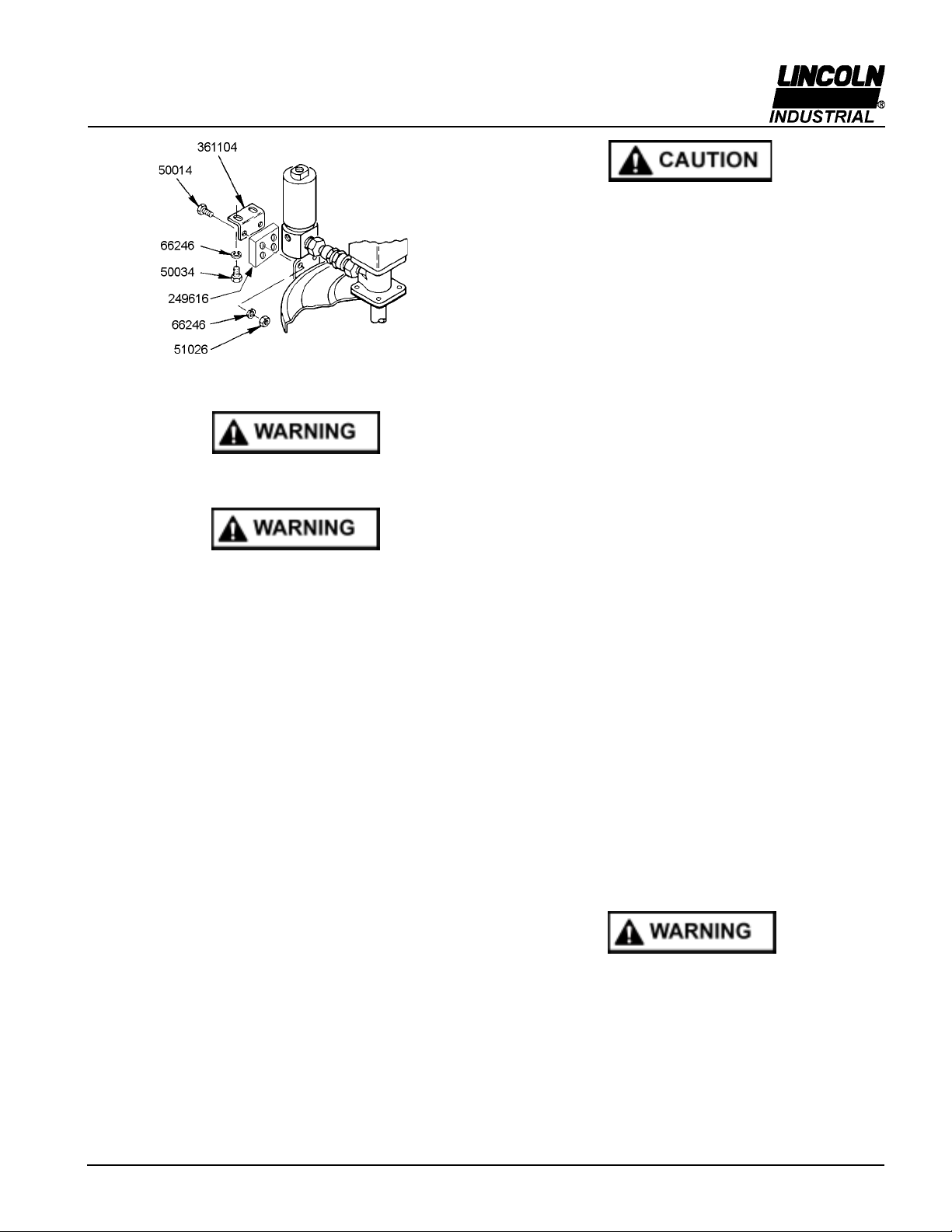
Disassem ly Procedure (See illustration #6)
Tools Required:
- Hex Bit Socket Wrenc es (3/8 square drive) wit 3/8 ex,
5/32 ex, 1/4 ex.
- 3/8 O.D. Steel Rod
- 12 Crescent Wrenc
- Spanner Wrenc (for 3/8 diameter tube, 1/8 pin)
- 1/2 to 3/8 square drive adapter
- Torque wrenc (1/2 square drive, 0 - 50 ft-lb capacity)
- Torque wrenc (3/8 square drive, 0 - 120 in-lb capacity)
- 1/4 nut driver
- Screwdriver (flat blade, 1/8 blade widt )
1. Remove t e four Socket Head Screws (33) and separate
Manifold from t e Hydraulic Motor (42).
2. Remove Pipe Plug (45) and drain t e crankcase oil from
t e Pump Housing (46).
3. Remove six self-t reading Screws (29) and remove t e
Housing Cover (30) and t e Cover Gasket (31).
4. Remove Retaining Ring (57) and pull t e S ovel Plug
(56) from t e Housing Tube (55).
5. Remove two Socket Head Screws (44) and separate t e
Hydraulic Motor (42) from t e Pump Housing (46).
6. Remove two Outlet Pin Nuts (50) from t e Pump Housing
(46).
7. Remove t e Pump Subassembly (1 t roug 28) from
t e Pump Housing (46). Pus ing t e subassembly up
wit a wooden or plastic rod 3/4 O.D. against t e C eck
Seat Housing (28) is elpful.
8. Remove t e Housing Tube (55) from t e Pump Housing
(46) by inserting a 3/4 rod t roug t e inlet oles at t e
bottom of t e Housing Tube (55) and unscrewing it.
9. Remove t e Bronze Bearing (51), t e O-Ring (52), and
t e Backup Was er (53) from t e Housing Tube (55).
10. Remove t e Crankrod Assembly (1 t roug 8) from t e
pump by unscrewing t e Button Head Screws (12) and
t en pulling out t e Wrist Pin Bus ings (13).
11. Remove t e C eck Seat Housing (28) from t e
Reciprocating Tube (21). T ere is a 3/8 Allen Head
socket in t e t roat of t e C eck Seat Housing (28) to
facilitate removal.
12. Unscrew t e Wrist Pin Anc or (14) from t e
Reciprocating Tube (21) and pull t e Plunger Assembly
(9 t roug 20) from t e tube.
13. Using a 1/2 wooden or plastic rod, pus t e Cup Seal
(22) and t e Pump Cylinder (24) from t e Reciprocating
Tube (21).
14. Remove t e Pump Plunger (20) from t e Plunger Link
Rod (17). A spanner wrenc , w ic uses t e oles in
t e Pump Plunger, is required.
15. Unscrew t e Plunger Link Rod (17) from t e Plunger
Tube (11) and slide off t e Cup Seal (16), t e Backup
Was er (15) and t e Wrist Pin Anc or (14).
16. Unscrew t e Plunger Tube (11) from t e Outlet Pin (9).
17. To dismantle t e Crankrod Assembly (1 t roug 8),
remove Flat Head Screws (1) and t e Counter Weig ts
(2).
18. Remove t e Retaining Rings (6) and press t e Crank
Eccentric (7) out of t e Ball Bearing (8). Be sure to
support t e Ball Bearing (8) on t e inner race.
Pump Assem ly Procedure
1. W en t e pump is dissembled, it is recommended to
replace all seals and gaskets, w ic are included in t e
270663 repair kit.
2. In t e process of disassembly, examine t e following
components and replace if excessive wear is indicated:
Ball Bearing (8), Crank Eccentric (7), Crankrod (5), Wrist
Pin Bus ings (13), Plunger Tube (11), Pump Plunger and
Upper C eck Parts (20, 19 and 18), Pump Cylinder (24),
C eck Seat Housing and Lower C eck Ball (28 and 26),
upper Bronze Bus ing (51), Housing Tube (55), S ovel
Plug (56), and Reciprocating Tube (21).
3. Assembly Procedure is t e reverse of t e Disassembly
Procedure except for t e following:
4. Install parts (22) t roug (28) into t e Reciprocating Tube
(21) after t e plunger assembly (9 t roug 20) is installed.
5. Install t e Pump Subassembly (1 t roug 28) into t e
pump Housing (46) before tig tening t e Housing Tube
(55) to t e Pump Housing (46). Be sure t e Reciprocating
Tube (21) is inserted t roug bot bus ings before
tig tening t e Housing Tube (55).
6. Use loctite 242 (or similar product) medium strengt t read
lock on all torqued t readed connections. Extreme care
must be exercised to prevent excess compound from
flowing into critical areas suc as clearance fits and ball
c eck. Allow a minimum of 30 minutes cure time before
operating t e pump.
7. Torque Specifications:
A. Plunger Tube (11) to Outlet Pin (9) - 100 to 110 In.-Lbs.
B. Button Head Screws (12) to Wrist Pin Anc or (14) 100
to 110 In.-Lbs.
C. Plunger Tube (11) to Plunger Link Rod (17) - 100 to 110
In.-Lbs.
D. Plunger Link Rod (17) to Pump Plunger (20) - 100 to
110 In.-Lbs.
E. Flat Head Screws (1) to Counter Weig t (2) - 100 - 110
In.-Lbs.
F. Wrist Pin Anc or (14) to Reciprocating Tube (21) - 20 to
25 Ft.-Lbs.
G. C eck Seat Housing (28) to Reciprocating Tube (21) -
20 to 25 Ft.-Lbs.
H. Outlet Pin Nut (50) to Pump Housing (47) - 30 to 35 Ft.-
Lbs.
I. Housing Tube (55) to Pump ousing (47) - 20 to 25 Ft.-
Lbs.
8. For Models 85480, 85481, 85482, 85483 and 85247, fill
crankcase wit SAE 10W30 motor oil up to pipe plug (45)
before fastening ousing cover (30) and ousing gasket
(31). If pump will be used in very cold environments, use
Mobil Arrow HFA Low Temperature Oil. T is oil stays fluid
even at -70°F.
For Model 85610, fill crankcase wit lig tweig t Mobil Arrow
HFA Hydraulic Oil up to pipe plug (45) before fastening
ousing cover (30) and ousing gasket (31).
9)On 85586, replace inlet strainer (63).
© Indicates c ange
©
©

FlowMaster Rotary Driven Hydraulic Pump
Page Number - 7
7.5A-18100-G01
Form 403139
5.025
(128)
11.46
(291)
9.54
(242)
1
2
3
B
A
6
8
4
7
5
ø 1.25
(32)
2.25
(57)
1/4-20 THD 2.25
(57)
9.08
(231)
4.61
(117)
1. 1/4 NPTF Pump Outlets
2. SAE 4 Inlet Port
3. SAE 6 Tank Port
4. 1/4 NPTF Orifice fitting for
Vent Valve Port
5. Solenoid Valve
6. Pressure Reducing Valve
7. Flow Control Valve
8. Pressure Gauge
Illustration #5
3.125
(79)
1.5
(38)
© indicates c ange
Fill wit SAE
10W30 Motor Oil
for Pumps 85480,
85481, 85482,
85483 and
85247. Fill wit
lig t weig t Mobil
Arrow HFA
Hydraulic Oil for
Pump 85610.©
MODEL DIM "A" in (mm) DIM "B" in (mm
)
85480 27.50 (699) 38.56 (980)
85481 19.00 (483) 30.06 (764)
85482 34.00 (864) 44.94 (1142)
85483 13.69 (348) 24.75(629)
85247© 27.50 (699) 38.56 (980)
85586© 34.18 (868) 45.12 (1146)
85610© 34.00 (864) 45.06 (1145)

FlowMaster Rotary Driven Hydraulic Pump
Page Number - 8 7.5A-18100-G01 Form 403139
31
32
29
30
62
33
58
34
35
36
37 59
38
39
61
60
40 41
42
43
44 51
52
54
53
55
56
57
63
50
49
48
47
46
45
1
2
4
68
76
5
4
21
10
11
12
13
14
15
16
17
18
19
20
21
22
23
24
25
26
27
28
9
Illustration #6

FlowMaster Rotary Driven Hydraulic Pump
Page Number - 9
7.5A-18100-G01
Form 403139
Repair Parts List
(Common to all Models)
Repair Parts List
(Non-common items)
© indicates c ange
* Included in 270663 Soft Parts Kit.
** T is Model is imilar to 85482, except t at t e crankcse is
filled wit Mobil Arrow HFA Low Temperature Oil.
*** T e inlet strainer fits on all FlowMaster models.
**** T is model is similar to 85482, several internal parts
are made more robustly for longer life.
1. Includes Gasket (Item 41) and O-Rings (Item 40).
2. Includes Seal Kit (Item 58).
3. Includes Seal Kit (Item 59).
4. Includes Seal Kit (Item 60).
Item No. Qty Description All Models Item No. Qty Description All Models
1 2 FlatHead Screw 34 1 Solenoid Valve
(1/4 x1-3/4) 270635 Cartridge (Note #2) 270690
2 2 Counter Weight 272197 or 1 Solenoid Valve Cartridge 272112
4 2 Retaining Ring 270609 © with Manual Override Knob 271918
5 1 Crankrod 270665 35 1 Solenoid Valve
6 2 Retaining Ring 270608 Coil (24 VDC) 270691
7 1 Crank Eccentric 270666 36 1 Solenoid Connector 242209
8 1 Ball Bearing 270607 37 1 Manifold 270771
9 1 OutletPin 270670 38 1 Pressure Reducing
10 1 O-Ring (Nitrile) * Valve (Note #3) 270692
11 1 Plunger Tube 270667 39 1 Flow Control Valve
12 2 Button Head Screw (Note #4) 270693
(1/4 x1/2) 270634 40 2 O-Ring (Viton) *
13 2 WristPin Bushing 270668 41 1 MotorGasket *
14 1 WristPin Anchor 270669 42 1 Hydraulic Motor
15 1 Backup Washer * (Note #1) 270676
16 1 Cup Seal 43 2 Washer 48548
(Polyurethane) * 44 2 Socket Head
17 1 Plunger Link Rod See ChartBelow Screw (1/2 x1-1/4) 270658
18 1 Spring 270616 45 1 Pipe Plug (3/8 NPTF) 67417
19 1 Ball 66010 46 1 Pump Housing 270673
20 1 Pump Plunger 270671 47 2 Backup Ring (Polyurethane) *
21 1 Reciprocating Tube See ChartBelow 48 2 O-Ring (Polyurethane) *
22 1 Cup Seal 49 2 O-Ring (Nitrile) *
(Polyurethane) * 50 2 OutletPin Nut 270619
23 1 O-Ring 51 1 Bronze Bearing 270674
(Polyurethane) * 52 1 O-Ring (Polyurethane) *
24 1 Pump Cylinder 270672 53 1 Backup Washer *
25 1 Ball Cage 270675 54 1 O-Ring (Nitrile) *
26 1 Ball 66001 55 1 Housing Tube See ChartBelow
27 1 O-Ring (Nitrile) * 56 1 Shovel Plug 270707
28 1 Check Seat 270664 57 1 Retaining Ring 270705
29 6 Self-Threading 58 1 Seal Kit(Nitrile) 270687
Screw (8 x1/2) 270633 59 1 Seal Kit(Nitrile) 270688
30 1 Housing Cover 270629 60 1 Seal Kit(Nitrile) 270689
31 1 Cover Gasket 61 1 Orifice Fitting 270735
(Nitrile) * 62 6 Gasket 252986
32 1 PressureGauge 270768 63 1 InletStrainer 272180***
33 4 Socket Head Softparts Kit 270663
Screw (5/16 x1-1/4) 270680
Item Qty. Description Model Model Model Model Model Mode
l
No. 85480 85481 85482 85483 85586**** 85610*
*
17 1 Plunger LinkRod 270648 270614 270645 270641 270645 27064
5
21 1 Reciprocating Tube 270649 270617 270646 270642 272176 27064
6
55 1 Housing Tube 270659 270660 270661 270662 270661 27066
1
25 1 Ball Cage 270675 270675 270675 270675 272179 27067
5
38 1 Pressure Reducing Valve 270692 270692 270692 270692 272117 27069
2
39 1 Flow Control Valve 270693 270693 270693 270693 270197 27069
3

FlowMaster Rotary Driven Hydraulic Pump
Page Number - 10 7.5A-18100-G01 Form 403139
Lincoln Industrial
25 International Business Park
#01-68 German Centre
Singapore 609916
(+65) 562-7960
Lincoln Industrial
One Lincoln Way
St. Louis, MO 63120-1578
(+1) 314 679 4200
Lincoln GmbH
69190 Walldorf
Heinric -Hertz Strasse 2-8
(+49) 6227 33-0
© Copyrig t 2001
Printed in USA
Web site:
www.lincolnindustrial.com
Condition Possible Cause Corrective Action
Pump does notrun. No pressure on gauge (32):
- Closed Supplyline shutoffvalve. Open shut-offvalve.
- No power to solenoid valve (34). Correct electrical fault.
- FaultySolenoid (35). Replace solenoid (35).
- Pressure Reducing Valve (38) is ResetPressure Reducing Valve (38)
.
set too low.
- InsufficientHydraulic Fluid supply. Check hydraulic supplyfor proper
pressure and flow.
Pressure is shown on gauge (32):
- Closed Fluid outletline. Check outletline and clear
obstructions.
- Flow Control valve is fullyclosed. Readjustvalve to 3/4 turn open.
- Pump is stalled due to grease Check ventvalve in system.
backpressure.
Pump is seized or damaged. Dismantle the pump and repair
defective or seized component. See
disassemblyand assembly
procedure.
Pump speeds up or runs erratically. Low level of grease or reservoir Refill reservoir.
is empty
Follower plate is stuck and separated Check follower plate and container
from grease. for damage.
Pump piston or checks are worn. Disassemble the pump and repair.
Pump runs, butoutputis low. Insufficienthydraulic fluid supply. Check hydraulic supplyand adjust
flow using valve 39.
Inletpressure too low. Increase pressure using valve 38.
Faultyinlet(25,26, 27) or discharge Replace faultycomponents.
check valve (18,19, 20).
Weepage from housing cover 30. Cup seal (16)or O-Ring (48) wore out. Checkthe seals and replace if
necessary.
Pump becomes noisy. No crank case oil. Add crank case oil.Remove Pipe
Plug (45)from Pump Housing (46).
Oil level should be atthe bottom of
the Pipe Plug opening.For Models
85480,85481,85482,85483 and
85247Add 10W30 motor oil until
the crankcase is full.
For Model 85610,add lightweight
Mobil Arrow HFAHydraulic Oil until
the crankcase is full.
Worn wristpin bushing 13. Checkthe bushings and replace if
necessary.
Pump dies notbuild pressure. Foreign material holding lower Dismantle & clear check. Consider
check open. installing inlet screen 272180
before returning pump to service.
Troubleshooting
This manual suits for next models
6
Table of contents
Other Lincoln Electric Water Pump manuals
Popular Water Pump manuals by other brands

AMEC
AMEC FPER Installation and Maintenance

Anest Iwata
Anest Iwata ISP-250C Series instruction manual

Bo-Camp
Bo-Camp 3807177 user manual

Homa
Homa C240WF Original instruction manual

Grundfos
Grundfos Multilift M Series Installation and operating instructions

Grundfos
Grundfos CRIE Installation and operating instructions