English 5 English
Installation and Operator Instructions
Read this entire section before installation or operating the
machine.
Exploitation conditions
This machine can operate in harsh environments.
However, it is important to use the following simple
preventive measures that will ensure its long life and
reliable operation:
Do not place or operate this machine on a surface with
an incline higher than 15° from horizontal.
Do not use this machine for pipe thawing.
This machine must be located where there is free
circulation of clean air without restrictions for air
movement. Do not cover the machine with paper, cloth
or rags when switched on.
Dirt and dust that can be drawn into the machine
should be kept away from the item.
This machine has a protection rating of IP23. Keep it
dry when possible and do not place it on a wet ground
or in puddles.
Locate the machine away from a radio controlled
machinery. Normal operation may adversely affect the
operation of a nearby radio controlled machinery,
which may result in injury or equipment damage. Read
the section on electromagnetic compatibility in this
manual.
Do not operate in areas with an ambient temperature
greater than 40°C.
Duty cycle and Overheating
The duty cycle of a welding machine is the percentage of
time in a 10 minute cycle at which the welder can operate
the machine at rated welding current.
Example: 60% duty cycle:
Welding for 6 minutes. Break for 4 minutes.
Excessive extension of the duty cycle will cause the
thermal protection circuit to activate.
Minutes or decrease
Duty Cycle
Input Supply Connection
Check the input voltage, phase, and frequency of the
power source that will be connected to this wire feeder.
The allowable input voltage of the power source is
indicated on the rating plate of the wire feeder. Verify the
connection of grounding wires from the power source to
the input source.
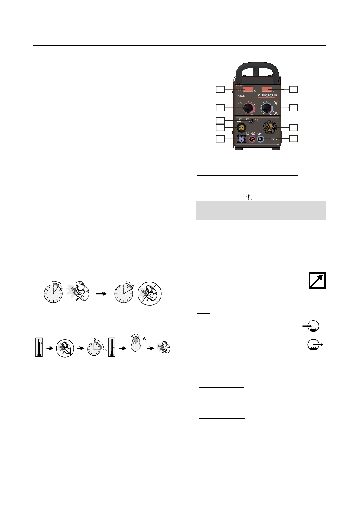
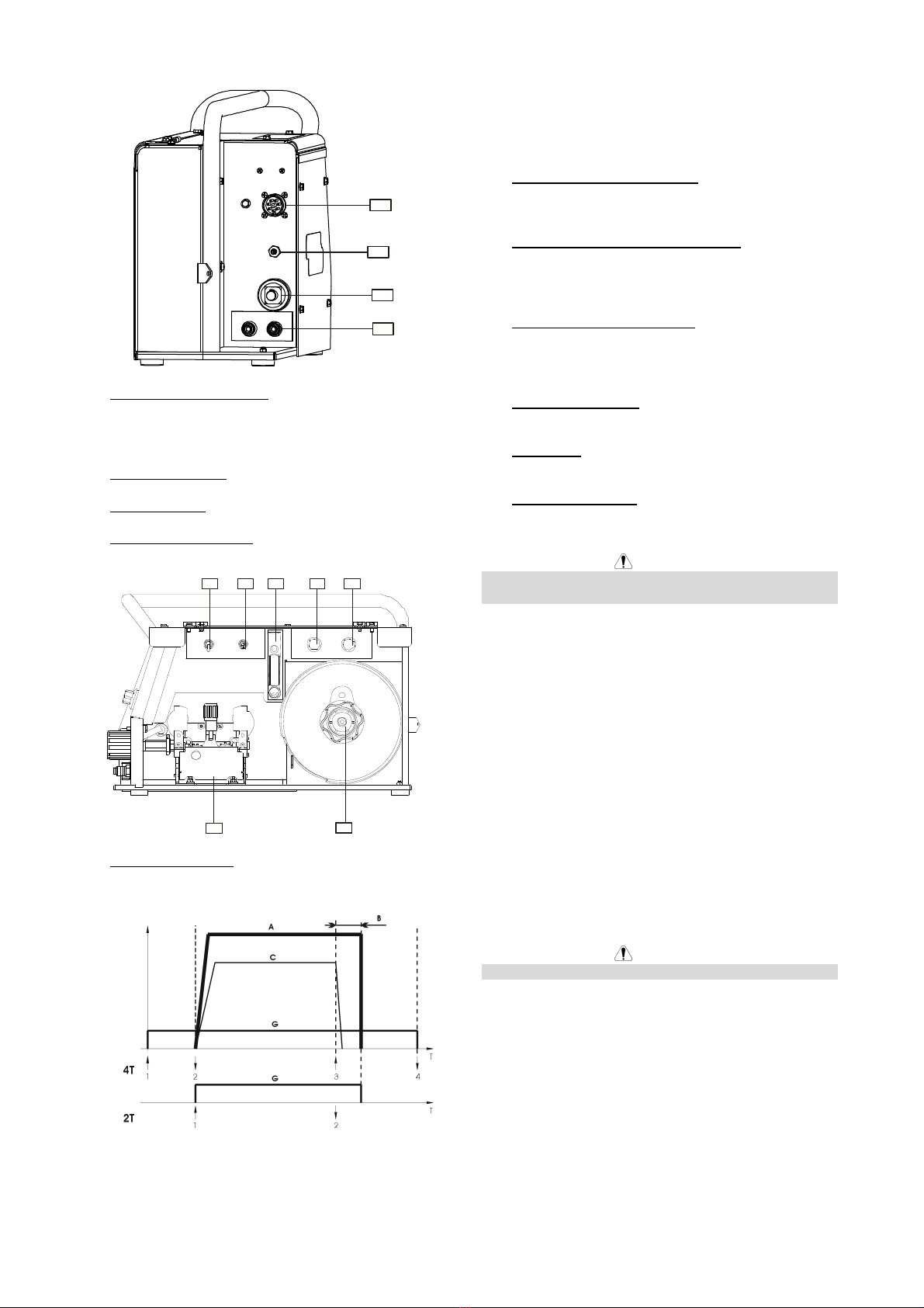
Controls and Operational Features
7
2
4
9
5
1
3
8
6
1. EURO Socket: or connecting welding torch.
2. WFS (Wire Feed Speed) Control Knob: It enables
continuous control of wire feeding speed in the range
from 1.0 to 20m/min.
WARNING
Before welding beginning and during Cold Inch Switch
using the Pro-welding Wire Speed Control Knob [16]
has also an influence on the wire feeding speed.
3. Output Voltage Control Knob: It enables continuous
control of welding voltage.
4. Local/Remote Switch: It changes the control of the
Output Voltage from the wire feeder Output Control
[3] to Remote Control Unit and vice versa.
5. Remote Control Receptacle: If a remote
control is used, it will be connected to the
remote receptacle (see Accessories for
ordering the desired unit).
6. Quick Connect Couplings (For water cooled model
only): For connecting water cooled torches.
Warm water from torch.
Cool water to torch.
7. Digital Display A: It shows the actual welding current
value (in A), and after finishing welding process, it
shows the average value of the welding current.
8. Digital Display V: It shows the actual value of
welding voltage (in V), and after finishing welding
process, it shows the average value of welding
voltage.
9. Fast-Mate Adapter: For connecting electrode touch.