Lincoln industrial 94804 User manual

Section
Page
-A50
Copyright 1999
Printed in U.S.A.
One Lincoln Way
St. Louis, Missouri 63120-1578
(314) 679-4200
Models 94804, 94806, 94808, 94810
4¼, 6, 8 & 10 IN. AIRMOTORS
WITH AIR BRAKE®
Series "A"
- 84E
SEP - 99 FORM 402911
OWNERS MANUAL
IT IS THE RESPONSIBILITY OF THE OWNER AND/OR OPERATOR TO PROPERLY USE AND MAINTAIN THIS
EQUIPMENT. CAREFULLY READ AND UNDERSTAND THE INSTRUCTIONS AND WARNINGS IN THIS MANUAL
BEFORE OPERATING THIS EQUIPMENT.
If the operator is not fluent in English, the instructions and warnings shall be read and discussed in the operators native language, making sure
the operator comprehends the contents.
This equipment complies with OSHA Standards where applicable.
This manual contains IMPORTANT WARNINGS and INSTRUCTIONS. READ AND RETAIN FOR REFERENCE.
DO NOT exceed the stated maximum working pressure of
the airmotor or of the lowest rated component in your system.
DO NOT alter or modify any part of this equipment.
DO NOT operate this equipment with combustible gas.
DO NOT attempt to repair or disassemble the equipment
while the system is pressurized.
TIGHTEN all fluid connections securely before using this
equipment.
ALWAYS read and follow the fluid manufacturers
recommendations regarding fluid compatibility, and the use
of protective clothing and equipment.
CHECK all equipment regularly and repair or replace worn or
damaged parts immediately.
IMPORTANT: Failure to heed these warnings including misuse,
overpressurizing, modifying parts, using incompatible
chemicals and fluids, or using worn or damaged parts, may
result in equipment damage and/or serious personal injury,
fire, explosion, or property damage.

PAGE 2 FORM 402911
02'(/
&</,1'(5
',$0(7(5
,100
())(&7,9(
3,6721
$5($,1ð
&0ð
23(5$7,1*
35(6685(
5$1*(36,*
%$5
23(5$7,1*
7(035$1*(
&)
0,1,'
2)$,5
6833/<
,100
$,5,1/(7
$,5&216#
36,*%$5
6&)&<&/(
/1&<&/(
137)
137)
137)
ó 137)
02'(/
0$;
5(&20
63(('
&30
6752.(
/(1*7+
,100
:(,*+7
/%.*
6($/6
0$7(5,$/
',0$
,100
',0%
,100
',0&
,100
%81$1
DQG
7()/21
SPECIFICATIONS
*TEFLON®Seals used with Power Valve Spool (Item 13) and Relay Valve (Item 17).

FORM 402911 PAGE 3
IMPORTANT: When replacing soft parts, replace all parts included in the soft parts kit.
SERVICE ASSEMBLIES & KITS
To reduce down-time and take advantage of the modular design of the airmotor, Lincoln recommends using the following Service
Assemblies for repair of the airmotor. After removal, the faulty assembly can then be repaired using the corresponding Soft Parts Kit.

PAGE 4 FORM 402911
NOTE: Refer to Page 3 for Service Assemblies & Kits

FORM 402911 PAGE 5
BEFORECONNECTING
AIRMOTOR TO AIR LINE
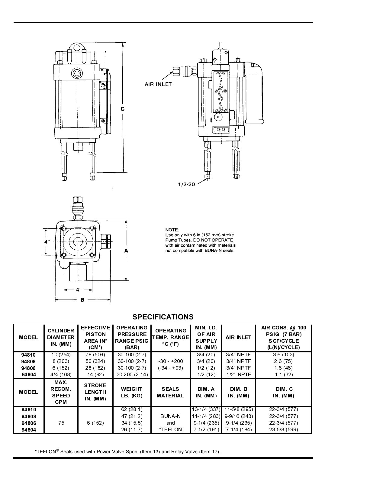
LINCOLN SERIES III AIRMOTORS are fully
pneumatic and require a minimum specified
size of air supply hose for proper operation.
Check specification for minimum ID. of the air
supply hose and select corresponding sizes
of air controls and accessories for non-
restrictive air flow. Lincoln filter, regulator
with gauge and lubricators are available as
combination units (FRL).
For 3/8 air line - Model 85387-6
For 1/2 air line - Model 85387-8
For 3/4 air line - Model 85387-12
If quick disconnect coupling should be used,
install supplied coupler to insure proper
airmotor operation.
NOTE: Whenever flammable materials are
pumped, ground Airmotor according to
Local Codes.
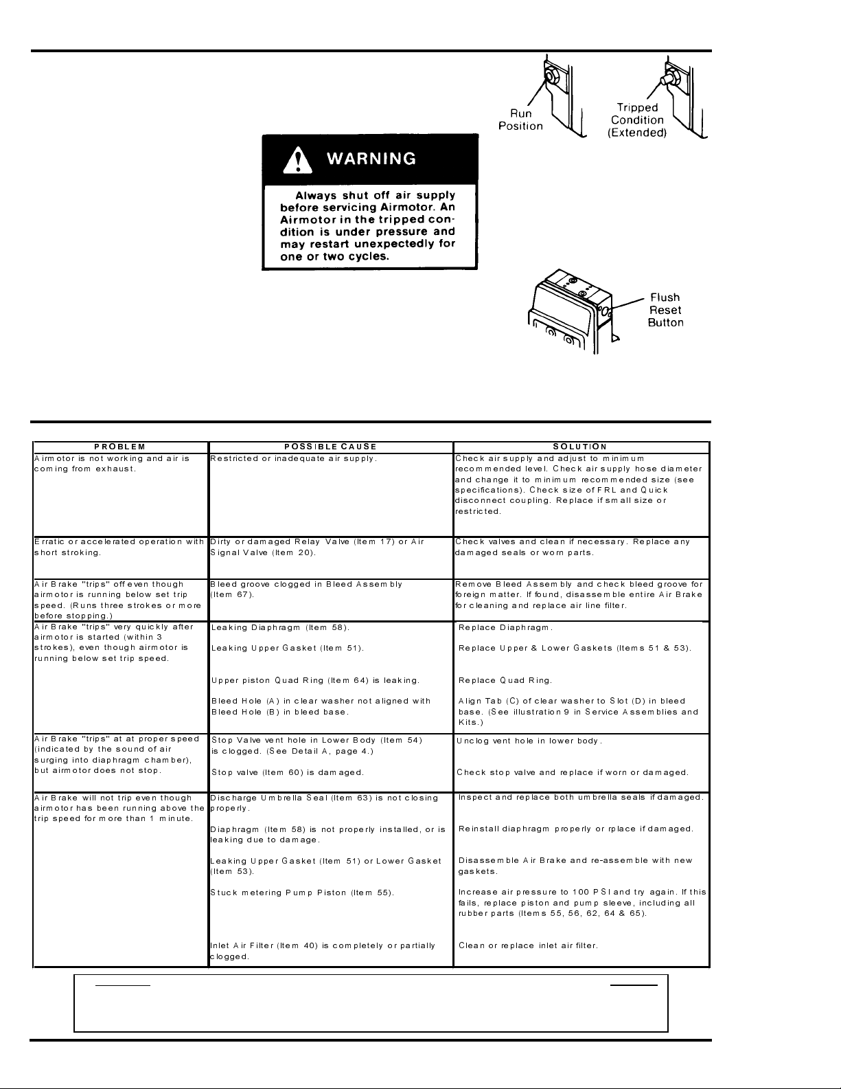
OPERATING PRECAUTIONS
Use Lincoln replacement parts to assure
compatible pressure rating.
Heed ALL warnings.
DO NOT OPERATE Airmotor in excess of
recommended pressure range.
Disconnect air line and relieve (vent)
pressure when Airmotor sits idle for long
periods of time and before servicing.
SERVICE AND DISASSEMBLY
PROCEDURE
ATTACHING AIRMOTOR TO
PUMPTUBE
1.Tightly attach the tie rods(ltem 41) to
the Airmotor lower casting. Use short
threaded end of tie rods.
2.Mount Airmotor on top of pump tube
outlet and tightly connect pump tube
coupling nut to Airmotor Piston Rod
(Item 5).
3.Hand tighten tie rods to the pump tube
with four nuts (Item 42) supplied with
Airmotor.
4.Connect air supply and slowly cycle
pump several times using only enough
air pressure to operate pump without
stalling.
5. STOP pump on "UP" stroke and tighten
four nuts to securely fasten Airmotor to
pump tube.
TOOLS REQUIRED
1. 7/64 (.109) Hex Wrench
2. 5/32 (.156) Hex Wrench
3. 3/16 (.189) Hex Wrench
4. 1/8 (.125) Hex Wrench
5. 3/4 (.750) Open End Wrench
(for 6 Airmotor)
6. 15/16 (.937) Open End Wrench
(for 8 Airmotor)
7. 1/2 (.500) Open End Wrench
(for 4-1/4 and 3 Airmotor)
8. 1-1/8 (1.125) Open End Wrench
(for 10 Airmotor)
9. 1/2" (.500) Box End Wrench
10. Pliers
11. 0-100 in. lb. Torque Wrench
The modular design of the Airmotor and
accessibility of vital operation parts make
service available without taking Airmotor out
of line or without complete disassembly.
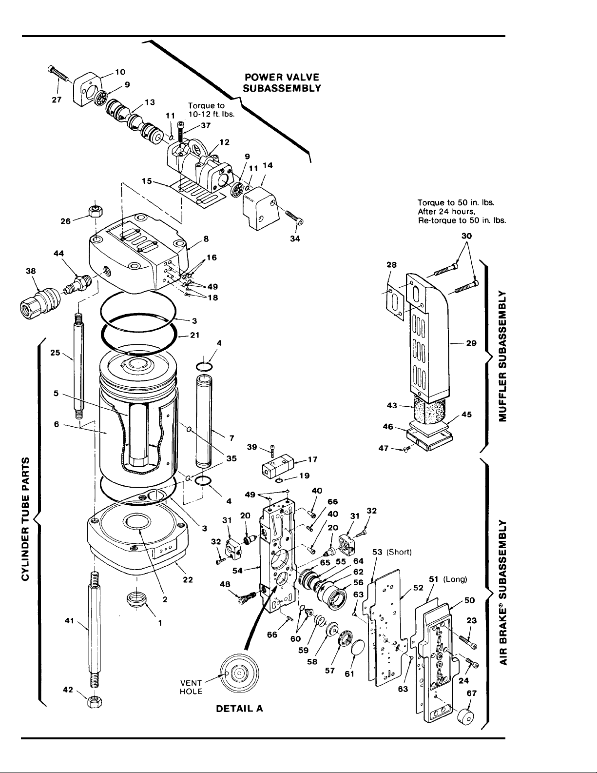
Power Valve
1. Remove four screws (Items 27 & 34)
with 3/16 hex wrench
(2 on each side).
2.Remove End Caps (Items 10 & 14).
3. Push out Valve Spool (Item 13).
4.Remove Spool Bumpers (Item 9)
(One from each end).
5.Remove O Ring (Item 11 )(One from
each end of valve body).
6.Remove four Screws (Item 37) with
3/16 hex wrench and lift valve body (Item
12).
7.Remove Gasket (Item 15) to complete
valve disassembly.
8.To REASSEMBLE, REVERSE procedure.
Cylinder Tube and Muffler
1. Remove Air Brakes Subassembly (See
previous instructions).
2. Remove two Screws (Item 30) with
3/16 hex wrench and pull off Mufler
(Item 29).
3. Remove Gasket (Items 28).
4. Remove four Nuts (Item 26) with open
end wrench.
5. Lift upward and remove Upper Casting
(Item 8).
6. Remove four Tie Rods (Item 25).
7. Remove Air Tube (Item 7).
8. Lift upward and remove Cylinder Tube
(Item 6).
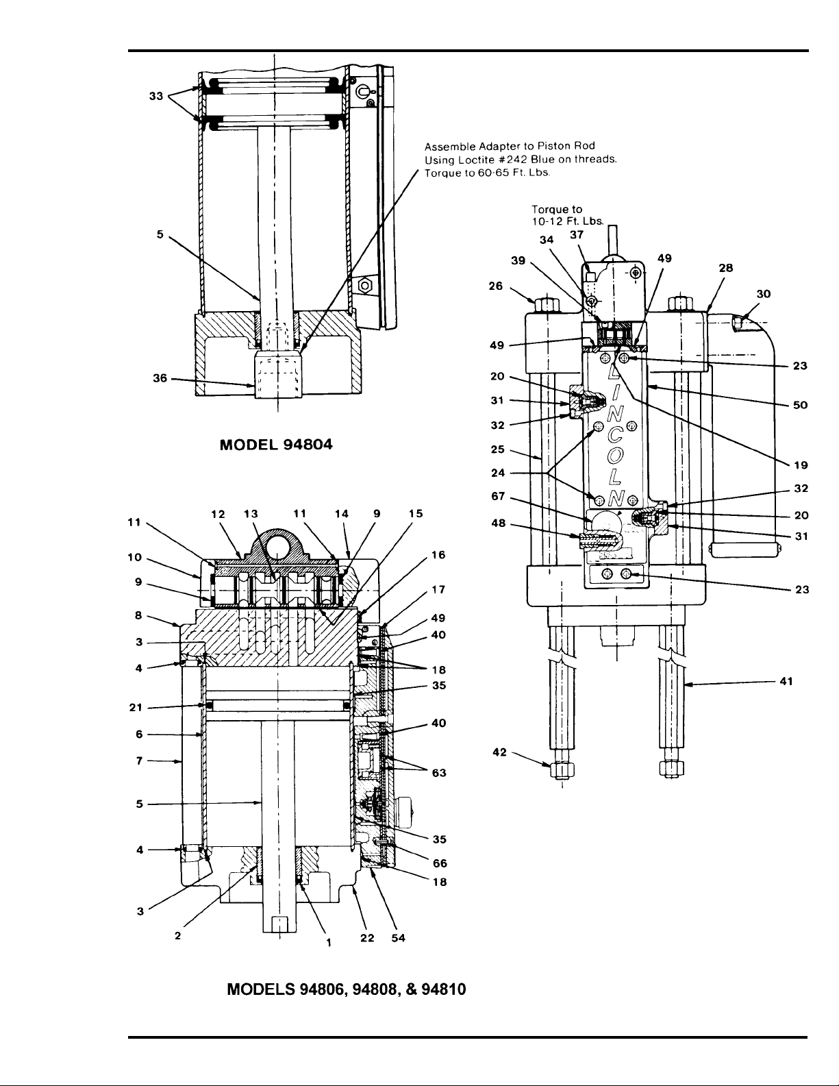
9. Remove Piston and Piston Rod (Item 5).
10. Remove four Connecting Rods (Item
41) with open end wrench.
11. To REASSEMBLE,REVERSE
procedure.
NOTE: Align two holes on the the Cylinder Tube (Item 6)
with two holes on the Air Brake®Subassembly before
tightening Tie Rods (Item 25) so that proper seal with
"0"-rings is acheived.
Air Brake®Subassembly
1. Remove four Screws (Item 23)(two on
each end) with 3/16" hex wrench and
pull out Air Brake® Subassembly.
2. Remove two Screws (Item 39), with
7/64" hex wrench and lift out Valve
Body (Item 17).
3. Remove four Screws (Item 32)(two on
each side of Air Brake®) with 1/8" hex
wrench and remove Signal Valve Caps
(Item 31) and Air Signal Valves (Item20).
4. Remove four Screws (Item 24) with
3/16 hex wrench and lift off Upper
Body (Item 50) and Upper Gasket
(Item 51).
5. Remove Gasket Plate (Item 52) and
Lower Gasket (Item 53).
6. Remove Air Filter (Item 40) in two
locations.
7. Remove Pump Sleeve (Item 56) and
Piston (Item 55).
8. Remove Diaphragm Seal and Retainer,
Diaphragm, Spring and Stop Valve Assy.
(Items 61, 57, 58, 59 & 60).
9. Remove cover from Bleed Assembly
(Item 67) and remove lock screw. Using
1/2 box end wrench, remove bleed
valve bolt and remaining parts.
10. Remove Trip Indicator (Item 48).
11.ToREASSEMBLE, REVERSE
procedure, insuring that:
a. Upper and Lower Gaskets (Items 51
& 53) are well oiled with 10 wt. motor oil.
b. Assembly Screws (Items 23 & 24) are
torqued to 65 to 70 in. lbs.

PAGE 6 FORM 402911
PARTS LIST
,WH P 1R 'H VFULSWLRQ 4 W\
0 RGH O
'LD
0 RGHO
'LD
0 RGH O
'LD
0 RGH O
ó 'LD
8&XS%XQD1 1RWH 1RWH 1RWH 1RWH
5RG%HDULQJ
6HDO&\OLQGHU%XQD1 1RWH 1RWH 1RWH 1RWH
2 ULQJ% XQD1 1RWH 1 RWH 1RWH 1RWH
3LVWRQ5RG$VVHP EO\
&\OLQGHU7XEH
$LU7XEH
8SSHU&DVWLQJ
%XP SHU9DOYH 1RWH 1RWH 1RWH 1RWH
&DS9DOYH
2ULQJ%XQD1 1RWH 1RWH 1RWH 1RWH
%RG\9DOYH 1RWH 1RWH 1RWH 1RWH
6SRRO9DOYH 1RWH 1RWH 1RWH 1RWH
&DS9DOYH
*DVNHW 1RWH 1RWH 1RWH 1RWH
2ULQJ%XQD1 1RWH 1RWH 1RWH 1RWH
5HOD\9DOYH
2ULQJ%XQD1 1RWH 1RWH 1RWH 1RWH
$LU6LJQDO9DOYH
2 ULQJ3 LVWRQ% XQD1 1RWH 1 RWH 1RWH
/RZHU&DVWLQJ
6 FUHZó [ò
6 FUHZó [
7LH5RG
1XW
6FUHZ
*DVNHW 1RWH 1RWH 1RWH 1RWH
0 XIIOHU%RG\
6 FUHZó [ò
6LJQDO9DOYH&DS 1RWH 1RWH 1RWH 1RWH
6FUHZ 1RWH 1RWH 1RWH 1RWH
6 HDO3 LV WRQ 1 RWH
6FUHZ
2ULQJ%XQD1 1RWH 1RWH 1RWH 1RWH
$ GDSWHU
6 FUHZó [ó
&RXSOHU
6FUHZ
$LU)LOWHU 1RWH 1RWH 1RWH 1RWH
7LH5RG
1XWò
0XIIOHU(OHPHQW 1RWH 1RWH 1RWH 1RWH
1LSSOH
( QG( OHP HQW 1RWH 1RWH 1RWH 1RWH
0 XIIOHU3ODWH
6FUHZ6HOI7DSSLQJ
7ULS,QGLFDWRU
2ULQJ%XQD1 1RWH 1RWH 1RWH 1RWH
8SSHU%RG\
8SSHU*DVNHW1LWULOH 1RWH 1RWH 1RWH 1RWH
* DVNHW3 ODWH 1RWH 1RWH 1RWH 1RWH
/RZHU*DVNHW1LWULOH 1RWH 1RWH 1RWH 1RWH
/RZHU%RG\ 1$ 1$ 1$ 1$
3LVWRQ 1RWH 1RWH 1RWH 1RWH
3 XP S6OHHYH 1RWH 1RWH 1RWH 1RWH
'LDSKUDJP 5HWDLQHU 1RWH 1RWH 1RWH 1RWH
'LDSKUDJP 1RWH 1RWH 1RWH 1RWH
6SULQJ 1RWH 1RWH 1RWH 1RWH
6WRS9DOYH$VVHP EO\ 1RWH 1RWH 1RWH 1RWH
'LDSKUDJP 6HDO 1RWH 1RWH 1RWH 1RWH
2ULQJ%XQD1 1RWH 1RWH 1RWH 1RWH
8P EUHOOD6HDO1LWULOH 1RWH 1RWH 1RWH 1RWH
4XDG5LQJ%XQD1 1RWH 1RWH 1RWH 1RWH
6SULQJ3LQ
% OHHG$VVHP EO\
NOTES: 1. Included in 84791 Cylinder Tube Soft Parts Kit for 7. Included in 244089 Gasket and Air Filter Kit.
Model 94808 (8" Airmotor). 8. Included in 243853 Signal Valve Cap Kit.
2. Included in 84792 Cylinder Tube Soft Parts Kit for 9. Included in 244093 Gasket Plate with Check
Model 94806 (6" Airmotor). Valves.
3. Included in 84793 Cylinder Tube Soft Parts Kit for 10. Included in 244092 Air Pump Repair Kit.
Model 94804 (4¼" Airmotor). 11. Included in 244091 Stop Valve Repair Kit.
4. Included in 84939 Muffler Element Kit. 12. Included in 84789 Cylinder Tube Soft Parts Kit for
5. Included in 84968 Soft Parts Kit for Power Valve Model 94810 (10" Airmotor).
Subassembly. 13. Included in 244802 Power Valve & Spool Body.
6. Included in 84967 Soft Parts Kit for Air Brake®
Subassembly.
N/A - Not Available

FORM 402911 PAGE 7

PAGE 8 FORM 402911
TROUBLESHOOTING
RETAIN THIS INFORMATION FOR FUTURE REFERENCE
When ordering replacement parts, list: Part Number, Description, Model Number and Series Letter.
LINCOLN provides a Distributor Network that stocks equipment and replacement parts.
SETTING THE AIR BRAKE®TRIP
SPEED
1. Determine the maximum speed
the Airmotor will need to run.
2. Add 15 cycles per minute to this
maximum required speed.
3. Loosen the lock screw.
4. Rotate the bleed knob to the correct
setting as follows:
Maximum
Airmotor Bleed Knob
Speed Setting
0-20 cycles/min. Low
20-50 cycles/min. Medium
50-75 cycles/min. High
5. Turn lock screw until it contacts spring
washer, then tighten additional 1/2" turn.
6.Test unit in normal use to insure setting
is not too low. If Air Brake®stops
Airmotor during normal operation,
increase the setting.
AIR BRAKE®RESETTING
INSTRUCTIONS
If the Airmotor runs faster than the preset
speed, the Air Brake®will stop the air
motor with the pump plunger in the down
position. The Trip Indicator piston extends
to indicate that the Air Brake® has been
triggered and is preventing Airmotor
operation.
NOTE: Air Brake®is disabled when
bleed knob is set on the run
setting.
To reset the Air Brake®:
1. Shut off air supply to Airmotor.
2. Press flush reset button with a
screwdriver (located on right side of
Relay Valve - Item 17) until Air Brake®
shifts and indicator button retracts.
3. Wait two full minutes to insure all
residual pressure vents off.
4. Turn on air supply. Airmotor will now
restart.
352%/(0 3266,%/(&$86( 62/87,21
$LUP RWRULVQRWZRUNLQJDQGDLULV
FRP LQJIURPH[KDXVW
5HVWULFWHGRULQDGHTXDWHDLUVXSSO\ &KHFNDLUVXSSO\DQGDGMXVWWRPLQLPXP
UHFRP PHQGHGOHYHO&KHFNDLUVXSSO\KRVHGLDPHWHU
DQGFKDQJHLWWRP LQLPXPUHFRPPHQGHGVL]HVHH
VSHFLILFDWLRQV&KHFNVL]HRI)5/DQG4XLFN
GLVFRQQHFWFRXSOLQJ5HSODFHLIVPDOOVL]HRU
UHVWULFWHG
(UUDWLFRUDFFHOHUDWHGRSHUDWLRQZLWK
VKRUWVWURNLQJ
'LUW\RUGDPDJHG5HOD\9DOYH,WHPRU$LU
6 LJQDO9 DOYH,WHP
&KHFNYDOYHVDQGFOHDQLIQHFHVVDU\5HSODFHDQ\
GDPDJHGVHDOVRUZRUQSDUWV
$LU%UDNHWULSVRIIHYHQWKRXJK
DLUP RWRULVUXQQLQJEHORZVHWWULS
VSHHG5XQVWKUHHVWURNHVRUPRUH
EHIRUHVWRSSLQJ
%OHHGJURRYHFORJJHGLQ%OHHG$VVHP EO\
,WHP
5HP RYH%OHHG$VVHPEO\DQGFKHFNEOHHGJURRYHIRU
IRUHLJQPDWWHU,IIRXQGGLVDVVHPEOHHQWLUH$LU%UDNH
IRUFOHDQLQJDQGUHSODFHDLUOLQHILOWHU
$LU%UDNHWULSVYHU\TXLFNO\DIWHU
DLUP RWRULVVWDUWHGZLWKLQ
VWURNHVHYHQWKRXJKDLUP RWRULV
UXQQLQJEHORZVHWWULSVSHHG
$LU%UDNHWULSVDWDWSURSHUVSHHG
LQGLFDWHGE\WKHVRXQGRIDLU
VXUJLQJLQWRGLDSKUDJPFKDPEHU
EXWDLUPRWRUGRHVQRWVWRS
$LU%UDNHZLOOQRWWULSHYHQWKRXJK
DLUP RWRU
KDV
EHHQ
UXQQLQJ
DERYH
WKH
WULSVSHHGIRUP RUHWKDQP LQXWH
/HDNLQJ'LDSKUDJP,WHP
/HDNLQJ8SSHU*DVNHW,WHP
8SSHUSLVWRQ4XDG5LQJ,WHPLVOHDNLQJ
%OHHG+ROH$LQFOHDUZDVKHUQRWDOLJQHGZLWK
%OHHG+ROH%LQEOHHGEDVH
5HSODFH'LDSKUDJP
5HSODFH8SSHU/RZHU*DVNHWV,WHPV
5HSODFH4XDG5LQJ
$OLJQ7DE&RIFOHDUZDVKHUWR6ORW'LQEOHHG
EDVH
6HH
LOOXVWUDWLRQ
LQ
6HUYLFH
$ VV HP EOLHV
DQG
.LWV
6WRS9DOYHYHQWKROHLQ/RZHU%RG\,WHP
LVFORJJHG6HH'HWDLO$SDJH
6WRSYDOYH,WHPLVGDPDJHG
8QFORJYHQWKROHLQORZHUERG\
&KHFNVWRSYDOYHDQGUHSODFHLIZRUQRUGDPDJHG
'LVFKDUJH8PEUHOOD6HDO,WHPLVQRWFORVLQJ
SURSHUO\
'LDSKUDJP
,WHP
LV
QRW
SURSHUO\
LQVWDOOHG
RU
LV
OHDNLQJGXHWRGDPDJH
/HDNLQJ8SSHU*DVNHW,WHPRU/RZHU*DVNHW
,WHP
6WXFNPHWHULQJ3XPS3LVWRQ,WHP
,QOHW$LU)LOWHU,WHP LVFRP SOHWHO\ RUSDUWLDOO\
FORJJHG
,QVSHFWDQGUHSODFHERWKXPEUHOODVHDOVLIGDPDJHG
5HLQVWDOOGLDSKUDJPSURSHUO\RUUSODFHLIGDPDJHG
'LVDVVHPEOH$LU%UDNHDQGUHDVVHPEOHZLWKQHZ
JDVNHWV
,QFUHDVH
DLU
SUHVVXUH
WR
36,
DQG
WU\
DJDLQ
,I
WKLV
IDLOVUHSODFHSLVWRQDQGSXPSVOHHYHLQFOXGLQJDOO
UXEEHUSDUWV,WHPV
&OHDQRUUHSODFHLQOHWDLUILOWHU
This manual suits for next models
3
Popular Engine manuals by other brands

Motorola
Motorola c18 Developer's guide

Mitsubishi Electric
Mitsubishi Electric MELSERVO-J5-HK-KT Series user manual

Simple Motors
Simple Motors Kit 2 Assembly instructions

Kohler
Kohler 37108B owner's manual

Stihl
Stihl TS 460 Service manual

Singer
Singer BUK Electric Motor Instructions for using and adjusting