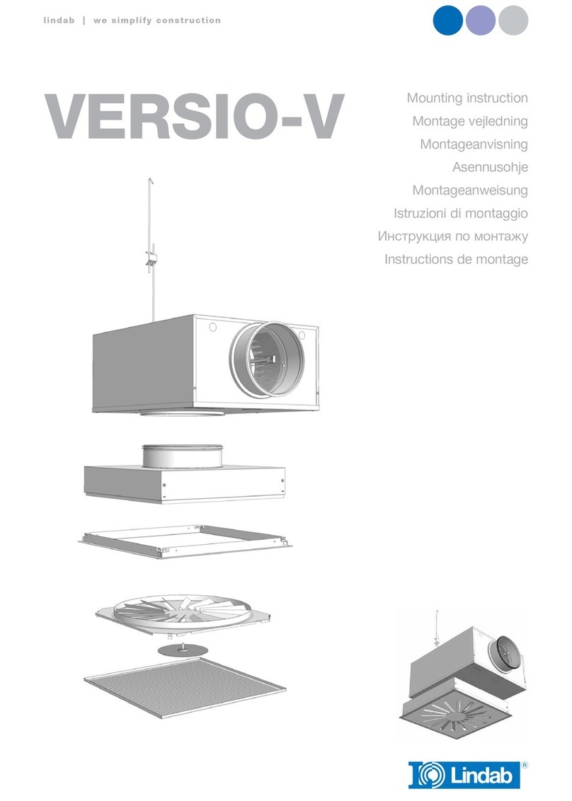
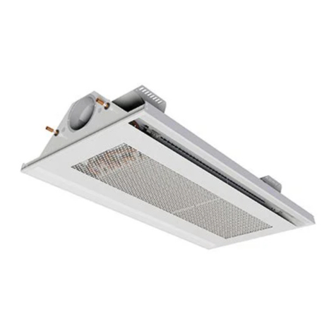
Lindab Fasadium Installation and user guide

© 2022.09 Lindab Ventilation. All forms of reproduction without written permission are forbidden. is the registered trademark of Lindab AB.
Lindab's products, systems, product and product group designations are protected by intellectual property rights (IPR).
lindab | for a better climate
LindabFasadium
Service & Maintenance

2
Service & Maintenance Fasadium
Lindab reserves the right to make changes without prior notice
2022-09-30
Lindab reserves the right to make changes without prior notice
2022-09-30
lindab | for a better climate
1.0 Installation
1.1 Product description
Lindab’s facade system Fasadium is an efficient system designed for ventilation,
cooling and heating from the facade. Typical environments where Fasadium is used
include, for example, schools, hospitals and offices. The Fasadium unit is placed at
the building façade, preferably under a window sill.
1.2 Handling
The beam must be handled with care, ensuring that the beam does not sustain
dents, scratches or bends during installation.
Always seek to lift the beam at multiple points.
– Do not lift in pipes.
– Do not lift in edges.
– Each beam is equipped with protective film to avoid any damage during trans-
port and handling at building site. The film needs to be removed before com-
missioning the products.
1.3 Mounting instruction
– Please visit www.lindQST.com
• Select Documentation Finder
• Select “Fasadium”
• Select “Mounting”
1.4 Air connection installation
The primary air supply should be connected with instructions from a ventilation
specialist. Lindab’s chilled beams can beneficially be used together with Lindab’s
Safe® duct systems.
1.5 Connection description water
Flow indication arrows are shown on the inlet and return pipes in order to assist
the installer.
If the control valves have been ordered separately, a special direction of the flow
must be upheld to ensure correct flow through the control valve. Please note the
flow direction indicator on the valve to insure correct installation in relation to the
desired flow.
When connecting a panel or a beam with the piping system either a push-on fitting
or a compression coupling should be used. Lindab have tested and recommends
John Guest push on fittings as well as push-on fittings from Tectite (available as
accessory. See Accessories).
To avoid sound being transported over the beam, we recommend to use our
flexible hoses between the piping and the beam connections. See Accessories.
NB! Every control valve can create sound when it is installed directly connected
to the water in- or outlet (or into the piping in close distance to the in- or outlet
of the water product). To avoid unwanted sound generation we recommend to
always use a Lindab control valve LinFlow-A (angled) or LinFlow-S (straight) and
calculate the beam with the valve in LindQST\waterborne calculator.

3
Service & Maintenance Fasadium
Lindab reserves the right to make changes without prior notice
2022-09-30
lindab | for a better climate
1.5.1 Before installation
Notice! The connection pipes are internally soft-welded, therefore it is not allowed
to solder the beam to the pipes. For other than Lindab fittings and valves, please
consult the installation guide for the specific fitting for further details on proper
installation.
Both inlet- and return pipes are covered by a plastic or rubber protection cover,
which must be removed before installation.
After removing the protection cover, make sure that the pipe is intact and unda-
maged, especially at the pipe end, as even small dents and scratches potentially
pose a risk of leakage in the system.
Eventually deburr the pipe ends on the inside and the outside, using a deburring
tool before installation.
Always remember to do a pressure test after assembly of the pipe work.

4
Lmin*
Service & Maintenance Fasadium
Lindab reserves the right to make changes without prior notice
2022-09-30
Lindab reserves the right to make changes without prior notice
2022-09-30
lindab | for a better climate
1.5.2 Push-on valve
Mount a push-on valve to the pipe. Make sure the valve has the correct flow direc-
tion (see indication arrow on the valve) and that you have the correct valve, when
integrated valve has been chosen (see indication on valve or follow cabelling to
Regula Connect card). Cooper inserts aren't required !
Please refer to the suppliers manual.
1.5.3 Compression fitting
While mounting a compression fitting, the pipe will be exposed to a big amount of
force, creating a risk of crushing the pipe. To ensure that the pipe won’t be crus-
hed when mounting the compression fitting, a copper insert must be inserted into
the pipe (always part of the delivery).
The copper insert should be placed inside the pipe on the beam. Always support
the copper pipe coil when inserting the copper insert into position.
Mount a compression coupling and/or a valve to the pipe. Don’t stress the nut too
much, since this may crush the pipe.
Please refer to the suppliers manual.
1.5.4 Flexible hoses
Our flexible hoses with straight ends can be used with both push-on and
compres-sion fitting.
We recommend to use our flexible hoses with push-on fittings, for easier and
faster mounting.
For the connection to an enclosed valve with integrated push on coupling a flex-
ible hose with straight end (male) or with push on (female) and a short copper pipe
can be used.
Please refer to the suppliers manual.
* Lmin = 70 mm (to ensure you can open the couplings again).
Lindab flexible hoses are available with straight end (male) for direct connection to Lindab valves also.

5
Order : xx-xxxxx
Project : xxxxxx xxxxxxxx
Mark : xxxxx
Nozzles : N/A
Product ID : xxxxxxx
Plugs : N/A Sign. :
Pos : xx
Munio-I-xxx-12-125-AX
Pressure: AA Pa Flow: BB l/s
x,xx m
Fasadium: x-x-xx-xx-xxx-Xx
xx
xx xx xx
xx
xx
xx-xx
Service & Maintenance Fasadium
Lindab reserves the right to make changes without prior notice
2022-09-30
lindab | for a better climate
2.0 Commissioning
2.1 Product labeling
– Read off the static nozzle pressure from the manometer
Fig.1: Label location exterior (water connection)
On the label you’ll find:
– Order: Order identification number.
– Pos: Order position.
– Product: Product configuration.
– Project: Project name.
– Mark: Marking noted on order.
– Nozzles: Number of nozzles.
– Plugs: Number of plugged nozzles.
– Product ID: Product number.
– Sign: To be signed when checked and commissioned on site.
2.2 Measure air pressure and calculating the airflow.
Before calculating the airflow, the static nozzle pressure must first be measured.
The static nozzle pressure is the air pressure available at the nozzles.
2.2.1 Measure the static nozzle pressure.
– To measure the air pressure, a manometer, analog or digital (such as the Lindab
PC410) will be needed.
– Insert the measuring tube into any of the nozzles.

6
Pressure
[Pa]
Air flow [l/s]
300
10 12 14 16 18 20
22
24
26
30
32
34
36
38
40 45 50 55 60 65
28
200
100
150
90
80
70
60
50
4 5 6 7 8 9 10 15 20 25 30 35 40 45 50 60 70 80 90 100
Number open Nozzles
Service & Maintenance Fasadium
Lindab reserves the right to make changes without prior notice
2022-09-30
Lindab reserves the right to make changes without prior notice
2022-09-30
lindab | for a better climate
2.2.2 Calculating the airflow
– After measuring the static nozzle pressure, calculate the air flow per nozzle:
q=0.0622∙√P
q = air flow per nozzle
P = static nozzle pressure
– After finding the air flow per nozzle, find the needed number of open nozzles:
q tot/q=n open
q tot = total air flow
n open = open nozzles
– Alternatively, read off the needed number of nozzles in the diagram below.

7
Service & Maintenance Fasadium
Lindab reserves the right to make changes without prior notice
2022-09-30
lindab | for a better climate
3.0 Maintenance
The interval of cleaning depends on the indoor environment where the beam is
pladed.
Under optimal conditions the Fasadium beams only need cleaning every 5 years.
3.1 Cleaning instructions
– Remove the battery ocver plate.
– Clean underneath the battery and inside the air dispersal duct with a vacuum
cleaner and a piece of wet cloth.
– Only use lukewarm water and a mild detergent.
2.3 Changing the airflow
– Measure the static nozzle pressure.
– Calculate the needed number of nozzles to be plugged, in order to reach the
desired airflow at the available air pressure, as see the diagram above.
– Plug or unplug nozzles to reach the desired air flow. Using the Lindab Fasa-
dium plug-tool.
– Dividing the plugs evenly, will result in an even air spread.

8
Service & Maintenance Fasadium
Lindab reserves the right to make changes without prior notice
2022-09-30
Lindab reserves the right to make changes without prior notice
2022-09-30
lindab | for a better climate
4.0 Product and system specification
4.1 Material data
Fasadium
600
Fasadium
700
Fasadium
800
Fasadium
1000
Fasadium
1200
Fasadium
1500
Dry weight, kg/m, Ø100 duct 6.6 7.5 8.5 11.3 13.7 17.0
Dry weight, kg/m, Ø160 duct 7.0 8.0 9.0 12.0 14.5 18.0
Dry weight, kg/m, Ø200 duct 7.6 8.5 9.5 12.7 15.3 19.0
Water content, cooling, l. 0.57 0.17 0.83 1.15 1.42 1.83
Water content, heating, l. 0.13 0.16 0.18 0.10 0.13 0.16
Copper pipes, quality EN 12735-2
CU-DHP
Pressure class PN10
4.2 Environmental declaration
Please follow the links below
• Building product declaration
• Declaration of conformity
• Eurovent certificate
4.3 Pressure class
The waterborne products in Lindab, active chilled beams (battery products), passive
chilled beams (battery and strips products), facade units (battery) and radiant panels
(strips and panels) are produced according to pressure class PN10 according to EN
1333: 2006.
This means the maximal working pressure for the products at a water temperature of
20°C must not exceed 10 bar.
4.4 Water quality
Lindab recommend water treatment and quality to be according to VDI 2035-2.
– The water preparation and maintenance for the chilled beam water circuit
should be handled by a specialist.
– To prevent corrosion, the water circuit must be airtight.
– The water system must also be equipped with aerators to remove any build-up
air in the system.

9
Service & Maintenance Fasadium
Lindab reserves the right to make changes without prior notice
2022-09-30
lindab | for a better climate
– The water should be oxygen free, to prevent corrosion.
– The water system must be filled with potable water that complies with the “EC
directive 98/83/EC”.
– pH value of water must be between approximately 6-9 pH.
– The water velocities should not exceed 1m/s, and should be kept as close to
the nominal flow as possible to minimize noise and optimize the energy yield.
– There should be used in-line strainers to remove dirt particles from the water.
– If the water contains any additive inhibitor this must be appropriate to use with
copper and solder.
4.5 Capacity test
– Lindabs active chilled beams are Eurovent-certified and tested according to
EN-15116.

www.lindab.comwww.lindab.com
Most of us spend the majority of our time indoors. In-
door climate is crucial to how we feel, how productive
we are and if we stay healthy.
We at Lindab have therefore made it our most important
objective to contribute to an indoor climate that improves
people’s lives. We do this by developing energy-efficient
ventilation solutions and durable building products. We
also aim to contribute to a better climate for our planet
by working in a way that is sustainable for both people
and the environment.
Lindab | For a better climate
For a better climate
Table of contents
Other Lindab Air Handler manuals
Popular Air Handler manuals by other brands

EQK
EQK 18S-EHVC WD2V Series troubleshooting manual

Trane
Trane 2/4TEC3F18B1000A Installer's guide

Allstyle
Allstyle EFM Series installation guide

AAON
AAON M3 Series Installation operation & maintenance

Vent-Axia
Vent-Axia Lo-Carbon PoziDry Pro 476310 Installation and wiring instructions

Airflow
Airflow Adroit DV50 instruction manual

OSTBERG
OSTBERG HERU SELECT Series manual

Exhausto
Exhausto VEX300 Series Mechanical assembly and electrical installation

Klimor
Klimor EVO-RX Operation and maintenance manual

EMI
EMI CAHV09 Installation, operation and maintenance manual

Amana
Amana AMVE Installation & operating instructions

BLAUBERG Ventilatoren
BLAUBERG Ventilatoren KOMFORT LE Series Operation manual