Linde Warnprojektor 45 User manual

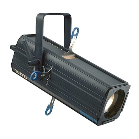
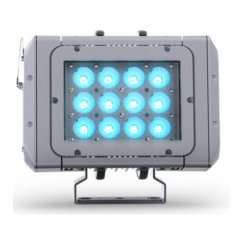
Linde warning projector
Original instructions
3008011680 EN – 06/2018


Table of contents
g
1 Introduction
Linde warning projector ............................................... 2
Symbols used ...................................................... 2
Contact details ...................................................... 3
2Overview
Component overview ................................................. 6
3 Assembly
Assembling the Linde warning projector ................................... 8
Projection size ...................................................... 9
4 Operation
Inserting or replacing the gobo .......................................... 12
Focusing the warning pictogram ......................................... 13
Aligning the warning pictogram .......................................... 13
5 Technical data
Dimensions ........................................................ 16
Technical data ...................................................... 16
Operating Instructions – 3008011680 EN – 06/2018 I


1
Introduction

1Introduction
Linde warning projector
Description of use
The Linde warning projector is a compact
high-power LED spotlight for projecting
warning pictograms.
The projection of warning pictograms ensures
clear and permanent visibility and thus aids
the perception of dangers. The warnings are
permanently visible, regardless of wear and
dirt. Maintenance costs are reduced. Safety
is increased.
Warning pictograms are also clearly visible in
working environments with low light levels.
A selection of "gobos" (graphical optical
blackouts) can be used with the projector,
allowing individual adaptation to the ambient
conditions and the particular application.
To further increase occupational health and
safety, the Linde warning projector can be
combined with the Linde Safety Guard static
warning unit. The warning projector can
thereby be switched on when an industrial
truck approaches.
Intended use
The Linde warning projector is used solely to
project warning pictograms.
The warning projector is suitable for indoor use
in industrial environments. It can be mounted
on the ceiling, on walls or onstruts.
The projections do not exempt the drivers of
industrial trucks and pedestrians from their
legal duty of care to avoid any potentially
dangerous situations.
WARNING
Damage to eyes!
Do not look directly into the Linde
warning projector.
The Linde warning projector is assigned to risk
group 2 in accordance with DIN EN 62471.
Symbols used
DANGER
Failure to comply can result in fatal injuries and/or
major damage to equipment.
WARNING
Failuretocom
ply can result in serious injuries
and/or major damage to equipment.
CAUTION
Failure to comply can result in damage to or de-
struction of the material.
NOTE
Explanation of technical context that may not
be evident eventoaspecialist.
2 Operating Instructions – 3008011680 EN – 06/2018
Introduction 1
Contact details
Contact details
Manufacturer
Derksen Lichttechnik GmbH
Johannes-Rau-Allee 4
45889 Gelsenkirchen, Germany
Telephone: +49 (0) 209 98070-0
Fax: +49 (0) 209 98070-60
Email: [email protected]
Website: https://www.derksen.de/en/
Sales and service by:
Linde Material Handling GmbH
Carl-von-Linde-Platz
63743 Aschaffenburg, Germany
Telephone: +49 (0) 6021 99-0
Fax: +49 (0) 6021 99-1570
Email: [email protected]
Website: http://www.linde-mh.de
Operating Instructions – 3008011680 EN – 06/2018 3

1Introduction
Contact details
4 Operating Instructions – 3008011680 EN – 06/2018

2
Overview

2Overview
Component overview
Component overview
LWP_13
1
2
9
3
5
6
8
7
4
1 Housing
2 Sleeve
3 Projector head
4 Sealing ring
5 Gobo holder
6 Lens holder
7 Lens
8 Mounting plate
9 Bush for power supply
6 Operating Instructions – 3008011680 EN – 06/2018
3
Assembly

3Assembly
Assembling the Linde warning projector
LWP_03
1
3
2
1 Socket head screw M6x20 mm
2 Spring washer M6
3 Mounting plate
Assembling the Linde warning
projector
WARNING
Risk of injury due to insecure mounting.
Mount the warning projector on constructions
that can bear four times the weight of the device.
Use suitable mounting material.
Unscrew four screws (1) along with spring
washers (2) and release the mounting plate
(3).
Remove the mounting plate.
Attach the mounting plate in the required lo-
cation. Use appropriate mounting material
to do so.
LWP_04
2
1
3
Insert the warning projector into the mount-
ing plate (1) and secure using four screws
(2) and spring washers (3).
Tightening torque: 3.0...4.5 Nm
8 Operating Instructions – 3008011680 EN – 06/2018

Assembly 3
Projection size
LWP_05
1
2
Establish an electrical connection between
the projector and the bush (2) using the
supplied cable (1).
The device is ready for use.
NOTE
By default, the Linde warning projector ope-
rates continuously. It can only be switched
on and off by connecting/disconnecting the
power supply.
Projection size
The projection size of the warning pictogram
depends on the distance between the warning
projector and the projection surface. The
output power of the LED and the ambient
lighting increases or decreases the range at
which the image is still clearly visible.
The following projection sizes apply to a
projection distance of 10 m for both output
powers:
Distance Projection size
1m 0.3m
2m 0.6m
3m 0.9m
4m 1.2m
5m 1.4m
6m 1.7m
7m 2.0m
8m 2.3m
9m 2.6m
10 m 2.9 m
Operating Instructions – 3008011680 EN – 06/2018 9
3Assembly
Projection size
The projection size refers to a circular image.
Other shapes are adjusted to fit within this
circle.
10 Operating Instructions – 3008011680 EN – 06/2018
4
Operation

4Operation
Inserting or replacing the gobo
LWP_06
1
3
2
Inserting or replacing the gobo
WARNING
Risk of burns due to hot sleeve.
Before working on the warning projector, discon-
nect the power supply.
Allow the warning projector to cool down.
Loosen the sleeve (1) by turning it in an
anticlockwise direction and remove it
carefully.
Loosen the knurled-head screw M4 (2).
Remove the gobo holder (3).
LWP_07
1.
2.
3.
1. Separate the two parts of the gobo holder
by unscrewing them in an anti-clockwise
direction.
2. Insert or replace the gobo so that the
image is back-to-front.
3. Screw together the two parts of the gobo
holder in a clockwise direction.
CAUTION
Damage to the gobo after inserting the gobo holder.
Do not tighten the knurled-head screw too securely.
Re-insert the gobo holder and carefully
tighten the knurled-head screw until the
gobo holder is secured in place.
12 Operating Instructions – 3008011680 EN – 06/2018
Operation 4
Focusing the warning pictogram
LWP_08
21
Focusing the warning
pictogram
Loosen the sleeve in an anticlockwise
direction and remove it carefully.
Switch on the device.
Loosen the knurled-head screw M4 (1).
Move the lens (2) until the warning pic-
togram is in focus.
Tighten the knurled-head screw.
LWP_09
21
Aligning the warning pic-
togram
Loosen the sleeve in an anticlockwise
direction and remove it carefully.
Switch on the device.
Loosen the knurled-head screw M4 (1).
Move the warning pictogram into the
required position by turning the gobo holder
(2).
CAUTION
Damage to the gobo.
Do not tightenthe knurled-head screwtoo securely.
Carefully tighten the knurled-head screw
until the gobo holder is secured in place.
Operating Instructions – 3008011680 EN – 06/2018 13
4Operation
Aligning the warning pictogram
LWP_10
2
1
Check that the sealing ring (1) is correctly
positioned. Replace if necessary.
NOTE
The sealing faces and the sealing ring must
not be greased. Missing or defective sealing
rings must be replaced.
Carefully slide up the sleeve (2) and tighten
to 6.0...8.0 Nm to ensure leak tightness.
LWP_11
2
1
3
1 Projector head
2Socke
t head screw M6x16 mm
3Spring
lock washer M6 and washer M6
Perform the following steps to vertically align
the projector head(1):
Loosen the screw (2).
Align the projector head in the required
direction.
Tighten the screw to 3.0-4.0 Nm.
14 Operating Instructions – 3008011680 EN – 06/2018

5
Technical data

5Technical data
Dimensions
Dimensions
LWP_12_1
85 mm
106 mm
205 mm
344 mm
287 mm
482 mm
Technical data
Linde Warnprojektor 45 Linde Warnprojektor 85
Illuminant High-power LED High-power LED
Output power 40 W 80 W
Luminous flux 2700 lm 5750 lm
Colour temperature 6300...6700 K
Average LED service life (L70)135,000 hours
Projection distance in normal
ambient lighting 4m 8m
Projection distance in darkness 10 m 20 m
Image size ∅50.0mm/∅40.0mm
Photobiological safety
classification DIN EN 62471 RG 2
Protection class I
Fanprotectiontype IP 54
1After the specified service life, the LED still achieves 70% of the output luminous flux.
16 Operating Instructions – 3008011680 EN – 06/2018
This manual suits for next models
1
Table of contents
Languages: