Lindsay Broadband LB-1000 User manual
Feb 03 2020
LB-1000
Headend Platform Chassis
User Manual

2-2035 Fisher Dr, Peterborough, ON K9J 6X6 Canada | Tel: +1.705.742.1350 or +1.800.465.7046 | Email: [email protected]
ii
LB-1000 CHASSIS
User Manual
TABLE OF CONTENTS
TABLE OF CONTENTS ...............................................................................................................ii
1.0 PRODUCT OVERVIEW AND FEATURES .................................................................... 1
1.1 Introduction ..................................................................................................................... 1
1.2 Features .......................................................................................................................... 1
1.3 Specifications ................................................................................................................. 2
2.0 SAFETY NOTES ............................................................................................................... 3
3.0 CHASSIS DESCRIPTION................................................................................................ 6
4.0 UNPACKING AND CHECKING....................................................................................... 7
5.0 CHASSIS INSTALLATION AND INITIAL SETUP........................................................ 8
5.1 Installation ....................................................................................................................... 8
5.2 Power Supply Module..................................................................................................10
6.0 WARRANTY AND RMA POLICY..................................................................................12

2-2035 Fisher Dr, Peterborough, ON K9J 6X6 Canada | Tel: +1.705.742.1350 or +1.800.465.7046 | Email: [email protected]
1 |Page
LB-1000 CHASSIS
User Manual
1.0 PRODUCT OVERVIEW AND FEATURES
1.1 Introduction
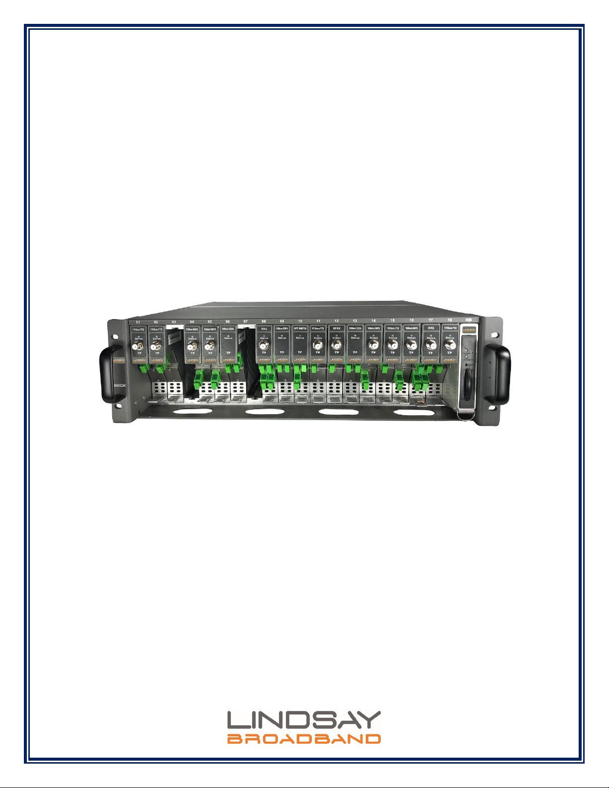
Lindsay Broadband LB-1000 3RU Optical Headend Access Platform is a converged headend, hub
access platform to enable cable operators and services providers to build, migrate or upgrade their
existing analog and/or digital networks to meet ever growing demand for advanced Video, HSD and
VOIP services.
The LB-1000 optical transmission chassis is a standard 19-inch width chassis, 3RU platform which
can accommodate 18 application modules. The standard chassis supports both 1 GHz and 1.2 GHz
modules. The back-plane interface provides inter-module communication and power distribution.
The user-friendly management interface module with a built-in TFT color touch screen displays the
status of each module. The management module supports WEB GUI management and advanced
SNMP oriented network management via standard Ethernet network interface.
The LB-1000 Optical Headend Access Platform simplifies cable operator’s transition to fiber deep
HFC and next generation FTTx architecture by offering a complete range of hot swappable, robust
optical application modules for HFC, RFoG, PON and video overlay related applications.
1.2 Features
•3RU high, 19-inch width standard chassis
•Can support up to 18 application modules per chassis (both 1 GHz & 1.2 GHz)
•Network management control module mounted in the rightmost slot
•Redundant AC-DC power modules (or DC-DC power modules)
•Hot-swappable design. Blind-mating features allows each application module to be
added/removed without any tools making it convenient and fast.
•Control Module with a 3.5” TFT provides monitoring and setup. Touch screen folds into
control module to save space.
2-2035 Fisher Dr, Peterborough, ON K9J 6X6 Canada | Tel: +1.705.742.1350 or +1.800.465.7046 | Email: [email protected]
2 |Page
LB-1000 CHASSIS
User Manual
1.3 Specifications
Parameter
Specification
Power, Environmental & Physical
Operating Input Voltage
100-240 VAC @ 50-60 Hz or -48 VDC
Power Consumption of Fully
Loaded Rack
≤ 360 W (1)
Power Consumption of Empty
Rack
(only control module plugged in)
≤ 20 W (1)
Relative Humidity
Max. 95% Non-condensing
Mounting
3RU, 19’’ standard rack mount
Inside Space Available for
Modules
18 slots for modules + 1 system management control module +
2 power supplies (power supplies on top, rear of chassis)
Operating Temperature
-20°C to +50°C (-4°F to +122°F)
Storage Temperature
-40°C to +85°C (-40°F to +185°F)
Dimensions (H x W x D)
5.2"H x 19.0"W x 19.7"D (13.3H x 48.3W x 50.0D cm)
Weight
12.2 lb (6 kg)
NOTE:
(1) Including LB-1000-PS + LB-1000-CM (from line voltage)

2-2035 Fisher Dr, Peterborough, ON K9J 6X6 Canada | Tel: +1.705.742.1350 or +1.800.465.7046 | Email: [email protected]
3 |Page
LB-1000 CHASSIS
User Manual
2.0 SAFETY NOTES
Failure to comply with these safety precautions and with the general or specific safety precautions
described elsewhere in the LB-1000 series manual violates the safety standards of the design,
manufacture, and intended use of the device. Lindsay Broadband Inc. assumes no liability for the
customer’s failure to comply with these precautions.
CAUTION: Ensure that the correct input voltage is available on AC or DC power entry port of the
"LB-1000 Power Supply module".
CAUTION: Do not operate the chassis outside of its maximum ratings. Doing so may result in
unsatisfactory performance, unit failure, shortened unit life span, or a safety hazard.
CAUTION: Do not attempt to modify or service any part of this chassis not specifically referred to
as replaceable in this manual. Doing so voids the warranty. Return the chassis to company for
service and repair.
CAUTION: No chassis should be operated in an ambient environment above 50ºC (122ºF).
CAUTION: Store the chassis away from corrosive materials, at a temperature between -40 and
+85ºC (-40 to +185ºF), and with no more than 95% humidity, non-condensing.
CAUTION: Two people are required to install the chassis. The chassis should be installed without
modules.
CAUTION: To avoid damaging the touchscreen LCD, please do not tap it with anything sharp or
apply excessive pressure to it with your fingertips. It is recommended to use fingers when you use
the touch screen LCD.
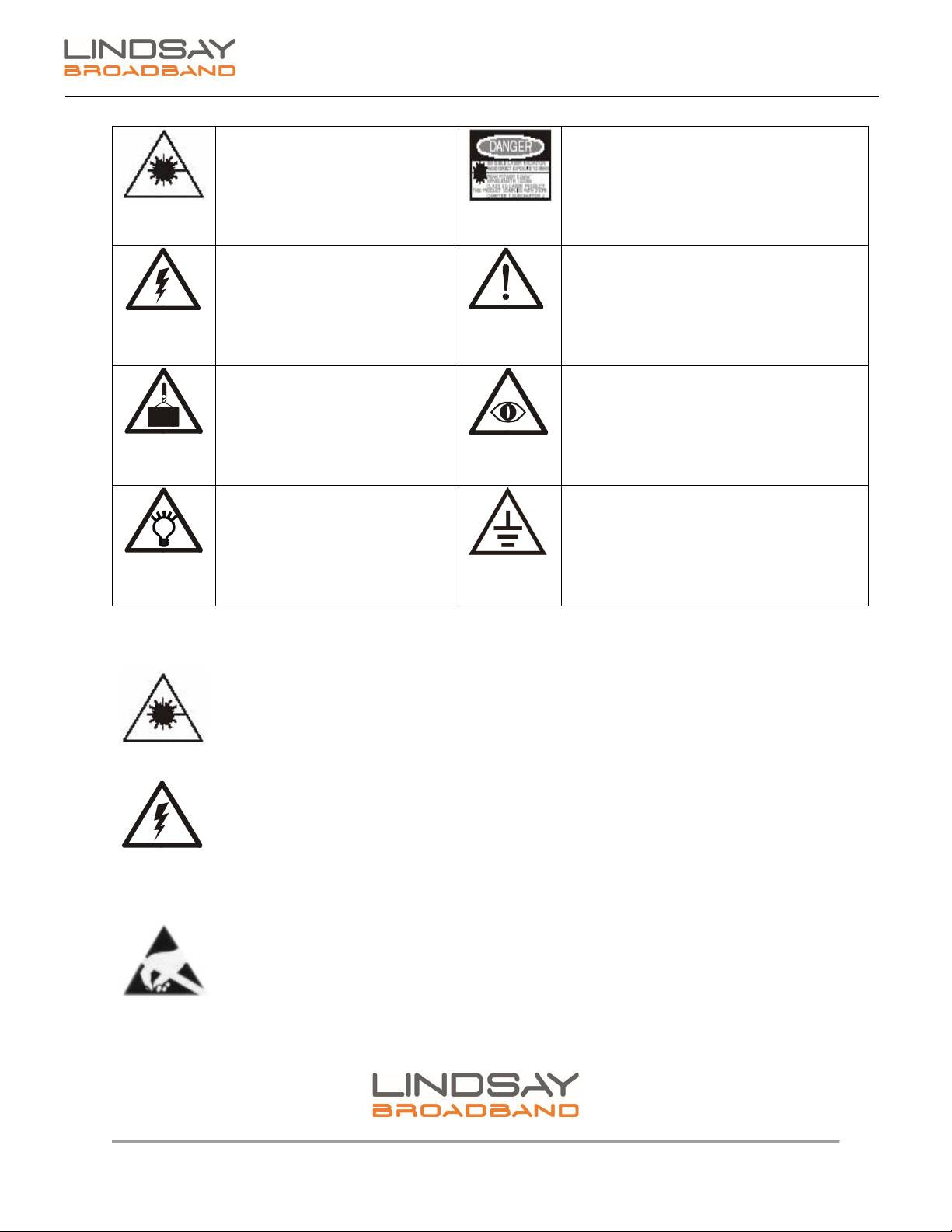
Special symbols that possibly appear on the equipment
NO SERVICEABLE PARTS INSIDE. REFER SERVICING TO QUALIFIED SERVICE PERSONNEL.
2-2035 Fisher Dr, Peterborough, ON K9J 6X6 Canada | Tel: +1.705.742.1350 or +1.800.465.7046 | Email: [email protected]
4 |Page
LB-1000 CHASSIS
User Manual
Warning of laser light
Warning of laser light
Warning of electrical
shock
Important Warning
Warning of drop
Warning of signal interruption
Prompt of
important information
Grounding device of the
equipment
Notes:
Do not directly look at the optical connector of a live transmitter due to invisible
laser light, eye damage could occur.
Do not remove the equipment cover (or back cover). Do not attempt to modify or
service any part of this chassis not specifically referred to as replaceable in this
manual. All the repairs must be performed by qualified repair men. To prevent fire
or electrical shock accidents, do not leave the equipment in rain or place it in damp
environments. Never place any object which contains liquid on the equipment.
Do not remove the equipment cover. Do not touch the electronic or optoelectronic
components in the equipment to avoid Electrostatic discharge (ESD) damage.

2-2035 Fisher Dr, Peterborough, ON K9J 6X6 Canada | Tel: +1.705.742.1350 or +1.800.465.7046 | Email: [email protected]
5 |Page
LB-1000 CHASSIS
User Manual
Note: To prevent fire accidents, a fuse may be replaced only with equivalent
voltage and current ratings
. The equipment works only in the rated voltage and
frequency range. To comply with the electrical and safety codes, only use the
recommended power cables.
It is recommended to mount an AC surge arrester on the AC socket connected with
the equipment t
o protect the equipment from lightning strikes or other surge
damages.
The equipment’s grounding device must be reliably connected.

2-2035 Fisher Dr, Peterborough, ON K9J 6X6 Canada | Tel: +1.705.742.1350 or +1.800.465.7046 | Email: [email protected]
6 |Page
LB-1000 CHASSIS
User Manual
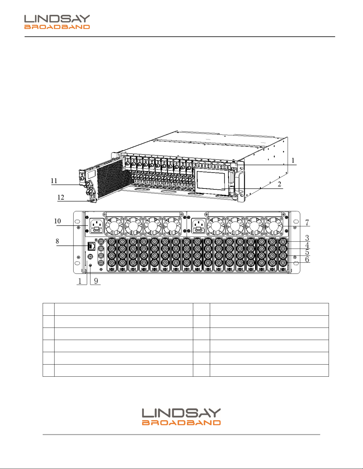
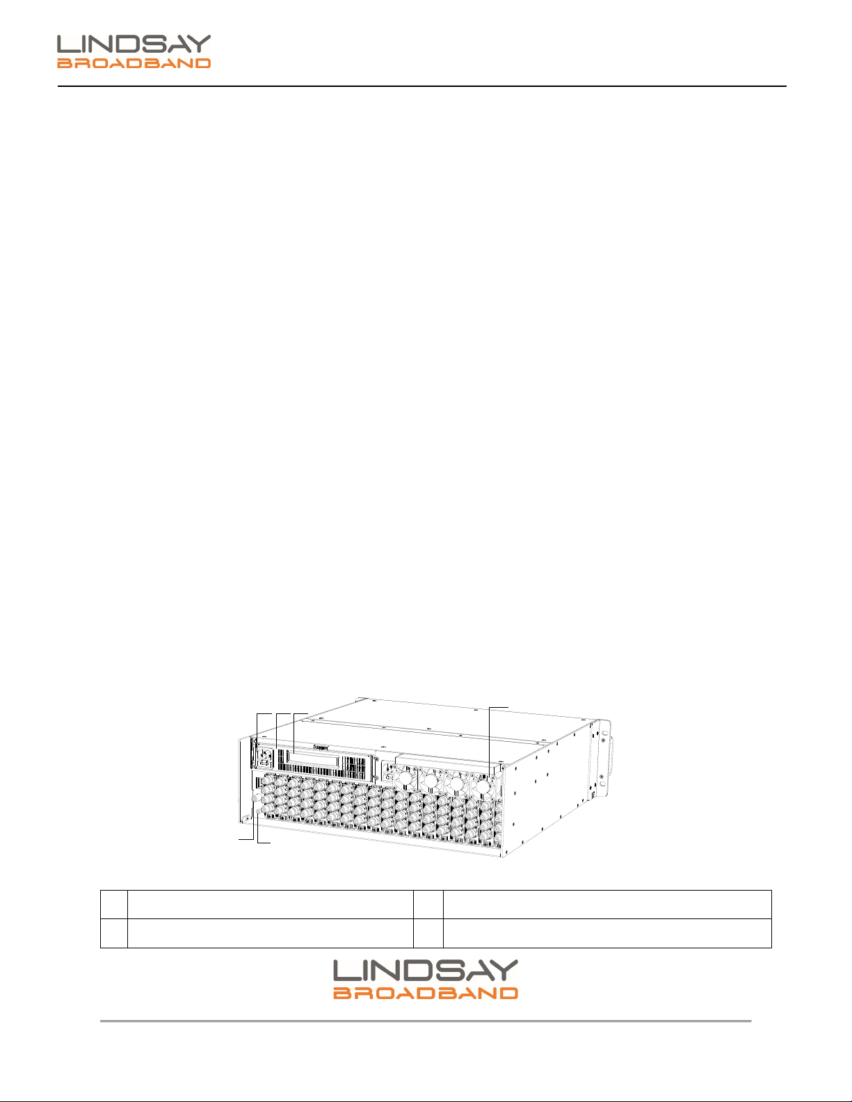
3.0 CHASSIS DESCRIPTION
Figure 1: Front and rear view of empty chassis LB-1000
1
SLOT to guide application modules installation.
2
LB-1000 Power Supply module
3
Cooling Fan module for heat dissipation
4
Floating blind mating F-type quick connector receptacles
5
GROUNDING SCREW is used for grounding chassis.
6
Chassis HANDLE
7
MOUNTING HOLES used to fix the chassis to standard 19” cabinet.

2-2035 Fisher Dr, Peterborough, ON K9J 6X6 Canada | Tel: +1.705.742.1350 or +1.800.465.7046 | Email: [email protected]
7 |Page
LB-1000 CHASSIS
User Manual
4.0 UNPACKING AND CHECKING
All units are tested and inspected before shipment and found to be free of mechanical and electrical
defects. However, upon receiving your products:
1. Examine all shipping containers for any damage due to transit.
2. Unpack all modules and chassis.
3. Keep all packing materials until your inspection is complete. When possible save the
shipping container for future reshipment and/or storage.
If damage is discovered, file a claim with the carrier immediately and notify your Lindsay Broadband
Inc. representative as soon as possible. Products deemed defective by the original purchaser must
be returned to Lindsay Broadband Inc. prepaid in the original packing material (or equivalent) with
a Return Material Authorization (RMA) from the Lindsay Broadband Inc. Equipment Service Center.

2-2035 Fisher Dr, Peterborough, ON K9J 6X6 Canada | Tel: +1.705.742.1350 or +1.800.465.7046 | Email: [email protected]
8 |Page
LB-1000 CHASSIS
User Manual
5.0 CHASSIS INSTALLATION AND INITIAL SETUP
5.1 Installation
The chassis is designed to be installed into a standard EIA 19-inch-wide rack.
1) Mount the chassis into the rack in an indoor environment following these guidelines:
•Do not block the front or back panel of any chassis.
•Maintain sufficient space in front of and behind the rack for air circulation.
2) Align the mounting holes in each of the front flanges of the chassis with holes in the rack.
Figure 2: Installation in 19 inch rack
3) Install and tighten all four mounting flange screws securely.
4) The LB-1000 comes with the requested AC or DC Power Supply module(s) pre-installed in
the LB-1000-CH chassis. Please verify that the voltage on the power entry port of the Power
Supply module corresponds to the input voltage requirement to the chassis.
5) On connecting the correct input voltage to the input of the power supply of LB-1000-CH, the
chassis should turn ON and the 8 cooling fans located on the rear panel of the chassis should
run, indicating proper operation of the chassis.
6) Install all the appropriate modules into the chassis. Begin with installing the Control Module
first (on the right most slot of the chassis labelled “NM”).
2-2035 Fisher Dr, Peterborough, ON K9J 6X6 Canada | Tel: +1.705.742.1350 or +1.800.465.7046 | Email: [email protected]
9 |Page
LB-1000 CHASSIS
User Manual
7) The unique design of the LB-1000 headend platform enables users to install any application
module in any of the general slots in the chassis. There is no specific installation sequence
for the modules. They can be installed in any of the general slots as long as they are smoothly
pushed to the specified positions and fixed.
Tip: It may be beneficial to install, connect, and configure one module at a time. Also, installing
similar type modules (i.e., Forward Transmitters or Return Receivers) in groups can make the
process easier and fiber/coax management easier.
Figure 3: Front and rear view of LB-1000 with modules
1
Network Management Control Module
7
Cooling fans for heat dissipation
2 Touch Screen that draws in/out to save space 8 RJ-45 port on Control Module
3 RF A: Channel-A RF port 9 Safety Grounding Screw
4 RF B: Channel-B RF port 10 Power Supply module
5
RF C: Channel-C RF port
11
Handle for drawing module in/out
6 RF D: Channel-D RF port 12 Latch for securing the module
8) Gently insert each module into a slot from the front of the chassis. Be careful to align the
metal guide rails on the top and bottom of the module with the guides in the interior of the
2-2035 Fisher Dr, Peterborough, ON K9J 6X6 Canada | Tel: +1.705.742.1350 or +1.800.465.7046 | Email: [email protected]
10 |Page
LB-1000 CHASSIS
User Manual
chassis housing. Using the handle completely push the application module into the slot. Once
the module is completely inserted into the slot, the latch on the bottom of the module will lock
into place with the LB-1000 chassis securing the module in the rack.
9) Ensure that the application module is reliably connected to the LB-1000-CH rear panel and
F-connectors. On successful connection, the module will automatically power on and the
status LED will turn ON.
10) If the module hasn’t been properly connected to the LB-1000-CH, it will not power up and
status LED will be OFF. In such a case, remove the application module from LB-1000-CH
slot and reinsert carefully as described in steps 8 and 9 above. See below step for safely
removing the module.
11) To remove the application module from the slot, press down on the latch located in the
bottom front of the module. The application module will unlock from the LB-1000-CH rack
and module will gently slide out. Safely draw out the module using the handle from the slot.
12) Repeat the above steps 8 to 11 to install the remaining modules in the chassis.
5.2 Power Supply Module
LB-1000 comes with an option of either using 105-264VAC or -48VDC power supply. The LB-1000
is shipped with the requested AC or DC PSU module(s) pre-installed in the chassis. The PSU’s are
installed in the two slots on the rear panel of the rack. They are inserted from the rear of the rack.
Their rear parts are locked by the cooling fan modules. When a power module is to be removed,
remove the cooling fan module first.
2 1 3 4
56
Figure 4: Rear view of the LB-1000 showing PSU
1
Power module
4
Cooling fan module
2
Power socket of power module
5
Network Management Control Module
2-2035 Fisher Dr, Peterborough, ON K9J 6X6 Canada | Tel: +1.705.742.1350 or +1.800.465.7046 | Email: [email protected]
11 |Page
LB-1000 CHASSIS
User Manual
3
Handle of power module
6
Safety grounding screw
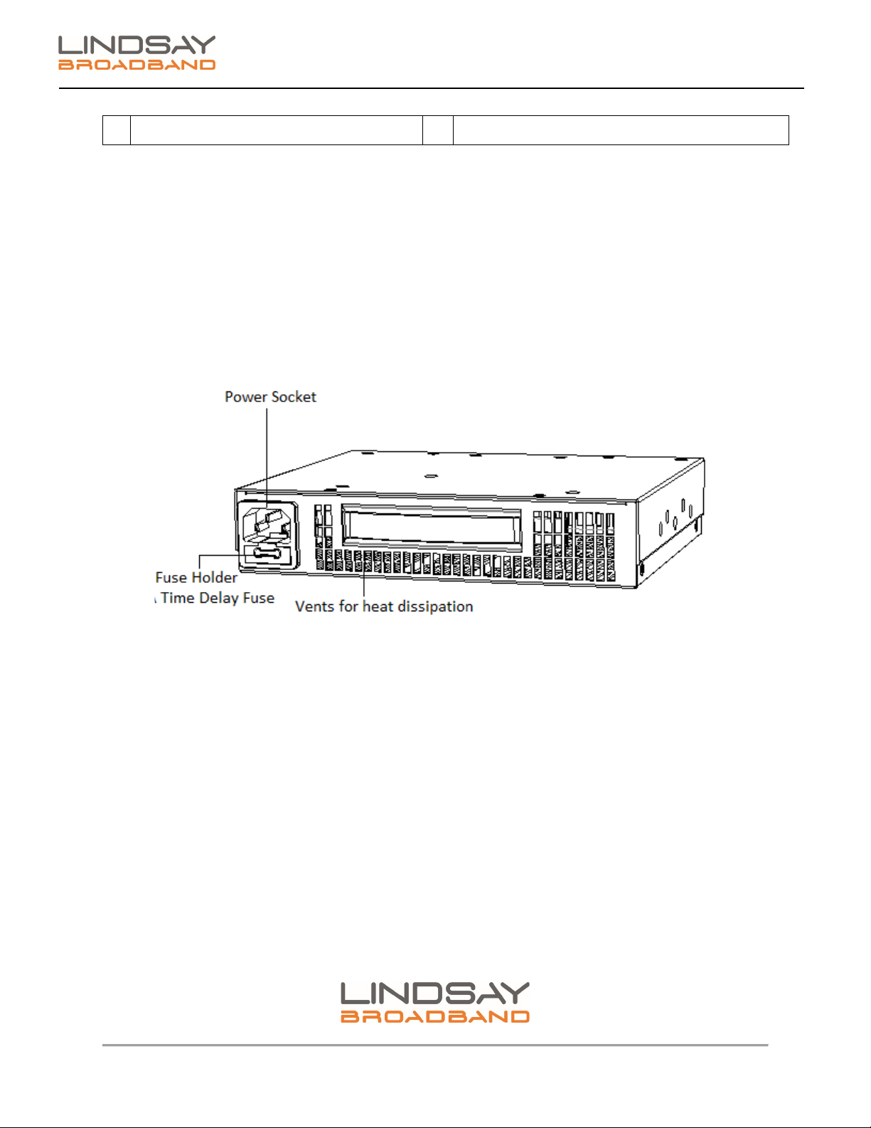
The rear panel of the power module has heat vents and connection for power and communication
transfer throughout the chassis. The front panel has heat dissipation vents, power fuse holder and
power supply handle.
The Power module has protective functions such as overload protection, over-voltage protection,
short-circuit protection, overheating protection, and start-up delay. A single power supply can
provide the required power for a fully-configured chassis. Dual-power supplies operate in load
sharing and redundant mode. The power supply status can be displayed on the control module or
monitored by standard SNMP network management software.
Figure 5: LB-1000 PSU

2-2035 Fisher Dr, Peterborough, ON K9J 6X6 Canada | Tel: +1.705.742.1350 or +1.800.465.7046 | Email: [email protected]
12 |Page
LB-1000 CHASSIS
User Manual
6.0 WARRANTY AND RMA POLICY
2-2035 Fisher Dr, Peterborough, ON K9J 6X6 Canada | Tel: +1.705.742.1350 or +1.800.465.7046 | Email: [email protected]
13 |Page
LB-1000 CHASSIS
User Manual
Lindsay Broadband Return Material Authorization Policy
Send your returns to:
Lindsay Broadband Inc.
2-2035 Fisher Dr.
Peterborough, ON Canada K9J 6X6
Attn: Product Returns
All shipments are to be pre-paid by the sender. No COD’s will be accepted.
A Return Material Authorization (RMA) Number is Required On all Product Returns (Regardless if
Product is Being Returned to Repair or credit)
Product Received at the Lindsay Broadband Factory
Without an RMA Number will be Returned to Sender
RMA number must be used when returning product for credit or repair. Use of RMA numbers will ensure
efficient processing. When returning product to Lindsay Broadband, please follow the simple steps below (in
the order that they appear):
RETURNS
1. Fill out the Product Return Authorization Form indicating product information. Repair items do not require original invoice
information, but it is helpful to determine warranty eligibility.
2. Contact Lindsay Broadband Inc. Service Department in one of three ways:
•E-mail to: [email protected] (recommended method) Include all of the information from the product
Authorization Form, or,
•Fax the Product Authorization Form to 1-705-742-7669 or,
•Call Lindsay Broadband Inc. @ 800-465-7046 Ext 235 / 261
3. After completing Steps 1 & 2, an RMA number will be assigned to you.
4. Securely pack the product and mark the box with your RMA #. If shipping multiple boxes, all boxes should be marked with the
RMA #. The RMA # must be placed near your return address in large, bold print (approximately 2” in height). Please see the
address label below as an example of the relative size location of the RMA #.
Sample Address label with RMA #
John Smith
ABC Company RMA 1234
123 Smith Street
Anytown, USA 00000
Lindsay Broadband Inc
2-2035 Fisher Dr.,
Peterborough, ON K9J 6X6

2-2035 Fisher Dr, Peterborough, ON K9J 6X6 Canada | Tel: +1.705.742.1350 or +1.800.465.7046 | Email: [email protected]
14 |Page
LB-1000 CHASSIS
User Manual
Lindsay Broadband Return Material Authorization (RMA) Form
Company
Contact Name:
Address:
City:
Prov/State:
Postal Code/Zip:
Phone: #:
Fax #:
Email address (if applicable)
RMA #
(To be supplied by Lindsay Broadband)
Date:
___________
Reason for return
Qty.
LBI Part #
Description
P.O. #
P.O.
Date
Service Repair Policy
Lindsay Broadband product may be
returned for repair under the following
condition:
1. Please contact Lindsay
Broadband Service Dept. to
obtain an RMA#.
2. Please supply requested
information to verify 2warranty
coverage.
Any shipments received by Lindsay
Broadband without an RMA # will be
refused.
Credit Return Policy
Lindsay Broadband products may be
retuned for credit under the following
conditions:
1. Products are unused and
undamaged.
2. Products are accompanied by a
one dollar (new purchase) for
one dollar (credit return) order.
3. Products were purchased within
one year from credit return date
and are in a current catalog.
4. Products are subject to a 10%
per RMA and $2.00 per line item.
5. Products that are custom made
are subject to an additional
charge for conversion of not less
than 20% and not more than
50% of the FFP price.
6. Product that require factory
repacking are subject to an
additional charge for material
and labour.
7. Please contact Lindsay
Broadband Customer Service to
obtain an RMA#.
Any shipments received by
Lindsay Broadband without
an RMA# will be refused.
Note: Products that are judged by
Lindsay Broadband Inc. upon
receipt as being unacceptable for
credit shall be returned to sender
at their expense.
SHIPPING INSTRUCTIONS
1. Make Sure to Obtain an RMA#
and mark a box(s) accordingly
2. Ship Only Items Authorized
3. Enclose Packing Slip & Product
Return Authorization Form
4. Ship Prepaid Only to :
Lindsay Broadband Inc
2035-2 Fisher Dr.
Peterborough, ON CANADA
K9J 6X6
Attn: Product Returns
Table of contents
Popular Chassis manuals by other brands


Overland Storage
Overland Storage SnapSAN S1000 Replacement instructions

Philips
Philips LC4.1E A Service manual

Supermicro
Supermicro SCF418 Series user manual

Supermicro
Supermicro SC823MTQ-R700LPB user manual

HP
HP A7503-S Product End-of-Life Disassembly Instructions

SilverStone
SilverStone RMS08 Series manual


