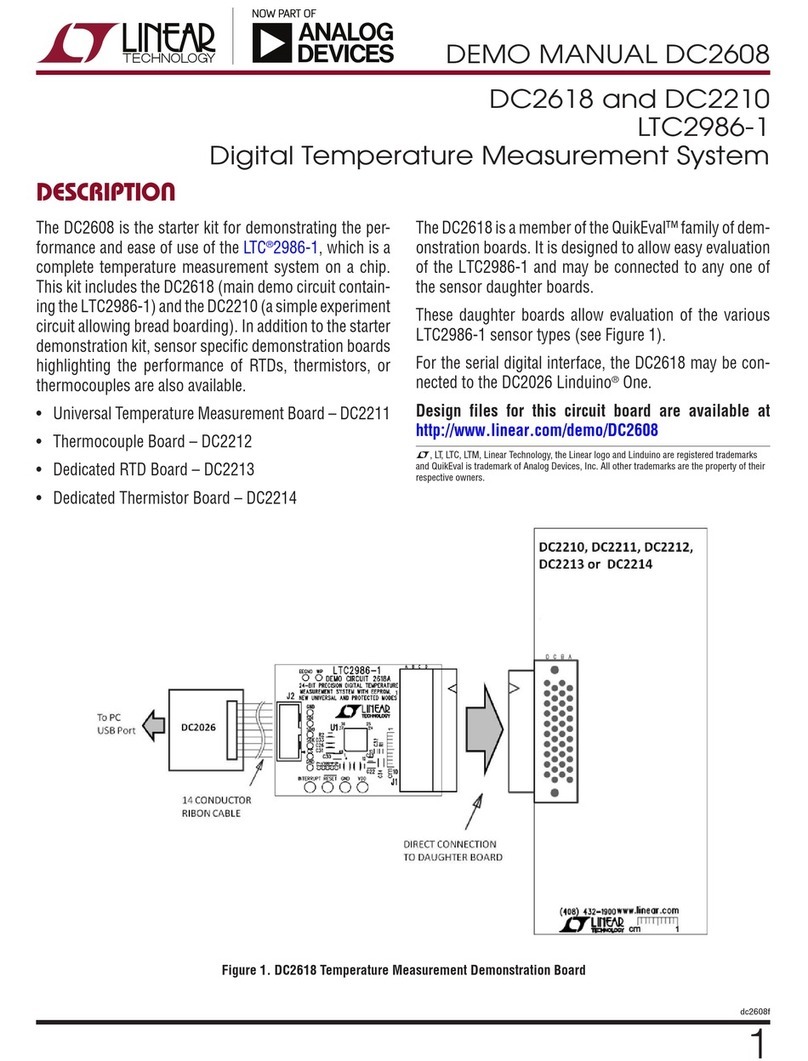
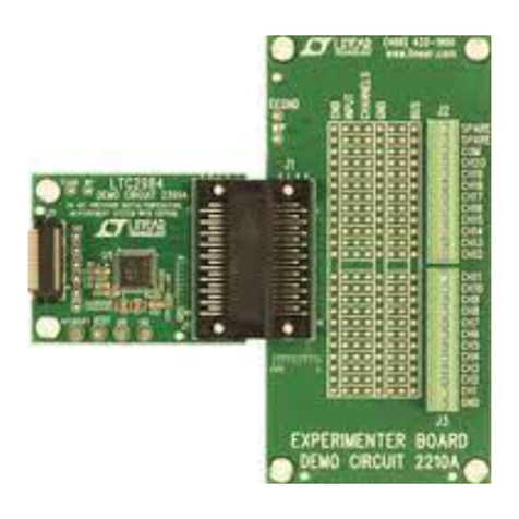
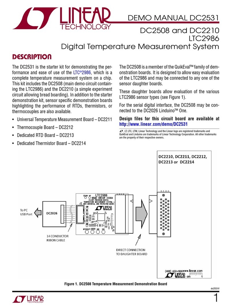
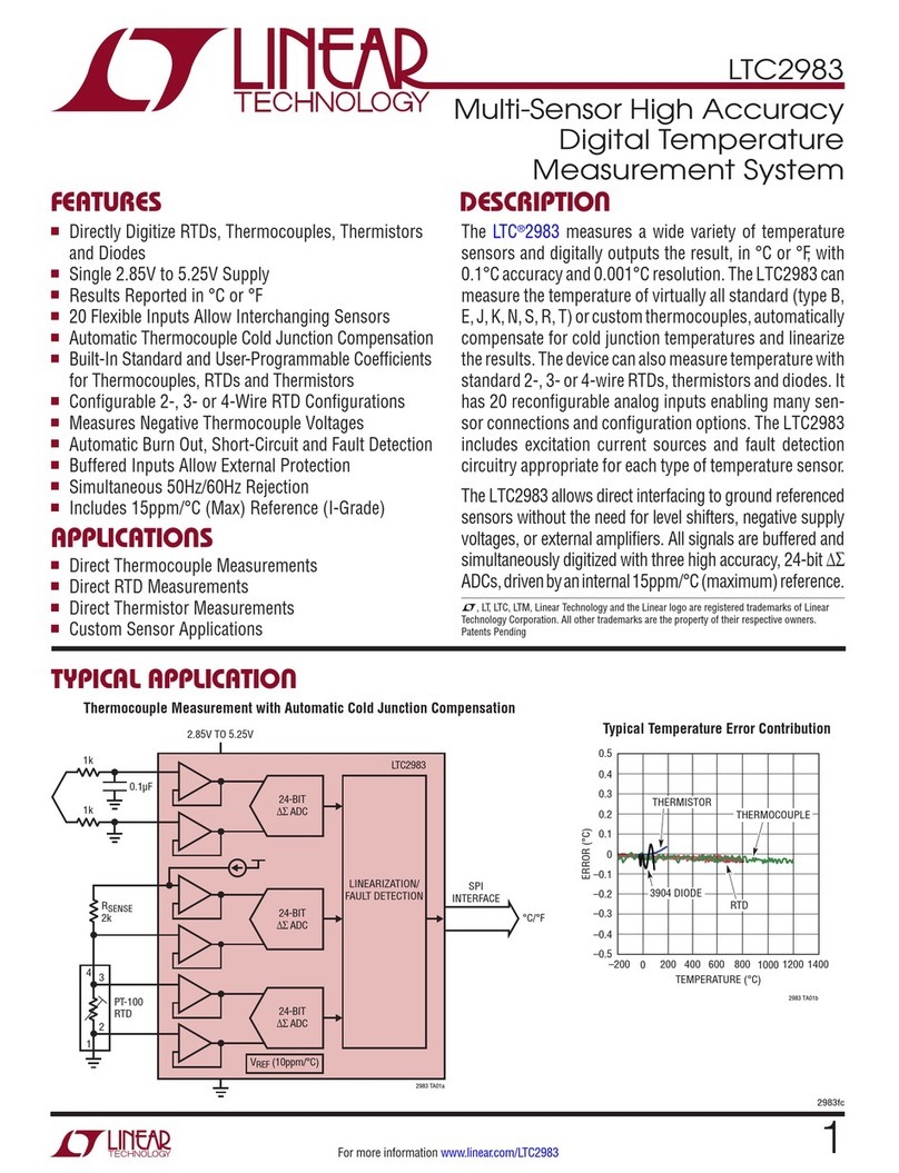
Linear Technology LTC3305EFE Quick setup guide

1
dc2043af
DEMO MANUAL DC2043A
Description
LTC3305EFE
Lead Acid Battery Balancer
Demonstration circuit2043Ais alead AcidBatteryBalancer
featuring the LT C
®
3305. The LTC3305 balances up to 4
lead acid batteries connected in series and incorporates all
voltage monitoring, gate drive and fault detection circuitry.
The LTC3305 employs an auxiliary battery or an alternative
storage cell to transfer charge to or from each individual
battery within the stack. There are two operating modes,
TIMER mode and CONTINUOUS mode, selected by the
MODE pin. In TIMER mode, once the balancing operation
is complete, the LTC3305 goes to a low power state for
a programmed time and then periodically rebalances the
L, LT, LTC, LTM, Linear Technology and the Linear logo are registered trademarks of Linear
Technology Corporation. All other trademarks are the property of their respective owners.
BoarD photo
batteries. In CONTINUOUS mode, the balancing operation
continues even after the batteries are balanced to their
programmed termination voltage.
The LTC3305EFE is available in a 7mm ×7mm 38-lead
TSSOP surface mount package with exposed pad.
Design files for this circuit board are available at
http://www.linear.com/demo/DC2043A
Figure 1. DC2043A Demo Board Figure 2. Thermal Image of DC2043A

2
dc2043af
DEMO MANUAL DC2043A
operatinG principLe
Refer to the block diagram within the LTC3305 data sheet
for its operating principle.
The LTC3305 balances batteries using an auxiliary cell
or an alternate storage cell as a charge reservoir. The
LTC3305 controls external N Channel MOSFET switches
in a preprogrammed sequence to connect a battery in the
stack to an auxiliary cell. Charge is transferred to or from
the auxiliary cell when it is connected to a battery.
The LTC3305 can operate in one of two modes, TIMER
mode or CONTINUOUS mode, programmable via the
MODE pin. Balancing operation begins once the CBOOST
capacitor is charged to at least 6.95V. The EN1 and EN2
pins select the number of batteries in the stack.
EN1 EN2 Application
0 0 SHUTDOWN
0 1 2 Battery Stack
1 0 3 Battery Stack
1 1 4 Battery Stack
With the MODE pin set to 0 the LTC3305 will operate in the
TIMER Mode. The BAL pin will be pulled low, indicating
that the part is enabled and balancing the battery stack.
The balancing operation begins with the terminal of the
auxiliary cell connected to the negative terminal of BAT1,
the lowest battery in the stack. The bottom switches that
connect the negative terminals of BAT1 to the Auxiliary
cell’s negative terminal are turned on. After a 50ms delay,
the voltages across the auxiliary cell and BAT1 are com-
pared by the termination sense comparator. If the voltage
difference between the auxiliary cell and BAT1 is less than
the selected termination voltage, the battery is deemed to
be in a balance state with respect to the auxiliary cell. The
bottom switches will be turned off and the next battery
within the stack will be connected.
If the voltage difference between the auxiliary cell and
BAT1 is greater than the selected termination voltage, the
top switches that connect the positive terminal of BAT1
to the auxiliary cell’s positive terminals through the PTC
thermistor are turned on. Current is limited by the PTC
thermistor. Figure 3 shows the startup battery current
where the PTC is limiting as it heats up. Figure 4 is the
steady state battery current after the PTC has reached its
thermal equilibrium. After a 50ms delay, the termination
sense comparator starts to monitor the voltage across
the auxiliary cell and the battery. The battery will remain
connected to the auxiliary cell until the voltage difference
decreases to the selected termination voltage or a tBAT
timeout occurs.
At this point all switches are turned off and the second
battery in the stack will be connected to the auxiliary cell
after a 50ms delay. This 50ms delay provides a break be-
fore make function before the next battery is connect-ed.
The cycle will be repeated for each battery in the stack.
performance summary
Specifications are at TA= 25°C
SYMBOL PARAMETER CONDITIONS MIN MAX UNITS
VBAT Battery Voltage Range 4.0 to 16.0 V
VTERMINATE Termination Voltage Range TERM2 = 0, TERM1 = 0 ±5 to ±20 mV
VTERMINATE Termination Voltage Range TERM2 = 0, TERM1 = 1 ±17.5 to ±32.5 mV
VTERMINATE Termination Voltage Range TERM2 = 1, TERM1 = 0 ±42.5 to ±57.5 mV
VTERMINATE Termination Voltage Range TERM2 = 1, TERM1 = 1 ±90 to ±110 mV
VREG Regulator Output Voltage Range IVREG = 200µA 2.4 to 2.6 V

3
dc2043af
DEMO MANUAL DC2043A
operatinG principLe
100mA/DIV
BAT CURRENT
BATTERY BALANCING CURRENT
0.25V DIFFERENTIAL BETWEEN
BATTERY AND AUX BATTERY
dc2043a F03
100mA/DIV
BAT CURRENT
BATTERY BALANCING CURRENT
0.25V DIFFERENTIAL BETWEEN
BATTERY AND AUX BATTERY
dc2043a F04
Figure 3. Start-Up Battery Balancing Current
Figure 4. Steady State Battery Balancing Current
Once all batteries in the stack are balanced the DONE pin is
pulled low, the BAL pin is in its high state and the LTC3305
is put into a low power off state. The stack is deemed
balanced when for a four battery stack, the termination
sense comparator detects VTERMINATE on five consecutive
cycles that connects each of the batteries to the auxiliary
cell using the bottom switches only.
In TIMER mode, the balancing operation continues for a
maximum of the programmed tON time. After the tON time,
LTC3305 is put into alow power off state for a programmed
tOFF time, even though the batteries may not be balanced.
Once the tOFF time expires, the LTC3305 is put into the
ON state and normal operation resumes. The BAL pin is
in its high impedance state if the part is in the OFF state
or when the part is in shutdown.
With the MODE pin set to 1, the LTC3305 will operate in the
CONTINUOUS Mode. The part functions in much the same
way as in the TIMER mode with the following differences.
1. There are no ON or OFF states. The balancing operation
continues even if the stack is in balance. The balanc-
ing operation is terminated only if the part is put into
shutdown. The BAL pin is always pulled low.
2. In CONTINUOUS mode, the top switches are turned
on and balancing operation on a battery is terminated
by the tBAT time out. Since the auxiliary cell remains
connected to the battery until a tBAT time out, its volt-
age can change before it connects to the next battery
in the stack. As a result, when the stack is balanced
and the DONE pin is pulled low, the voltages across
individual batteries in the stack may differ by more than
the programmed VTERMINATE. In the worst case, when
the capacity of the auxiliary cell is much smaller than
the battery, the individual battery voltages will differ by
twice the programmed VTERMINATE when balanced.
The LTC3305 provides undervoltage and overvoltage
threshold detection that can be programmed using
resistors that are connected between the ISET, VL and
VH pins and ground. The voltages set on VL and VH are
scaled by a factor of 10, setting the battery undervoltage
and overvoltage thresholds, respectively.
When an undervoltage or overvoltage fault condition is
detected, the corresponding UVFLT or OVFLT pin is pulled
low. The balancing operation is not interrupted during this
time. If the fault condition goes away during balancing, the
corresponding faultpin isput intoitshigh impedancestate.

4
dc2043af
DEMO MANUAL DC2043A
QuicK start proceDure
Using short twisted pair leads for any power connections,
with all loads and power supplies off, refer to Figure 5 for
the proper measurement and equipment setup.
Follow the procedure below:
1. Before connecting PS1-PS5 to the DC2043A, the
power supplies must have its current limit set to 5A.
For most power supplies with a current limit adjust-
ment feature the procedure to set the current limit is
as follows. Turn the voltage and current adjustment
to minimum. Short the outputs terminals and turn the
voltage adjustment to maximum. Adjust the current
limit to 5A for PS1. Turn the voltage adjustment to
minimum and remove the short between the output
terminals. Repeat for PS2-PS5 The power supplies
are now current limited to 5A .
a. Initial Jumper and PS settings:
JP1(MODE) = CONT JP2 (EN) = SD
JP3(TERM1) = 1 JP4 (TERM2) = 1
PS1 = Off PS2 = Off PS3 = OFF
PS4 = OFF PS5 = Off PS6 = Off
2. Connect power supplies, load resistors and meters as
shown in Figure 5. Turn on PS1 and slowly increase
voltage to 2.0V while monitoring the input current. If
the current remains less than 200mA, increase PS1
to 12.0V. Repeat for PS2-PS4.
3. Turn on PS5 and slowly increase voltage to 2.0V while
monitoringthe inputcurrent. Ifthe currentremains less
than 200mA, increase PS5 to 11.8V. Turn on PS6 and
slowly increase voltage to 2.0V while monitoring the
input current. If the current remains less than 20mA,
increase PS6 to 5.0V.
4. Measure the voltage from the VREG Turret to ground.
The voltage should read approximately 2.6V. Measure
the voltage from the BOOST Test Point to V4. The volt-
age should read approximately 0V. No LED should be
on.
5. Set JP2 to EN. Measure the voltage from the BOOST
TestPoint toV4. Thevoltage shouldread approximately
8.5V.
6. Measurethe voltagefromthe ISET Test Pointto ground.
The voltage should read approximately 1.2V.
7. Measure the voltage from the VH Test Point to ground.
The voltage should read approximately 1.52V.
8. Measure the voltage from the VL Test Point to ground.
The voltage should read approximately 0.95V.
9. With JP1 set to CONT, JP2 set to EN, JP3 set to 1 and
JP4 set to 1, observe that the BATX and BATY LEDs
are cycling through their four states.
BATX
LED
BATY
LED
Active
Battery
OFF OFF BAT1
OFF ON BAT2
ON ON BAT3
ON OFF BAT4
10. Decrease PS1 and PS5 to 9.4V and observe that while
the BATX and BATY are off, the UVFLT LED is on.
11. Increase PS1 and PS5 to 15.9V and observe that
while the BATX and BATY are off, the OVFLT LED is
on. Decrease PS1and PS2 to 12.0V.
12. Decrease PS2 to 11.5V. Set JP1 to TIMER. Observe
that the BATX LED is off and BATY LED is on the ma-
jority of the time .Increase PS2 to 12V and observe
that the balancing action stops. The BAL LED will be
off and the DONE LED will be on.
13. Set JP1 to CONT and JP2 to SD. Set PS5 to 11.8V.
Observe that balancing action has stopped and no
LEDs are on. Set JP2 to EN and observe that balancing
action starts.
14. Turn off all power supplies

5
dc2043af
DEMO MANUAL DC2043A
QuicK start proceDure
10Ω
25W
5V
PS5
+
PS4
+
PS3
+
PS2
+
PS1
+
10Ω
25W
10Ω
25W
10Ω
25W
5Ω
50W
PS6
+
Figure 5. Proper Measurement Equipment Set-Up

6
dc2043af
DEMO MANUAL DC2043A
parts List
ITEM QTY REFERENCE PART DESCRIPTION MANUFACTURER/PART NUMBER
Required Circuit Components
1 4 C1-C4 CAP.,X7R, 4.7µF, 25V, 20%, 0805 TDK, C2012X7R1E475M
2 7 C5, C6, C12-C16 CAP.,X7R, 10µF, 25V, 20%, 1206 MURATA, GRM31CR71E106KA12
3 1 C7 CAP.,C0G, 0.033µF, 50V, 5%, 0805 TDK, CGA4J2C0G1H333J125AA
4 2 C8, C9 CAP.,C0G, 0.01µF, 50V, 5%, 0805 TDK, CGA4C2C0G1H103J060AA
5 1 C10 CAP., X7R, 1.0µF, 16V, 10%, 0603 MURATA, GRM188R71C105KA12D
6 2 D1-D2 SMD, SCHOTTKY DIODE, 1A, 100V, SOD123 CENTRAL SEMI, CMMSH1-100G
7 10 Q1-Q3_1, Q3_2, Q4-Q9 MOSFET, 100V, 0.009Ω, 60A,POWERPAK-SO-8 VISHAY, SiR882DP
8 8 R1, R2, R4-R9 RES, CHIP, 6.04k, 1/16W, 1%, 0402 VISHAY, CRCW04026K04FKED
9 1 R3 RES, CHIP, 3.01k, 1/16W, 1%, 0402 VISHAY, CRCW04023K01FKED
10 2 R10, R11 RES, CHIP,12.1k, 1/8W, 1%, 0805 VISHAY, CRCW080512K1FKED
11 7 R12-R18 RES, CHIP, 10.0, 1/16W, 1%, 0402 VISHAY, CRCW040210R0FKED
12 2 R19, R34 RES, CHIP, 665, 1/2W, 1%, 1210 VISHAY, CRCW1210665RFKED
13 1 R20 RES, CHIP, 12.1k, 1/16W, 1%, 0402 VISHAY, CRCW040212K1FKED
14 1 R21 RES, CHIP, 46.4k, 1/16W, 1%, 0402 VISHAY, CRCW040246K4FKED
15 1 R22 RES, CHIP, 28.7k, 1/16W, 1%, 0402 VISHAY, CRCW040228K7FKED
16 4 R30-R33 RES, CHIP, 1.82M, 1/16W, 1%, 0402 VISHAY, CRCW04021M82FKED
17 1 R35 RES, CHIP, 249, 1/4W, 1%, 1206 VISHAY, CRCW1206249RFKED
18 1 RT1 DISC, TH, PTC, 0.15Ω, 16V, 10.1mm DIA, MURATA, PTGLESARR15M1B51B0
19 1 U1 IC,SMT, LEAD ACID BATTERY BALANCER/EFE LINEAR, LTC3305EFE#PBF
Additional Demo Board Circuit Components
1 1 C11 CAP., X7R, 4.7µF, 25V, 20%, 0805 TDK, C2012X7R1E475M
2 3 D3, D6, D7 SMD, RED LED, 0603 LITE ON, LTST-C193KRKT-5A
3 4 D4, D5, D8, D9 SMD, GREEN LED, 0603 LITE ON, LTST-C193KGKT-5A
4 4 F1-F4 SMD, FUSE, 7A, FAST ACTING, 1206 32VDC BUSSMANN, 3216FF7-R
5 6 F5-F10 SMD, FUSE, 1/4A, FAST ACTING, 1206 32VDC BUSSMANN, 3216FF250-R
6 1 Q10 MOSFET, P-CHANNEL, 20V, 0.085Ω, 0.95ASOT-23 CENTRAL SEMI, CMPDM8120
7 7 R23-R29 RES, CHIP, 1.00k, 1/16W, 1%, 0402 VISHAY, CRCW04021K00FKED
8 1 R36 RES, CHIP, 100k, 1/16W, 1%, 0402 VISHAY, CRCW0402100KFKED
9 7 R37-R43 RES, CHIP, 2.00k, 1/16W, 1%, 0402 VISHAY, CRCW04022K00FKED
Hardware: For Demo Board Only
1 7 E1-E7 Turret, 0.061" MILL-MAX, 2308-2-00-80-00-00-07-0
2 17 E8-E24 Turret, 0.09" MILL-MAX, 2501-2-00-80-00-00-07-0
3 4 JP1-JP4 HEADER, 3PINS, 2mm SAMTEC, TMM-103-02-L-S
4 4 JP1-JP4 SHUNT 2mm SAMTEC, 2SN-BK-G
5 6 STAND-OFF, NYLON 0.375" tall KEYSTONE, 8832 (SNAP ON)

7
dc2043af
DEMO MANUAL DC2043A
Information furnished by Linear Technology Corporation is believed to be accurate and reliable.
However, no responsibility is assumed for its use. Linear Technology Corporation makes no representa-
tion that the interconnection of its circuits as described herein will not infringe on existing patent rights.
schematic DiaGram
TERM1TERM2 EN MODE
00 SD TIMER
11EN CONT.
DONE BAL UVFLT OVFLT
BATY BATX
PTCFLT
NOTES: UNLESS OTHERWISE SPECIFIED
1. ALL RESISTORS ARE IN OHMS, 0402, 1%, 1/16W.
3. INSTALL SHUNTS ON JUMPERS AS SHOWN.
2. ALL CAPACITORS ARE IN MICROFARADS, 0805, 20%, 25V.
3.3V - 5.5V
9.5V-15.5V
9.5V-15.5V
9.5V-15.5V
9.5V-15.5V
9.5V-15.5V
2.5V
ON
OFF
OFF
OFF
ON
0
0
0
1
1
1 1
TERM1 TERM2
0
± 12.5mV
± 25mV
±50mV
TERMINATION
VOLTAGE
± 100mV
BATTERY BEING
BALANCED
BATTERY 1
BATTERY 2
BATTERY 3
BATTERY 4
ON
OFF
ON
BATX
LED
BATY
LED
BAT3_K
BAT4_K
NG5
NG4
NG3
NG2
NG6
NG7
NG1
NG9
NG8
NG1
NG2
NG3
NG4
NG5
NG6
NG7
NG8
NG9
BAT4
BAT4
VREG
BAT3
PTCFLTB
DONEB
BALB
UVFLTB
OVFLTB
BATY
BATX
PTCFLTB DONEB BALB UVFLTB OVFLTB BATY BATX
BAT2_K
GND
BALB
GND_K
GND_K
GND_K
BAT1
GND_K
AUXP_K
AUXN_K
BAT1_K
GND_K
BAT2
BAT1_K
BAT2_K
BAT3_K
BAT4_K
SIZE
DATE:
.VER.ONCI
SHEET OF
TITLE:
APPROVALS
PCB DES.
APP ENG.
TECHNOLOGY Fax: (408)434-0507
Milpitas, CA 95035
Phone: (408)432-1900
1630 McCarthy Blvd.
LTC Confidential-For Customer Use Only
CUSTOMER NOTICE
LINEAR TECHNOLOGY HAS MADE A BEST EFFORT TO DESIGN A
CIRCUIT THAT MEETS CUSTOMER-SUPPLIED SPECIFICATIONS;
HOWEVER, IT REMAINS THE CUSTOMER'S RESPONSIBILITY TO
VERIFY PROPER AND RELIABLE OPERATION IN THE ACTUAL
APPLICATION. COMPONENT SUBSTITUTION AND PRINTED
CIRCUIT BOARD LAYOUT MAY SIGNIFICANTLY AFFECT CIRCUIT
PERFORMANCE OR RELIABILITY. CONTACT LINEAR
TECHNOLOGY APPLICATIONS ENGINEERING FOR ASSISTANCE.
THIS CIRCUIT IS PROPRIETARY TO LINEAR TECHNOLOGY AND
SCHEMATIC
SUPPLIED FOR USE WITH LINEAR TECHNOLOGY PARTS.
SCALE = NONE
www.linear.com
3
DEMO CIRCUIT 2043A
1 1
LEAD ACID BATTERY BALANCER
N/A
LTC3305EFE
NC
JD
9 - 23 - 14
REVISION HISTORY
DESCRIPTION DATEAPPROVEDECO REV
JDPRODUCTION FAB 41-32-93-
REVISION HISTORY
DESCRIPTION DATEAPPROVEDECO REV
JDPRODUCTION FAB 41-32-93-
REVISION HISTORY
DESCRIPTION DATEAPPROVEDECO REV
JDPRODUCTION FAB 41-32-93-
D2 CMMSH1-100GD2 CMMSH1-100G
E20
BAT2_K
E20
BAT2_K
TP12
NG9
TP12
NG9
R25 1kR25 1k
JP1JP1
Q4
SiR882DP
Q4
SiR882DP
6
4
2
3
18
5
7
R42
2k
R42
2k
R9 6.04kR9 6.04k
E24
AUXN_K
E24
AUXN_K
E5
OVFLT
E5
OVFLT
D7
RED
LED-LN
D7
RED
LED-LN
R4 6.04KR4 6.04K
R31
1.82M
R31
1.82M
Q6
SiR882DP
Q6
SiR882DP
6
4
2
3
1
8
5
7
E22
GND_K
E22
GND_K
R34 665
1210
R34 665
1210
C8
10nF
50V
5%
C8
10nF
50V
5%
C10
1uF
16V
0603
10%
C10
1uF
16V
0603
10%
R21
46.4k
R21
46.4k
R14 10R14 10
E10
BAT4
E10
BAT4
TP8
NG5
TP8
NG5
C3
4.7uF
C3
4.7uF
TP4
CTOFF
TP4
CTOFF
TP16
ISET
TP16
ISET
R7
6.04k
R7
6.04k
JP3JP3
D3
RED
LED-LN
D3
RED
LED-LN
R2
6.04K
R2
6.04K
Q7
SiR882DP
Q7
SiR882DP
6
4
2
3
1
8
5
7
E6
BATY
E6
BATY
Q8
SiR882DP
Q8
SiR882DP
6
4
2
3
18
5
7
C5
10uF
1206
C5
10uF
1206
TP3
CTON
TP3
CTON
C1
4.7uF
C1
4.7uF
R26 1kR26 1k
JP2JP2
Q3_2
SiR882DP
Q3_2
SiR882DP
6
4
2
3
18
5
7
Q9
SiR882DP
Q9
SiR882DP
6
4
2
3
18
5
7
R43
2k
R43
2k
D4
GRN
LED-LN
D4
GRN
LED-LN
R32
1.82M
R32
1.82M
F2
7A
1206
F2
7A
1206
F7
1/4A
1206
F7
1/4A
1206
Q2
SiR882DP
Q2
SiR882DP
6
4
2
3
1
8
5
7
C7
33nF
50V
5%
C7
33nF
50V
5%
D8
GRN
LED-LN
D8
GRN
LED-LN
C14
10uF
1206
C14
10uF
1206
R39
2k
R39
2k
R5 6.04kR5 6.04k
R22
28.7k
R22
28.7k
TP18
CM
TP18
CM
TP2
CTBAT
TP2
CTBAT
TP9
NG6
TP9
NG6
E7
BATX
E7
BATX
Q1
SiR882DP
Q1
SiR882DP
6
4
2
3
1
8
5
7
E19
BAT3_K
E19
BAT3_K
R17
10
R17
10
R12 10R12 10
E14
GND
E14
GND
E2
DONE
E2
DONE
E8
AUXP
E8
AUXP
C4
4.7uF
C4
4.7uF
C6
10uF
1206
C6
10uF
1206
Q3_1
SiR882DP
Q3_1
SiR882DP
6
4
2
3
1
8
5
7
R19 665
1210
R19 665
1210
R27 1kR27 1k
F5
1/4A
1206
F5
1/4A
1206
R37
2k
R37
2k
Q10
CMPDM8120
Q10
CMPDM8120
R15
10
R15
10
TP5
NG1
TP5
NG1
R10 12.1k
0805
R10 12.1k
0805
F3
7A
1206
F3
7A
1206
U1
LTC3305EFE
U1
LTC3305EFE
MODE
35
CP
37
CM
38
BOOST
1
V4
2
V3
3
AUXP
4
AUXN
5
V2
6
V1
7
NG1
8
NG2
9
NG3
10
NG4
11
NG5
12
NG6
13
NG7
14
NG8
15
NC
36
NG9
16
BATX
17
BATY
18
OVFLT
19
UVFLT
20
BAL
21
DONE
22
PTCFLT
23
CTBAT
26
CTON
25
CTOFF
24
VL
27
VH
28
ISET
29
VREG
30
TERM2
31
TERM1
32
EN2
33
EN1
34
GND
39
D5
GRN
LED-LN
D5
GRN
LED-LN
TP17CP TP17CP
E17
VREG
E17
VREG
R40
2k
R40
2k
TP14
VL
TP14
VL
D9
GRN
LED-LN
D9
GRN
LED-LN
TP10
NG7
TP10
NG7
D1
CMMSH1-100G
D1
CMMSH1-100G
E3
BAL
E3
BAL
E13
BAT1
E13
BAT1
R23 1kR23 1k
E9
AUXN
E9
AUXN
R8 6.04KR8 6.04K
R3 3.01KR3 3.01K
F6
1/4A
1206
F6
1/4A
1206
t
RT1
PTGLESARR15M1B51B0
t
RT1
PTGLESARR15M1B51B0
12
R28 1kR28 1k
C13
10uF
1206
C13
10uF
1206
E23
AUXP_K
E23
AUXP_K
F9
1/4A
1206
F9
1/4A
1206
E21
BAT1_K
E21
BAT1_K
R33
1.82M
R33
1.82M
TP1
BOOST
TP1
BOOST
E4
UVFLT
E4
UVFLT
TP6
NG2
TP6
NG2
R6
6.04k
R6
6.04k
R1
6.04K
R1
6.04K
TP13
NG3
TP13
NG3
E12
BAT2
E12
BAT2
JP4JP4 E18
BAT4_K
E18
BAT4_K
E15
VEXT
E15
VEXT
TP11
NG8
TP11
NG8
D6
RED
LED-LN
D6
RED
LED-LN
R41
2k
R41
2k
F4
7A
1206
F4
7A
1206
R35 249
1206
R35 249
1206
R24 1kR24 1k
F10
1/4A
1206
F10
1/4A
1206
R18
10
R18
10
R36
100k
R36
100k
R13 10R13 10
R38
2k
R38
2k
R30
1.82M
R30
1.82M
TP15
VH
TP15
VH
C15
10uF
1206
C15
10uF
1206
C2
4.7uF
C2
4.7uF
C9
10nF
50V
5%
C9
10nF
50V
5%
C16
10uF
1206
C16
10uF
1206
C12
10uF
1206
C12
10uF
1206
R29 1kR29 1k
E1
PTCFLT
E1
PTCFLT
R20
12.1k
R20
12.1k
C11
4.7uF
C11
4.7uF
TP7
NG4
TP7
NG4
F1
7A
1206
F1
7A
1206
F8
1/4A
1206
F8
1/4A
1206
E11
BAT3
E11
BAT3
R16
10
R16
10
R11 12.1k
0805
R11 12.1k
0805
E16
VEXT_RTN
E16
VEXT_RTN
Q5
SiR882DP
Q5
SiR882DP
6
4
2
3
18
5
7

8
dc2043af
DEMO MANUAL DC2043A
Linear Technology Corporation
1630 McCarthy Blvd., Milpitas, CA 95035-7417
(408) 432-1900 ●FAX: (408) 434-0507 ●www.linear.com
LINEAR TECHNOLOGY CORPORATION 2014
LT 1214 • PRINTED IN USA
DEMONSTRATION BOARD IMPORTANT NOTICE
Linear Technology Corporation (LT C ) provides the enclosed product(s) under the following AS IS conditions:
This demonstration board (DEMO BOARD) kit being sold or provided by Linear Technology is intended for use for ENGINEERING DEVELOPMENT
OR EVALUATION PURPOSES ONLY and is not provided by LT C for commercial use. As such, the DEMO BOARD herein may not be complete
in terms of required design-, marketing-, and/or manufacturing-related protective considerations, including but not limited to product safety
measures typically found in finished commercial goods. As a prototype, this product does not fall within the scope of the European Union
directive on electromagnetic compatibility and therefore may or may not meet the technical requirements of the directive, or other regulations.
If this evaluation kit does not meet the specifications recited in the DEMO BOARD manual the kit may be returned within 30 days from the date
of delivery for a full refund. THE FOREGOING WARRANTY IS THE EXCLUSIVE WARRANTY MADE BY THE SELLER TO BUYER AND IS IN LIEU
OF ALL OTHER WARRANTIES, EXPRESSED, IMPLIED, OR STATUTORY, INCLUDING ANY WARRANTY OF MERCHANTABILITY OR FITNESS
FOR ANY PARTICULAR PURPOSE. EXCEPT TO THE EXTENT OF THIS INDEMNITY, NEITHER PARTY SHALL BE LIABLE TO THE OTHER FOR
ANY INDIRECT, SPECIAL, INCIDENTAL, OR CONSEQUENTIAL DAMAGES.
The user assumes all responsibility and liability for proper and safe handling of the goods. Further, the user releases LT C from all claims
arising from the handling or use of the goods. Due to the open construction of the product, it is the user’s responsibility to take any and all
appropriate precautions with regard to electrostatic discharge. Also be aware that the products herein may not be regulatory compliant or
agency certified (FCC, UL, CE, etc.).
No License is granted under any patent right or other intellectual property whatsoever. LT C assumes no liability for applications assistance,
customer product design, software performance, or infringement of patents or any other intellectual property rights of any kind.
LT C currently services a variety of customers for products around the world, and therefore this transaction is not exclusive.
Please read the DEMO BOARD manual prior to handling the product. Persons handling this product must have electronics training and
observe good laboratory practice standards. Common sense is encouraged.
This notice contains important safety information about temperatures and voltages. For further safety concerns, please contact a LT C applica-
tion engineer.
Mailing Address:
Linear Technology
1630 McCarthy Blvd.
Milpitas, CA 95035
Copyright © 2004, Linear Technology Corporation
Table of contents
Other Linear Technology Measuring Instrument manuals
Popular Measuring Instrument manuals by other brands
Hanna Instruments
Hanna Instruments HI 9033 instruction manual
Hanna Instruments
Hanna Instruments HI96718C instruction manual
XS Instruments
XS Instruments Temp70 PT100 vio instruction manual
vse
vse VSI 0.04 operating manual
AIR SYSTEMS
AIR SYSTEMS CO2-91IS operating instructions

ZURN
ZURN AquaSense AV ZEMS-IS Series Installation, operation, maintenance and parts manual
