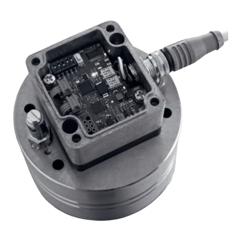
vse VSI 0.04 User manual

1

2
Table of Contents
Importantbasicinformation3
Generalfunctiondescriptionofowmeter4
Generaldescription4
Flowmeterselection4
DeclarationofConformity4
Generalconditionsforinitialstart-up4
Maximumoperatingpressure5
StatementtoEU-Directive97/23/EG,Pressurizeddevices5
Flowmeterrange6
Assemblyoftheowmeter6
Cleaningandushingofpipelinesbeforeinitialstart-up 7
Filteringofliquid7
Flowmeterswithhighdenitionofvolumemeasurement8
Technicalspecicationsofpreamplier 13
Plugassignmentofpreamplier14
Maintenance14
Sendingbackofrepairsandsampledevices15
TechnicalspecicationsVSI002/IPF–VSI4/IPF 15
FlowresponsecurvesVSI002–VSI416
DimensionsVSI002–VSI417
Dimensions,subplatesAP02-418
TechnicalspecicationsVSI10/IPF19
FlowresponsecurvesVSI1019
DimensionsVSI1020
Dimensions,subplateAPG1020
Typekey21
Plugassignment22
Preamplier-blockwiringdiagram22
Connectiondiagram23
EC-DeclarationofConformity23

3
Important basic information
Dear customer, dear user,
These installation and operating instructions should provide you with the information you need to properly install and commission
the ow meter. The installation, commissioning and testing are to be performed by trained and qualied personnel only. These ope-
rating instructions must be read and applied carefully to ensure proper, trouble-free and safe operation of the ow meter. VSE is not
liable for any damage incurred resulting from not complying with the instructions in this operating instruction. It is not permitted in
any case to open the device.
These operating instructions for the ow meters of the series ”VSI High Denition Flow Meter” from VSE must be stored, so that
they can be read by the group of authorized personnel at any time. Chapters may not be taken of these instructions at any time. A
missing operating instructions manual or missing pages must be replaced immediately. VSE can supply you with new instructions or
you can download the operating instructions from the internet (www.vse-ow.com). The operating instructions must be given to each
subsequent user of this product.
Legal information
This document is not managed by an updating service of VSE Volumentechnik GmbH.
Changes to this document may be made without notice.
VSE Volumentechnik GmbH does not provide any implicit guarantees of commercial qualities and suitability for a specic purpose.
If the device has been opened, modied or incorrectly connected to the electrical circuits, the guarantee of VSE Volumentechnik
GmbH for safe operation is void. VSE Volumentechnik GmbH is not liable in any way for personal injuries or damage to goods
resulting from improper installation or improper operating of the ow meter.
Operating manual–no.: E060024 (E) Date 31st May 2006

4
Istheowmeter?
Istheuid?
Istheuidoristherein?
Whichdoesthesolidmatterpossessandcanit?
Doestheuidhaveorother?
Isitnecessarytoinstallapre-switched?
Aretheandfreeofassemblyresiduessuchasswarf,weldchips?
Istheandisitensuredthatcangetintothepipelinesystemfromthetank?
Istheuidoftenchangedandis?
Arethepipelinesandtheentiresystemcompletely?
Whatisbeingused?
Aretheuidandthecleaningagentcompatiblewiththe?
Arethefortheuidundergoingmeasurement?
Flowmetersmadebymeasurethevolume
owofliquidsaccordingtothetoothedwheelprincipleApairofverypre-
ciselyadjustedtoothedwheelsinthehousingconstitutesthemeterAsignal
pick-upsystemregistersmeterrotationfreeofcontactandtoothbytooth
Inowmetersofhighresolution(VSI),eachtoothisoutputasamultipleof
digitalpulses,dependingoninterpolationsetting
Thegapswithintheteethofthemeterwheels,formmeterchambersinthe
areas,inwhichtheyarecompletelyenclosedbythehousingwalls;these
chambersdigitaliseliquidowdependingontheirchambervolume
Theliquidowwithinonemeterrotationofatoothdivisionisdividedbythe
setinterpolationfactorThisgivesthevolumemeasurementperpulse(Vm)
andisdenedincm3/pulseItidentiestheconstructionalsizeofaow
meter(egVSI1/16)
• General description
Pleasefollowallinstructionsinthisoperatingmanual;onlythisguarantees
trouble-freeoperationoftheowmetersVSEisnotliableforanydamage
ensuingfromnotfollowingoftheseinstructions
Openingthedevicesduringthetermofguaranteeisonlyauthorisedafter
consultationandapprovalofVSE
• Flow meter selection
• Declaration of Conformity
Flowmetersofthe“VSI”productlinearetestedfortheirelectromagnetic
compatibilityandinterferencetransmissionintermsofthelawonelectro-
magneticcompatibilityandcorrespondtothelegalprescriptionsenforced
byEMCdirectivesTheymaynotbeoperatedindependentlyandaretobe
connectedviacabletoapowersourceandsupplydigitalelectricsignals
for electronicevaluationA declarationofconformityissubmittedforall
owmeters,whichyoucanrequestifyourequire
Allowmetersaretestedaccordingtothevalid,legallyprescribedelectro-
magneticcompatibilitydirectivesEN55011andEN61000andpossess
theCE-certicationTheEC-declarationofconformityistheCE-labelatta-
chedtoallowmeters
• General conditions for initial start-up
Beforeassemblyandbeforeinitialstart-up,youhavetonotethefollowing
propertiesandaspectsofthecorrespondingcharacteristicsofyoursystem,
sothatatrouble-freeandsafeoperationispossible
• General function description of ow meter

5
Isthelowerthanthemaxpermittedoperatingpressureoftheowmeter?
Isthe(onowmeter)belowthemaxpermittedfallofpressure?
Doesanexcessivelyoccurontheowmeteratmaxow(egwithhigherviscosity)?
Doestheowrangeoftheowmeter(dependingonviscosity)correspondtothe?
Notethatowrangedecreasesthe!
Doesthetemperaturerangeoftheowmetercorrespondtotheofthemedium?
Istheofthepipelinelargeenoughandarethefallsinpressureinthesystemnotexcessive?
Isthe(supplyandreverseow)correctlyconnectedandleak-proof?
Hasthesufcientpowertooperatethesystem?
AblockingowmetercanstopthewholeowIsaprovidedinthesystem?
• Maximum operating pressure
Beforeassembling theow meter,youhave to testthatthemaxopera-
tingpressureofthesystemdoesnotexceedthemaxpermittedoperating
pressureoftheowmeterMeanwhile,observethetoppressuresthatcan
occur,whenoperatingthesystem
Haveyouselectedtheoptimalowmeterandisthisequippedwiththe?
Doestheoftheowmetercorrespondtotheprovidedvoltage?
Isthepowersupplyvoltagesuppliedbythemainsorevaluationdevicesufciently?
Doestheofthepowersupplyvoltagecorrespondtotherequiredpoweroutput?
Hastheelectricconnectionbeeninstalledbasedontheenclosed?
IsthecorrectlyconnectedonbothsidesontheearthconductorPE?
IsthereabetweentheearthconductorPEontheowmeterandtheearthconductorPEontheevaluationdevice?
Doesacorrectingleadhavetobelaidtoeliminatethebetweentheowmeterandtheevaluationdevice?
Istheowmeterconnectedrmlytothe(egviathepipelines)?
IsthemeterconstructedtobetotheearthconductorPE(egconnectionviahoses)?Ifthisisthecase,themeterhastobeconnected
withtheearthconductorPE!
Isthereaofthecableprotectiveshielding(earthconductorPE)viathehousing,ofthe4or5-pinroundplugtothe
housingoftheowmeter?
Isthecablelaidfault-freeandtheinstallationsecuredfrominputof?
Istheoftheconnectioncablermlyscrewedtogetherwiththeplugoftheowmeter?
Arethewiresonthecorrectlyandproperlyconnected?
Doestheentiresystemcorrespondtothedirectivesoftheelectromagneticcompatibilitylaws()?
Havealllocalvalidregulations,,guidelinesandbackgroundconditionsofthe
beenmaintainedandobserved?
SystemsthatcanleadtopersonalinjurythroughmalfunctionorfailurearetobeequippedwiththeThefunctioning
ofthesesafetydevicesistobecheckedatregularintervals
Thefollowingoperatingpressuresarepermitteddependingonowmeter
version:
Flowmeteringreycastironversion pmax=315bar/4500psi
Flowmeterinstainlesssteelversion pmax=450bar/6500psi
Important:
Please consult VSE for all operating pressures > 450 bar / 6500 psi and for special versions.
• Statement to EU-Directive 97/23/EG, Pressurized devices
VSEowmeterarepressurizeddevicesaccordingtoarticle1,paragraph
214ofabovementioneddirectiveThereforetheyaresubjecttotheregu-
lationstothisdirective
Accordingtoarticle3,paragraph14,VSEowmetershavetoconform
withthetechnicalrequirementsoftheguidelineTheuidstobemeasured
arebelonginginmostofallcasestotheclass2,denedinarticle9,para-
graph22VSEowmeterdonotreachthelimitvaluesasdenedinarticle
3,paragraph11
ThetechnicalrequirementsforVSEowmetersthereforearelimitedtothe
parts indicated in article 3, paragraph 3 It means the devices have to
be designed and manufactured in conformity with acknowledged engi-
neering, suchas practiced in one of the member states This is herewith
conrmed
BesidethistheparagraphdeclaresthatthesedevicesmustnothaveaCE-
markingaccordingtoDirective97/23/EGThereforewedonotissuede-
clarationsofCEandourproductsarenotlabelledaccto97/23/EG

6
• Assembly of the ow meter
Theowmetershouldbemountedonaneasilyaccessiblelocation,sothat
dismantlingforcleaningthemeterpresentsnoproblemSinceowmeters
canworkinanyinstallationpositionandowdirection,youcanmountiton
anylocationofyoursystemTakecare,wheninstallingtheowmeterthat
liquidalwaysremainsintheowmeter,evenatsystemstandstillandthatit
canneverrunemptyTheoutowoftheowmetershouldthereforealways
showacertainbackpressure,sincethisclampstheowmeterrmlyinthe
liquidcolumn(themetersupportsitselfthroughthisontheliquidcolumn)
andthepipelinecannotrunemptyIncriticalcasesorwhenthepipeline
isatstandstillorstandbyandcanrunempty,werecommendinstallingan
extranon-returnvalveintheoutowline
Flowmetersofthe“VSI”productlinecanbemounteddirectlyontoablock
orintothepipelineusingfourscrewsAlwaysselectlargecrosssections
forthehydraulicsupplyandreturnowrespectivelyfortheentirepipeline
system(ifpossible)Thislowersthefallinpressureandtheowrateinthe
totalsystem
Important:
Make sure that the specied maximum permitted operating pressure of the ow meter
cannot be exceeded, whatever the operating mode of the system. Note the ow meter
range that is dependent on the viscosity of the uid to be measured.
Important:
Make sure that the ow meter is always completely lled both in inow and outow
and that the outow has a little back pressure. This prevents the meter being damaged by
a sudden and steep increase of ow and at the same time improves measurement accuracy.
Fig. 1: Flow meter installation with non-return valve
VSI002;VSI004;VSI01;VSI02 15Nm
VSI04;VSI1;VSI2 35Nm
VSI4 120Nm
VSI10 250Nm
VSEsuppliessubplatesforallowmetersofthe“VSI”productline;they
havevariouspipethreadsandsideorrearsideconnection(seesubplates
datasheet)Dependingontheprovidedconditions,theinstalledpipeline,
thepipecrosssectionorpipethread,theoperatorcanchoosethesuitable
subplateandincorporatethisintothesystemormachinewithoutadditional
reductions
TheowmeterisscrewedontotheblockorsubplatewithfourDIN912
cheeseheadscrewsThescrewsaretobeevenlypre-tensedcrosswisewith
thefollowingtorques
When changing the fastening screws you must take great care that the
screwsareofpropertyclass109and129
The ow meter is directly mounted onto a subplate or manifold, extra
componentsarenotneededTheblockcontainsthehydraulicsupplyand
outow of the ow meter and the xing bore holes (see ow meter
dimensionsheet)
Please note the special instructions for mounting sizes VSI 4 and VSI 10
(see appendix)
• Flow meter range
Theowmeterrangespeciedintheowmeterdatasheet(Qmin-Qmax)
referstothetestinguid“hydraulicoil“withaviscosityof21mm2/sata
temperatureof20°CForthisowmeterrange,VSEspeciesmeasurement
accuracyofupto03%ofthemeasurementvalueandarepetitionaccu-
racyof005%
Foruidsoflower viscosity (< 21 mm2/s)measurementaccuracy deteri-
orates, while for uids of higher viscosity (> 21 mm2/s) it can improve
Alsonote,however,thattheowmeterrangeisrestrictedincaseofhigher
viscosity(seeowmeterdatasheet)
Non-returnvalve
Flowmeter
Tank

7
• Filtering of liquid
Stronglycontaminateduidsorextraneousmaterialintheuidcanblock,
damageorevendestroytheowmeterAlwaysinstallasufcientlylarge
lterforthesecasesinfrontoftheowmetertopreventdamagetotheow
meterThenecessarylteringdependsonsize,bearingsystemandmodel
ofowmeter
Important:
Please ush out the pipe lines and the tank thoroughly, to prevent contamination
within the ow meter.
Important:
When mounting the ow meter, you must take great care that the seals are not damaged and
correctly placed in the hydraulic connections of the ow meter. Wrongly installed or dama-
ged seals lead to leakage and to a leaky system, which may have dire consequences.
Please make sure that ow meters with EPDM seals do not come into contact with oil and
greases on a mineral oil basis. These uids can decompose the seals.
The yellow plastic plugs in the hydraulic connections of the ow meter protect the meter
against dirt and contamination during storage and shipping. Before mounting the ow meter
you have to remove these plugs so that in- and outow is free and open.
• Cleaning and ushing of pipe lines before initial start-up
Beforeinitialstart-upoftheowmeter,youmustushandcleanthewhole
systemContaminateduidcaneffectthecorrectfunctionoftheowmeter
orseriouslydamagethemeter
Afterpreparingandconnectingupthesystempipes,youmustrstcarefully
ushandcleanthe wholepipeline systemandthetank Todothis,you
havetomountadiversionplateontotheblockorsubplateinsteadofthe
owmeter,sothattheuidcanowthroughthediversionplateandallex-
traneousmaterial(egswarf,metalchips,etc)canbeushedoutwithout
obstructionUseauidascleansingagent,whichiscompatiblewiththe
uidbeingusedlaterandwhichdoesnotcauseundesirablereactionsYou
canconsultthesuppliersandmanufacturersoftheuidorcontactVSEfor
thecorrespondinginformationVSEsuppliesbypassplatesforallVSI-ow
metersizes
Flowmetersaremeasurementpick-upsystemsmadewithhigh-levelprecisi-
onTheyhaveamechanicalmeterconsistingoftwotoothedwheels,which
isadaptedtothehousingwithnarrowslotsEventhetiniestdamagetothe
toothedwheelsandbearingscancauseameasurementerrorSoalways
makesurethatnoextraneousmaterialgetsintothemeterandthattheuid
owingthroughisalwaysfreefromdirtandcontamination
Afterthesystemhasbeencarefullyushedoutandnoextraneousmaterial
isinthepipeline,youcanmounttheowmeterandcommencetheinitial
start-up
VSI002/004/01 10µm
VSI02/04 20µm
VSI1/2/4/10 50µm
For information on lter size for ow meters with plain bearings, in spe-
cial version, or with specially adjusted meter tolerances, please consult
VSE GmbH.
Important:
A blocking ow meter can stop the whole ow. You have to provide a control
valve / bypass for the system.

8
0°
45°
90°
135°
180°
225°
270°
315°
360°
pulse signal from channel 1
pulse signal from channel 2
zero signal pulse (zero pulse)
one measurement value
interpolation factor IPF = 8
Vm*= Vm/ 8
1/2 Vm *
1/4 Vm*
pulse signal from channel 1 without interpolation
pulse signal from channel 2 without interpolation
0°
45°
0°
180°
360°
90°
270°
1 Vm*
1
1
Division of a single pulse into 360°.
All other signal pulses can be regarded in this way.
Evaluation electronics recognise flow direction from the channel offset of 90°.
Each individual pulse flank is offset 90° and has a value of 1/4 Vm*.
22.5°
11.25°
33.75°
1.pulse
1 2 3 45 67 8
Thepreampliersofthestandardversionforowmetersofthe“VS”pro-
ductlineoutputapulsepertoothgapvolumeVz,whichcorrespondstothe
volumemeasurementVm(Vm=Vz
/pulse)Thistakesplaceintwochannels,
sothatyoucanattainamaximumresolutionof1/4Vzfortheevaluationof
allanksAhigherresolutionisnotpossiblewiththesepreampliers
Butsinceashigharesolutionaspossibleisnecessaryforpreciseandexact
owandvolumemeasurements,thevolumemeasurementVmmustberesol-
vedevenmorethanisthecasewithconventionalpreampliersVSEhas
thereforedevelopedthepreamplierwithinterpolation,withwhichaselec-
tableresolutionofupto64anks(16pulses)perperiodcanbeattained
(seetable 3)Thismeansthatyoucan resolve the volume measurement
Vmwiththispreampliertoamaximumof1/64VmFortheevaluation,this
meansthatapartvolumeof1/64Vmfrompulseanktopulseank(for
quadrupleevaluationorankcount)ismeasured,orafullsignalpulseis
countedaspartvolumeof1/16Vm(pulsecount)(seeg3,interpolation
Vm/16)
This individually programmed high resolution enables you to set the vo-
lume measurement Vm optimally for each provided case of application
Furthermore,newapplicationscanbeavailedofwiththehigherresolution
potential
Fig2showstheresolutionofthevolumemeasurementVmwithaninterpola-
tionfactorof8Thisresolveseachvolumemeasurementintoeightindividu-
alpartvolumesApulseonthesignaloutputofchannel1orchannel2thus
hasavalueofVm*=Vm/8=1/8VmperpulseIndoubleevaluation(ank
evaluationofonechannel)thisresultsinavalueof1/2Vm*=Vm/16=
1/16Vmandforquadrupleevaluation(ankevaluationofbothchannels)
theresultisavalueof1/4Vm*=Vm/32=1/32VmperankEvaluation
electronicscanrecogniseowdirectionfromsignalsoffset90°
• Flow meters with high denition of volume measurement
Measuring,controllingandregulatinginthelowerowrange
Measuring,controllingandregulatinginzeroow
Measuring,controllingandregulatinginbothowdirections
Measuring,controlling,dosingandllingofsmallvolumes
Flowmeterswithinterpolationelectronics(VSI)outputtwodigitalsignals
withprogrammablehighresolutionthatarephase-offset90°(seeg3)
Inadditiontothesignalemission,azerosignalemissionisprovided,which
emitsazerosignalateachfullyregisteredvolumemeasurementVm(see
g2)
Fig. 2: Signal emission of the preamplier with interpolation
(interpolation factor 8)

9
Thepreamplierofthe“VSI”productlinehasaprogrammedinterpolation
factor(IPF)withwhichyoucanprogramnew,differentresolutionsHence
you can program a resolution of 4 to 64 angular steps (see g 4) per
volumemeasurementVmThefrequencymultiplication“f*”liesbetween1
and16(seetable3)
Column1:ProgrammableinterpolationfactorIPF(programmedinthefactory)
Column2:PulsespervolumemeasurementVm
Column3:MaximumresolutionofthesignalanksThesignalanksofchannels1and2areevaluated
Column4:VolumemeasurementVm*resultingfromthemaximumresolutionofthesignalanks
Column5:Maximumresolutioninangledegreesatresolutionofsignalanks
Column6:Maximumfrequencyfmax*atmaximumowQmaxandprogrammedinterpolationfactorIPF
Inpractice,themaximumowQmaxoftheowmeterisseldomrun,sothatalowerfrequencycanbecalculatedThemaximumfrequencyisthen
calculatedaccordingtothefollowingformula:
fmax
° Maximumfrequencyoftheowmetersignals
Qmax
° Maximumowattainedinthecaseofapplicationdescribedhere
IPF Programmedinterpolationfactor
Vm Volumemeasurementoftheowmeter
Example:Flowmeter1/10…maxowthesystemcanberunonatamaximum
Q
max
°=40l/min=666667ml/sec;IPF=10;Vm=1ml/pulse;fmax
°=666667Hz=666667kHz
Atmaxowmax
°=40l/min,theowmeter1/10…outputsafrequencyoffmax
°=666667Hz
*
*
*
1 1 4(quadrupling) Vm/4 90° fmaxx1
228Vm/8 45° fmaxx2
3312 Vm/12 30° fmaxx3
4416 Vm/16 225° fmaxx4
5520 Vm/20 18° fmaxx5
8832 Vm/32 11 2 5° fmaxx8
10 10 40 Vm/40 9° fmaxx10
12 12 48 Vm/48 7 5° fmaxx12
16 16 64 Vm/64 5625° fmaxx16
Only the marked lines are illustrated in the diagram of g. 3
°°

10
Fig. 3: Interpolation of the volume measurement Vm
Important:
Test the connected evaluation electronic system as to whether it can process the maximum
frequency fmax of the ow meter. Check the data from the following table for the relevant
ow meter, or calculate the maximum frequency data fmax° with formula 1.
{
Vm /1
{
Vm /2
{
Vm /4
{
Vm /8
{
Vm /16
channel
channel
channel
channel
channel
channel
channel
channel
channel
channel
°0/°063°0 180°
45° 90° 135° 225° 270° 315° 45° 90° 135° 180°
22.5°
0°
22.5°
5.625°
11.25°
16.875°
If the resolution is sixteen-fold, this gives
a recognition of 22.5° (360°/16)
This results in a resolution of 5.625° (22.5°/4)
when evaluating the flanks of channel 1 and 2
The highest resolution permits recognition of
a measurement volume of 1/64 V .
one measurement volume Vm
360° angle degrees
1. pulse
eslup.2eslup.1
1. pulse 2. pulse 3. pulse 4. pulse
1. 2. 3. 4. 5. 6. 7. 8.
1. 2. 3. 4. 5. 6. 7. 8. 9. 10 11 12 13 14 15 16
1. 2.
m
At initial start-up of the system, you have to program the
(seetable4,column4)inyourevaluationelectronicsas
parametervalue(egmultiplier)Theevaluationelectronicsthenmultiply
everypulsetheowmeteroutputsbythevolumemeasurementVm*and
thuscalculatestheowandthevolumeForowmeterswithhighresolu-
tion, the parameter value is dependent on
volumemeasurementVm(seetable4,column2)andontheprogrammed
interpolationfactorIPF(seetable4,column3)
PleaseconsultthisrstofallforthevolumemeasurementVm*andprogram
thisvalueasparameterintoyourevaluationelectronics
Ontable4youcanviewthecorrespondingvolumemeasurementVm*(see
table 4, column 4) with the real, programmed interpolation factor IPF*
(seetable4,column3)TheK-factorincolumn5isameasurementforthe
resolutionperlitre
Youthengetthemaximumfrequencyfmax*(seetable4,column8)ofthe
signalpulsesforthemaximumowQmax(seetable4,column6)withpro-
grammedinterpolationfactorIPF*Thisfrequencyisdependentonthepro-
grammedinterpolationfactorIPFandincreaseswithrisingresolution
Vm
1st
1st
1st
2nd
2nd
2nd
1st
2nd
1st
2nd

11
1002 50000
16667
2001 100000 33333
3000666667 150000 50000
40005 200000 66667
50004 250000 83333
800025 400000 133333
10 0002 500000 166667
12 000166667 600000 200000
16 000125 800000 266667
1004 25000
16667
2002 50000 33333
3001333333 75000 50000
4001 100000 66667
50008 125000 83333
80005 200000 133333
10 0004 250000 166667
12 000333333 300000 200000
16 00025 400000 266667
101 10000
16667
2005 20000 33333
3003333333 30000 50000
40025 40000 66667
5002 50000 83333
800125 80000 133333
10 001 100000 166667
12 000833333 120000 200000
16 000625 160000 266667
102 5000
15000
201 10000 30000
3006666667 15000 45000
4005 20000 60000
5004 25000 75000
80025 40000 120000
10 002 50000 150000
12 001666667 60000 180000
16 00125 80000 240000
104 2500
16667
202 5000 33333
3013333333 7500 50000
401 10000 66667
5008 12500 83333
8005 20000 133333
10 004 25000 166667
12 003333333 30000 200000
16 0025 40000 266667

12
110 1000
13333
205 2000 26667
3033333333 3000 40000
4025 4000 53333
502 5000 66667
80125 8000 106667
10 01 10000 133333
12 008333333 12000 160000
16 00625 16000 213333
120 500
10000
210 1000 20000
3066666667 1500 30000
405 2000 40000
504 2500 50000
8025 4000 80000
10 02 5000 100000
12 016666667 6000 120000
16 0125 8000 160000
140 250
10417
220 500 20833
3133333333 750 31250
410 1000 41667
508 1250 52083
805 2000 83333
10 04 2500 104167
12 033333333 3000 125000
16 025 4000 166667
1333333333 300
26250
2166666667 600 52500
3111111111 900 78750
4083333333 1200 105000
5066666666 1500 131250
8041666666 2400 210000
10 033333333 3000 262500
12 027777777 3600 315000
16 020833333 4800 420000
Vm = physicalvolumemeasurement(size)oftheowmeter(volumepertoothandpertoothgap)
Qmax= maxow(testconditions)
fmax = maxfrequencyatQmax fmax=Qmax
/Vm
IPF* = programmableinterpolationfactor
* = allcharactersmarkedwith*refertoIPF*
Vm* = interpolatedvolumemeasurement Vm*=Vm/IPF*;K-factor*=1/Vm*
fmax* = maxinterpolatedfrequencyatQmax fmax*=Qmax/ Vm*

13
1Column: Flowmeter,versionandsize VSI01…
2Column: physicalvolumemeasurementVm= 01ml/pulse
(correspondstothevolumemeasurementVmatinterpolationfactorIPF*=1)
3Column: Interpolationfactor=hardwareprogrammed IPF*= 10
4Column: VolumemeasurementV
m*= 001ml/pulse
5Column: ;reciprocalvalueofvolumemeasurementVm
* K-factor*=100000pulse/l
6Column: maximumowoftheowmeter Qmax= 10l/min
7Column: maximumfrequencyatinterpolationfactorIPF=1(seecolumn2) fmax= 16667Hz
(correspondstothevolumemeasurementVmatinterpolationfactorIPF=1)
8Column: maximumfrequency*atprogrammedinterpolationfactor(seecolumn3) fmax*= 166667Hz
Thehigh-levelstagesofthepreamplierarefastlinedriversforthreechan-
nelswithacharacteristicwaveimpedanceadjustmentfor75ΩlinesThey
emitthesignalsofchannelA,channelBandthezerochannelZThepush-
pullhigh-levelstagesaredesignedforhighdriverpowerofapprox300mA
on24V;theyarecurrentlimitingandshort-circuit-proofbyswitch-offatex-
cessivetemperatureCapdiodesagainstVbandagainstGNDprotectthe
emittanceagainst“echoes”througherroneouslyadjustedlinesandagainst
destructionthroughESD
Aswitchingcircuitinthehigh-levelstagemonitorsthevoltagesupplyUbas
wellasthetemperatureandincaseoferrorswitchesallhigh-levelstages
to high impedance The error output is designed as open collector and
likewiseshort-circuit-proof;itsendsanerrormessagetotheexternalelec-
tronicsifthereisamalfunction
Datatransferwith24Vsignalsisdoneasarulewithoutcircuitterminati-
on with a wave impedance An erroneously adjusted circuit termination
causesreections,whichcanrunrepeatedlyhitherandthitherifnoadjust-
mentisprovidedonthesendersideIfthereisafastsequenceofpulses,
transmissionisinterferedwithbythesereections
Iftherearelongconnectionlinesbetweenthepreamplierandtheevalu-
ationelectronicsandalsoahighresolution,lineswithawaveimpedance
ofapprox40Ωto150Ωshouldbeusedandacorrespondingtermination
impedanceconnectedtotheevaluationelectronicsAnoptimaladjustment
ofthetransmissionlineandtheterminationwaveimpedancescanpermit
linelengthsofuptoapprox150…200m
Highinterferenceprotectionisachievedbyalargeoutputamplitudeand
bytheintegratedwaveadjustmentWhenthesignalsonthereceiverside
areguidedthroughoptocouplers,youfurthermoregetagalvanicsepara-
tionbetweensenderandreceiversideandpotentialdifferencescanthus
beavoided
Thereectionofreturnsignalsispreventedinthehigh-levelstageofthe
preamplierbyanintegratedwaveimpedanceadjustmentThisadjustment
enhancesinterference-proofperformance
Scansensor: GMRsensorwithdiplexer;orotherscansensors,whichsupplyasineandcosinesignal;
Numberofsensors: Twoscansensorsforgeneratingthesineandcosinesignal;
Adjustment: Offsetadjustmentbymeansoftwopotentiometers;
Resolution: Programmableinarangeof1–64ankspervolumemeasurementVm;
Frequency: Frequencymultiplication:programmableinarangeof1–16timesthefrequencyofthescansensors
Emissionsignals: ChannelA,channelB,zerochannelZ
ChannelAandB: Twosignaloutputsforemittingthedigitalowsensorsignals;betweenchannelAandchannelBthereisachanneloffsetof90°;
Flowdirection: RecognitionofowdirectionfromchanneloffsetofthesignalsfromchannelAtochannelB
ZerosignalZ: Zerosignal,markstheowofonevolumemeasurementVm;
Outputs: 3currentlimitingandshort-circuit-proofhigh-levelstages(channelA,channelB,zerosignalZ);integratedadjustmenttoa75Ω
waveimpedance;drivercurrentapprox300mAat24Vpowersupply;smallsaturationvoltageupto30mAloadcurrent;short
switchingtimes;integratedfree-rundiodesagainstVbandGND;temperatureprotectionswitchingwithhysteresis;outputsareof
highimpedanceincaseoferror;
The24Vlinedriversaredesignedforcontroltechnologywithcableadjustment;
Errormessages: Short-circuit-proofoutputforissuingerrormessagesatexcessivetemperatureorlowvoltage,lowactive
Operatingvoltage: Vb=8…28VDC
Currentconsumption:Inoload=approx40mA;totalcurrentconsumptiondependingonloadingofoutputs;
• Technical specications of preamplier

14
Fig4showstheplugassignmentofthepreamplierAsyoucansee,this
plughasvepins,theouterfourassignedexactlyastheonesinstandard
preampliersInadditiontothepowersupplyandsignaloutputofchannel
1and2,thereisafthpin,whichemitsthezerosignal
Asarule,onlythefourouterpinsareneededtoevaluatetheowmeter
signals;pinassignmentisthereforethesameasinpreviouslydescribedpre-
ampliersForthisreasonyoucanuseanormal4-wiredconnectioncable
fortheconnectionoftheowmeterButpleasemakesurethattheshielding
ofthecableislaidontheplugsideontothemetalhousingoftheplug
TheshieldingoftheconnectioncableisplacedonbothsidesTheearth
conductorPEisconnectedviatheshieldingfromtheevaluationelectronics
tothepreamplierhousingandthemeterThecableshieldingshouldal-
waysbelaidcontinuouslyasfarastheowmeterandnotinterruptedin
crossconnectorsorbranchsocketsLaytheconnectioncableasdirectly
aspossiblefromtheevaluatingdevicetotheowmeter,sinceinterruptions
arealwaysapotentialsourceoferror
TheowmetermustbeconnectedelectricallywiththeearthconductorPE
Thisisnormallysecuredbytheearthedpipelines
• Plug assignment of preamplier
Important:
Only use well-shielded cables for the connection cable, with a wire cross section of
≥ 4 or 5 x 0.25 mm2. Please make sure that the housing of the round plug is metallic, that it
has a connection for the shielding and that the potential of the earth conductor PE is
connected with the cable shielding and the housing of the preamplier.
Important:
Please make sure that no extra inductive elements are connected in the power supply of the
ow meter, such as contactors, relays, valves etc.
These components are potential sources of interference (especially if the inductive elements
are not provided with an adequate protective circuit), generate high interference pulses,
when switched and can interfere with the functioning of the ow meter, although this
complies with the electromagnetic compatibility directives.
Working life is dependent on operating conditions and thus the specic properties of the
devices, limited through wear, corrosion, deposits or age. The operator is responsible for
regular control, maintenance and recalibration. Any indication of a malfunction or damage
prohibits any further use. On request, we can supply you with a borrowed device for the
duration of repair or overhauling. We advice to a yearly control and recalibration.
• Maintenance
pin 1
power supply
U = 10 – 28 V DC
pin 4
digital signal
2. channel
pin 3
power supply
GND (-U = 0 V)
pin 2
digital signal
1. channel
Top view of plug
metal housing connected
with the shielding and the
earth conductor PE
pin 5
digital signal
zero signal
Fig. 4: Flange plug installed in the preamplier housing of the ow meter
b
b

15
0002…2 1667*IPF…166667*IPF 002/IPF 50000*IPF
0004…4 1667*IPF…166667*IPF 004/IPF 25000*IPF
001…10 1667*IPF…166667*IPF 01/IPF 10000*IPF
002…18 1667*IPF…150000*IPF 02/IPF 5000*IPF
003…40 1250*IPF…166667*IPF 04/IPF 2500*IPF
005…80 0833*IPF…133333*IPF 1/IPF 1000*IPF
01…120 0833*IPF…100000*IPF 2/IPF 500*IPF
10…250 4167*IPF…104167*IPF 4/IPF 250*IPF
:upto03%ofmeasurementvalue(withviscosity>20mm2/s)
:±005%underthesameoperatingconditions
:CastironEN-GJS-400-15(EN1563)or
Stainlesssteel14305
:Ballbearingsorsteelplainbearings(medium-dependent)
:FPM(standard),NBR,PTFEorEPDM
:CastironEN-GJS-400-15(EN1563)315bar/4500psi
Stainlesssteel14305 450bar/6500psi
:–40…+120°C(–40°F…248°F)
:–20…+50°C(–4°F…122°F)
:1…100000mm2/s
:any
:any
:max72db(A)
:10to28volts/DC
:3currentlimitingandshort-circuit-proofhigh-levelstages
lowsignal:0=GND;highsignal:1=Ub-1
:90°±30°max
:1/1±15°max
:Aluminium
:IP65
Itisimperativethatyouencloseanexactdescriptionofthecomplaint,ob-
jection or fault, when returning the device so as to ensure a rapid and
economic repairoftheowmetersand othercomponents Furthermore,
youmustincludeasecuritysheet,whichinformsunambiguously,whichuid
wasrunwiththeowmeterandhowdangerousthisuidis
Themaintenanceoflegalregulationsasregardsworksafety,suchaswork-
placeregulations,accidentpreventionregulations,andstipulationsonen-
vironmental protection, waste disposal and the water management law,
obligesindustrial corporations to protect their employees andother per-
sonsandenvironmentagainstharmfuleffects,whenhandlinghazardous
materialsIffurther safety precautionsarestill necessarydespitecareful
emptyingandcleaningoftheowmeter,informationonthisisimperative
andmustbeincludedwiththereturneddespatch
When returning ow meters to VSE Volumentechnik GmbH, pleasenote
thatinspectionandrepairwillonlybeperformedifthe
oftheutiliseduidisenclosedandtheowmeterscompletely
cleanedandushedThisprotectsouremployeesandsimpliesourwork
• Sending back of repairs and sample devices
• Technical specications VSI 0.02 / IPF – VSI 4 / IPF
Adjustable interpolation factors IPF: 1; 2; 3; 4; 5; 8; 10; 12; 16

16
• Flow response curves VSI 0.02 – VSI 4
Flowresistance∆p
FlowQ
Flowresistance∆p
FlowQ
Flowresistance∆p
FlowQ
Flowresistance∆p
FlowQ
Flowresistance∆p
FlowQ
FlowQ
Flowresistance∆p
FlowQ
Flowresistance∆p
FlowQ
Flowresistance∆p
s
Flowresistance∆p
FlowQ
Flowresistance∆p
FlowQ
Flowresistance∆p
FlowQ
Flowresistance∆p
FlowQ
FlowQ
FlowQ
Flowresistance∆p
FlowQ
Flowresistance∆p
FlowQ
Flowresistance∆p

17
• Dimensions VSI 0.02 – VSI 4
100 80 91 M6 120 9114 58 70 40 20 11x2 28 34
100 80 92 M6 11 5 9115 59 70 40 20 11x2 28 34
100 80 94 M6 99117 61 70 40 20 11x2 28 34
100 80 94 M6 95 9117 61 70 40 20 11x2 30 37
115 90 965 M8 11 5 16 120 635 80 38 34 1796x262 40 50
130 100 101 M8 125 16 124 68 84 72 34 1796x262 53 68
130 100 118 M8 15 16 141 85 84 72 34 1796x262 67 84
180 140 145 M12 20 30 168 110 46 95 45 3617x262 147 184
Dimensions in mm
Stainlesssteelversion
Connectiondiagram
Housingwithoutmillededge
Castironversion
Connectiondiagram
O-ring
Castironversion
Plugpositionfor
VSI002toVSI04andVSI4
Earth
Centringborehole
Centringborehole
PlugpositionforVSI1/VSI2
M12x1
M12x1

18
• Dimensions, subplates AP. 02 - 4
G1/4“
G3/8“
G1/2“
35
20
80 90 40 70
26
100 M6/12 18
23 30
28 38
G1/2“ 35 28 90 100 38 80 46 115 M8/15 27
G3/4“ 40 33 52
G1/2“ 35 28
100 110 72 84
46
130 M8/15 36G3/4“ 40 33 52
G1“ 55 41 55
G11/4“ 70 51 120 130 100
110 60
M8/15 7 4
*G11/2“ 70 56 120 72
G11/2“ 80 140 110 180 120
only for AP . 4 U...
Flowmeter
Subplate
Flowmeter
Subplate

19
VSI10 15…525 750*IPF…262567*IPF 3333/IPF 300*IPF
:upto05%ofmeasurementvalue(withviscosity>20mm2/s)
:±005%underthesameoperatingconditions
:CastironEN-GJS-400-15(EN1563)
:Ballbearingsorsteelplainbearings(medium-dependent)
:70kgwithoutsubplate
:FPM(standard),NBR,PTFEorEPDM
:420bar/6000psi
:–40…+120°C(–40°F…248°F)
:–20…+50°C(–4°F…122°F)
:5…100000mm2/s
:any
:any
:db(A)
:10to28volts/DC
:0…2625Hz
:3currentlimitingandshort-circuit-proofhigh-levelstages
lowsignal:0=GND;highsignal:1=Ub-1
:90°±30°max
:1/1±15°max
:Aluminium
:IP65
• Technical specications VSI 10 / IPF
Adjustable interpolation factors IPF: 1; 2; 3; 4; 5; 8; 10; 12; 16
• Flow response curves VSI 10
FlowQ
Flowresistance∆p

20
• Dimensions VSI 10
• Dimensions, subplate APG 10.
Dimensions in mm
Dimensions in mm
Weight70kg
ConnectionsurfaceVSI10
View X
Weight21kg
Weight30kg
ConnectionsurfaceVSI10
View X
View X
Liftingeyebolt
Barhandle
Liftingeyebolt
O-ring
Connectiondiagram
Earth
This manual suits for next models
9
Table of contents
Other vse Measuring Instrument manuals